|
|

Table Of Contents
7.1.2 Configuration of Static Multicast Forwarding Information
7.2.1 Spanning Tree Protocol (STP) Configuration
7.2.2 Rapid Spanning Tree Protocol (RSTP) Configuration
7.3.1 Virtual Local Area Networks (VLAN)
7.4.1 Configuration Of A New VLAN Per Port
7.4.2 Configuration Of A New VLAN Per Protocol And Per Port
7.4.3 Configuration of an Ethernet User Defined Protocol
7.4.4 Configuration of VLAN Port Members
7.4.6 Provider VLAN (IEEE 802.1Q, Q in Q)
7.5.1 Configure an IP Interface
7.5.2 Configure a Static Route
7.6.1 Open Shortest Path First
Layer 2 Configuration
The purpose of this chapter is guide you through management of the bridging service (L2 forwarding) on the network element.
This includes:
•
Presentation and modification of the bridge.
•
•
•
•
•
Note
7.1 Bridge
This chapter describes the configuration operations supported by the Bridge M.O. It is organized in two sections:
•
•
Troubleshooting and FAQ, see Chapter 9, "Troubleshooting and FAQ." This chapter contains a few tips, and gives answers to a number of Frequently Asked Questions.
7.1.1 Examples
7.1.1.1 Configuration of Static Unicast Forwarding Information
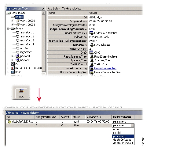
Configure an entry in the MAC unicast forwarding table, Figure 7-1.
Step 1
Step 2
Figure 7-1 Configuration of Static Unicast Forwarding Information
.
Step 3
Step 4
•
Set the bridge port number of the port through which the MAC address can be reached.
•
Set the MAC address. The MAC address must be a unicast address.
•
Set the VLAN ID for which this entry applies.
•
Set permanent if the entry should not be removed dynamically from the table (such an entry will stay over a reset of the bridge). Set deleteOnReset if the entry should be removed dynamically from the table after the next reset of the bridge. Set deleteOnTimeout if the entry should be dynamically aged out by the bridge.
Step 5
7.1.2 Configuration of Static Multicast Forwarding Information
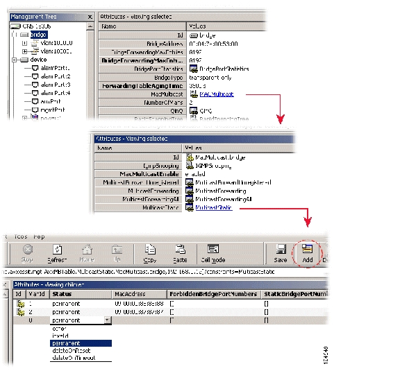
Please see Question 5, page 9-2 before you start Configure an entry in the MAC multicast forwarding table, Figure 7-2.
Step 1
Step 2
Figure 7-2 Configuration of Static Multicast Forwarding Information
.
Step 3
Step 4
•
Set the VLAN ID for which this entry applies.
•
Set the MAC address. The MAC address must be a multicast address.
•
Set the set of ports through which the multicast/broadcast frame must be forwarded regardless of any dynamic information. The set of ports is entered as an octet string where each bit represents one port, for further information see also Chapter 9, "Troubleshooting and FAQ."
•
Set the set of ports through which the frames must not be forwarded regardless of any dynamic information. The set of ports is entered as an octet string where each bit represents one port, for further information see also Chapter 9, "Troubleshooting and FAQ."
•
Set permanent if the entry should not be removed dynamically from the table (such an entry will stay over a reset of the bridge). Set deleteOnReset if the entry should be removed dynamically from the table after the next reset of the bridge. Set deleteOnTimeout if the entry should be dynamically aged out by the bridge.
Step 5
Note
7.1.3 IGMP Snooping
When a host wants to receive multicast traffic, it must inform the routers on its LAN. The IGMP is the protocol used to communicate group membership information between hosts and routers on a LAN. Based on the information received through IGMP, a router forwards multicast traffic only via interfaces known to lead to interested receivers (hosts).
On the contrary, bridges flood multicast traffic out all ports per default, and therefore waste valuable network resources. IGMP snooping on a bridge can eliminate this inefficiency. IGMP snooping looks at IGMP messages to determine which hosts are actually interested in receiving multicast traffic. Based on this information, the bridge will forward multicast traffic only to ports where multicast receivers are attached.
7.1.3.1 Enabling IGMP Snooping
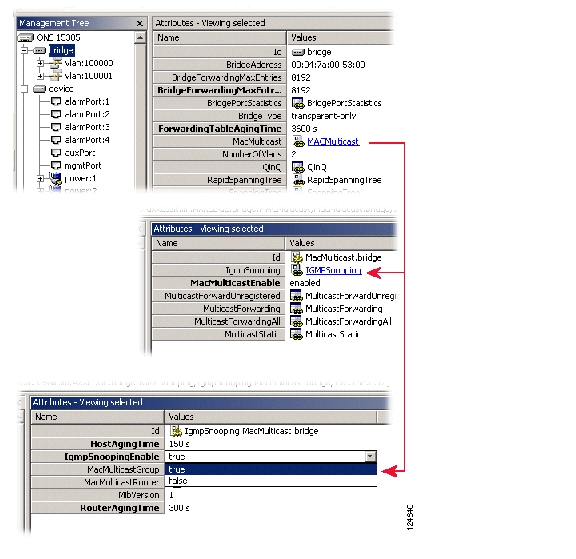
Enable IGMP snooping on the network element, Figure 7-3.
Step 1
Step 2
Step 3
Step 4
Step 5
Step 6
Figure 7-3 Enabling IGMP Snooping
7.2 Miscellaneous
This section describes STP, RSTP, MAC Multicast and Traffic control.
7.2.1 Spanning Tree Protocol (STP) Configuration
The STP allows layer 2 devices to discover a subset of the topology that is loop-free, but still with a path between every pairs of LANs.
STP is compatible with the RSTP. See Rapid Spanning Tree Protocol (RSTP) Configuration)
The network element can run either one single STP algorithm for the whole device (per Device type), or one STP algorithm per VLAN (per VLAN type). The type of STP algorithm can be selected by setting the ONS 15305> Bridge > SpanningTree > stpTypeAfterReset attribute. The network element must be restarted for the new STP type to become effective.
7.2.1.1 Configuring the STP Algorithm per Device
Configure the STP algorithm per device.
Step 1
Step 2
Step 3
Step 4
Step 5
Step 6
Step 7
Step 8
Step 9
Step 10
Step 11
7.2.2 Rapid Spanning Tree Protocol (RSTP) Configuration
The original STP uses rather long time to recalculate paths after a topology change. Because of the growing use of larger switched networks, this has become a potential reason for performance degradation in certain cases. Rapid STP is one of several attempts to improve on this issue. The ONS 15302 and ONS 15305 support only a partial RSTP implementation which offers the same type of service as e.g. PortFast on Cisco equipment, as it does not support the actual creation of a spanning tree among the bridges. It will however get the ports facing customers to Forwarding mode without having to wait for 2 x Forwarding delay as is the case with the original STP. The regular STP must be running to prevent loops in network. RSTP is to be used only on ports facing end-user equipment. If the ONS 15302 or ONS 15305 detects normal STP BPDUs on an interface configured for RSTP it will switch back to normal STP for that interface.
Due to the partial implementation, only the Port-Table and its commands are operational at the first release of ONS 15302 and ONS 15305.
7.2.2.1 Configure RSTP on a port.
Step 1
Step 2
Step 3
Note
Step 4
Step 5
7.2.3 MAC Multicast
Multicast is a method of sending one packet to multiple destinations. Multicasting is used for applications such as video conferencing, and for distribution of certain information like some routing protocols. A standard IEEE 802.1D bridge will forward multicast frames on all ports that are members of the same VLAN as the port receiving such frames. This might not be desirable if the there is a lot of multicast traffic being transported through a multi-port bridge where the recipients are connected on only one (or a few) of the bridge ports. To alleviate unnecessary bandwidth consumption, the ONS 15302 and ONS 15305 support specific tables to control the forwarding of Multicast traffic if desired. Both devices also supports IGMP (Internet Group Management Protocol) snooping which is used to update the multicast tables based on the IGMP messaging between end nodes and IP multicast routers.
Note that multicast traffic will be forwarded as usual if this feature is not enabled, and that the use of these tables are only necessary for performance tuning.
7.2.3.1 Enabling MAC Multicast Control Tables
The internal resources of the ONS 15302 and ONS 15305 used for the multicast tables are shared with the VLAN tables. The total of VLAN entries and multicast groups registered are 4000, and both types of entries occupy the same amount of resources. Hence, to enable the Multicast feature, ensure that the maximum amount of VLANs is less than 4000 according to how many multicast groups anticipated. For most applications 4000 VLAN are well above what will be used, and in these cases one can safely reserve a good chunk of entries for multicast traffic.
Configuring MAC Multicast
Multicast menu has the following menu options:
•
•
•
•
•
•
The parameter MacMulticastEnable is for enabling/disabling of the MAC Multicast control tables.
7.2.3.2 MulticastForwarding
The Forwarding-Table contains multicast filtering information configured into the bridge, or information learned through IGMP Snooping. The Forwarding-Table information specifies the allowed egress ports for a given multicast group address on a specific VLAN, and indicates for which ports (if any) this information has been learnt from IGMP snooping.
VLAN-TAG-ID: Identifies the VLAN to which the filtering information applies.
MULTICAST-ADDRESS: Identifies the destination group MAC address to which the filtering information applies.
EGRESS-PORTS: Indicates the configured egress ports for the specified multicast group address. This does not include ports listed in the Forward All Ports list for this address.
LEARNT: Indicates a subset of ports from the Egress Ports list which were identified by IGMP Snooping and added to the multicast filtering database.
7.2.3.2.1 MulticastForwardingAll
The Forward-All-Table allows ports in a VLAN to forward all multicast packets.
VLAN-TAG_ID: Identifies the VLAN to which the filtering information applies.
EGRESS-PORTS: Specifies which ports on a VLAN can participate in a Forward Unregistered group. The default setting is all ports.
FORBIDDEN-PORTS: Specifies which ports on a VLAN are restricted from participating in a Forward All group.
STATIC PORTS: Indicates if the egress ports are static or dynamic configured.
7.2.3.2.2 MulticastForwardUnregistered
The Multicast-Forward-Unregistered-Table defines the behavior of ports regarding forwarding of packets that is not covered by any of the other tables.
VLAN-TAG_ID: Identifies the VLAN to which the filtering information applies.
EGRESS-PORTS: Specifies which ports on a VLAN can participate in a Forward Unregistered group. The default setting is all ports.
FORBIDDEN-PORTS: Specifies which ports on a VLAN are restricted from participating in a Forward Unregistered group.
STATIC PORTS: Indicates if the egress ports are static or dynamic configured.
7.2.3.2.3 MulticastStatic
The Static-Table contains manually configured filtering information for specific multicast group addresses. This includes information about allowed and forbidden egress ports, and is also reflected in the Forwarding-Table.
VLAN-TAG_ID: Identifies the VLAN to which the filtering information applies.
MULTICAST-ADDRESS: Identifies the destination group MAC address of a frame to which the filtering information applies.
STATIC-EGRESS-PORTS: Indicates a set of ports to which packets received from, and destined to, are always forwarded. This is regardless of the IGMP Snooping setting.
FORBIDDEN-PORTS: Indicates the set of ports to which packets received from and destined to a specific port must not be forwarded. This is regardless of the IGMP Snooping setting.
STATUS:
The possible values are:Permanent—The table entry is currently in use. When the bridging status is reset this table entry remains in use.
Delete on Reset—This table entry is currently in use. However, when the bridging status is reset the entry is deleted
Delete on Timeout—This table entry is currently in use. However when the bridge times out the entry is deleted.
7.2.4 Traffic Control
The Traffic Control menu has the following menu options:
•
•
•
7.2.4.1 PortPriority
BridgePortNumber: a port number identifying one of the on the device. For each row, the information in the row applies to the port identified in this column.
DefaultPriority: this is the priority value assigned to frames arriving at this port, when implicit priority determination is used. Any frames arriving at this port, not carrying a priority value in a tag, will get the DefaultPriority value as priority. The value is an IEEE 802.1p priority level. Range is 0 - 7, inclusive.
NumberOfTrafficClasses: gives the number of classes of service - that is, the number of output queues, for the port. All ports on the device will always use 4 queues.
7.2.4.2 PriorityGroup
BridgePortNumber: a port number identifying one of the on the device. For each row, the information in the row applies to the port identified in this column.
PriorityGroup: indicates which ports are located on the same module, and are thus using the same priority configuration. The ONS 15305 has a theoretical maximum of 65 ports, which are all listed in this table whether or not they are present. PriorityGroup 32 indicates that the port is not present (i.e. the corresponding slot holds a STM-n module which has no Ethernet interfaces).
7.2.4.3 TrafficClass
Classification of Ethernet frames are done according to the information in the TrafficClass table. The device use four queues for differentiating traffic, and as 802.1p defines eight different priorities, the priorities must be mapped into those four queues. The default mapping scheme is as recommended by IEEE, but this is configurable by the operator.
Recommended mapping when using four queues.
BridgePortNumber: a port number identifying one of the on the device. For each row, the information in the row applies to the port identified in this column.
Priority: priority value according to 802.1p. Legal values 0-7.
TrafficClass: indicates which service queue the selected priority value is to be mapped to. Legal values 0-4 (4 is highest priority).
7.3 Manage VLAN
The purpose of this section is to guide you through management of a VLAN on the network element.
A network element can be configured to run either VLAN per port or VLAN per port and per protocol.
The section also involves management of the complete life cycle of a VLAN, including:
•
•
•
7.3.1 Virtual Local Area Networks (VLAN)
A LAN consists of a number of computers that share a common communication line within a small geographical area. A Virtual LAN is a LAN where the grouping of computers are based on logical connections, for example by type of users, by department etc. It is easier than for a physical LAN to add and delete computers to/from a VLAN and to manage load balancing. The management system relates the virtual picture and the physical picture of the network.
The network element supports two types of VLAN
•
•
Both types of VLANs cannot be run simultaneously on the network element, that means either all VLANs per port or all per port and per protocol. The protocol can either be one from a set of predefined protocols or from Ethernet protocols defined by you. Different Ethernet protocol types can be IP, IPX, Appletalk, etc.
The number of Ethernet-ports in ONS 15305 which can be assigned to a VLAN, is limited to 64. The maximum number of Ethernet-ports per slot is 16.Alsosee Troubleshooting and FAQ, Question 7, page 9-3.
There are three steps involved in the definition of VLAN on the network element.
•
•
•
It is assumed you have the appropriate rights to perform management operations.
7.3.1.1 Tagged/untagged LAN ports
In order to transport traffic from multiple VLANs over the same LAN port (from one bridge to another) the Ethernet frames must be tagged according to what VLAN they belong to, so that the connected bridge knows what frames are to be forwarded into which VLAN (This is according to the IEEE spec 802.1Q). This is done by inserting four bytes into the Ethernet frame header, with information about the VLAN ID (VID) the frame is associated with. The VID of a specific VLAN is defined at the time the VLAN is created. This tagging can be enabled for each port in a VLAN. This is, however, only used for communication between bridges (and in some cases VLAN aware servers), and not on ports facing regular end user network equipment. A LAN port operating in untagged mode will discard tagged frames on ingress. LAN ports operating in tagged mode will only accept frames tagged in accordance with the VID of the VLAN(s) of which the port is a member.
Example:
If a port is member of two VLANs with the VIDs of 10 and 20, and the port receives frames tagged according to VID 10, 20 and 30, only the frames with VID 10 and 20 will be accepted and forwarded. The frames with VID 30 will be discarded.
It is absolutely possible to have a VLAN where some of the member ports are tagged while others are not. As long as there is traffic from only one VLAN passing through a port, there is no need to enable tagging.
7.4 VLAN Provisioning
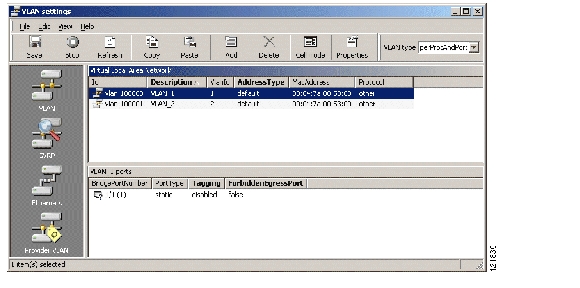
Cisco Edge Craft has a custom GUI for VLAN provisioning, Figure 7-4. The VLAN GUI makes VLAN related configuration easier for the user by grouping together a number of managed objects and attributes under a unique GUI.
Figure 7-4 VLAN GUI - Overview
.
The following examples show how a VLAN per port, and a VLAN per port and protocol can be created and provisioned by using the custom GUI. The VLAN custom GUI can be opened either by clicking on VLAN Setting under the Bridge menu on the Cisco Edge Craft desktop, or by right-clicking on Bridge M.O. in the topology browser, and then selecting VLAN Setting.
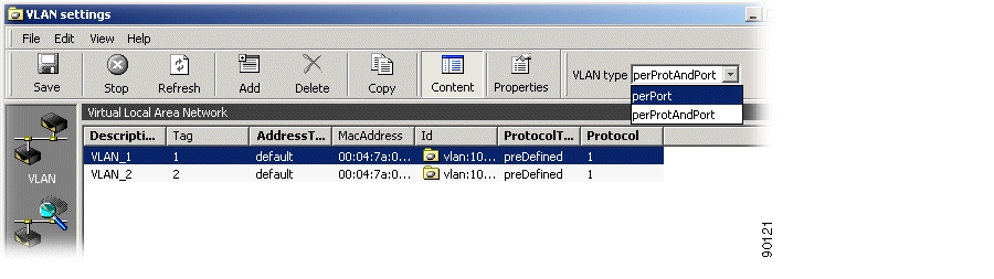
7.4.1 Configuration Of A New VLAN Per Port
Create a new VLAN per port.
Step 1
Figure 7-5 VLAN Settings
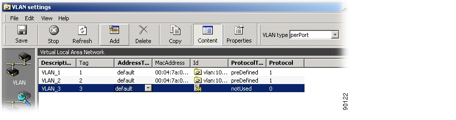
Step 2
Figure 7-6 Add a VLAN
.
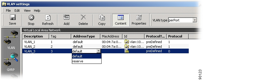
Step 3
Figure 7-7 Set VLAN Attributes
.
Step 4
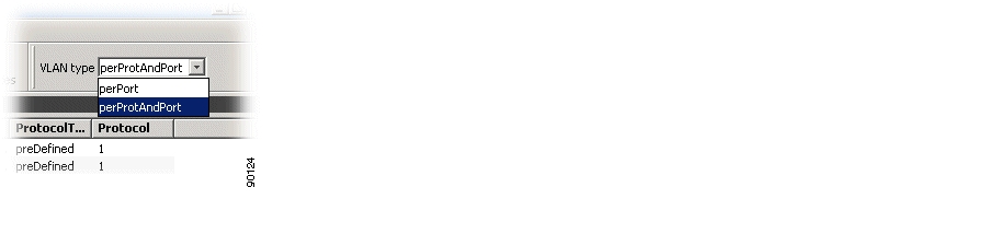
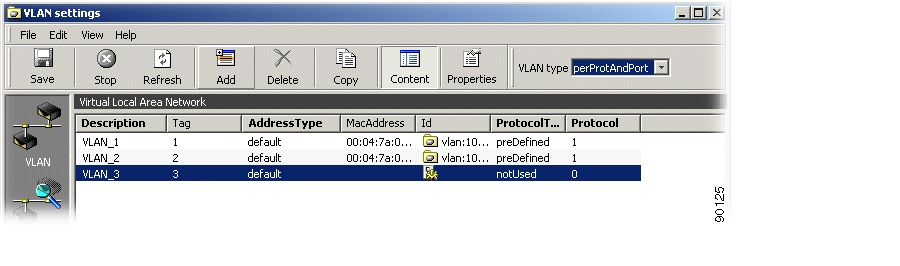
7.4.2 Configuration Of A New VLAN Per Protocol And Per Port
Create a new VLAN per protocol and per port.
Step 1
Step 2
Figure 7-8 Add a VLAN
Step 3
Figure 7-9 Configure a VLAN
.
Note
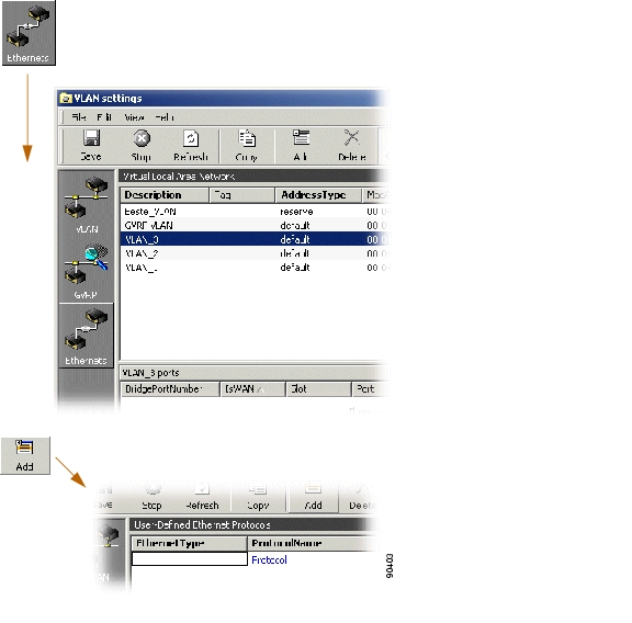
7.4.3 Configuration of an Ethernet User Defined Protocol
How to configure an ethernet user defined protocol:
7.4.3.1 Use The Ethernet User Defined Protocol
The ethernetDefinedProtocol attribute allows you to define a non-predefined protocol based on the etherType field of Ethernet frames. This user-defined protocol is further used to create protocol-based VLANs, Figure 7-10.
Step 1
Step 2
Figure 7-10 Configuration of an Ethernet User Defined Protocol
.
Step 3
Step 4
Step 5
Note
Assuming that a user wants to define a VLAN based on the address resolution protocol (ARP), the ethernetType must be set to 0806 (in hex), and the protocolName attribute could be, for example set to ARP to identify the protocol.
The Ethernet user defined protocol is relevant only when the network element runs VLAN per protocol and port.
Maximum one Ethernet user defined protocol can be currently defined on the network element.
To use the Ethernet user defined protocol as a VLAN protocol for a particular VLAN, set the protocolType attribute under Bridge > VLAN to ethUserDefined. The protocol attribute under Bridge > VLAN, which is used to identify a specific protocol, must then always be set to 1, since there is maximum one Ethernet user defined protocol.7.4.3.2 Use One Of The Pre-defined Protocols
Step 1
Step 2
.
Step 3
Step 4
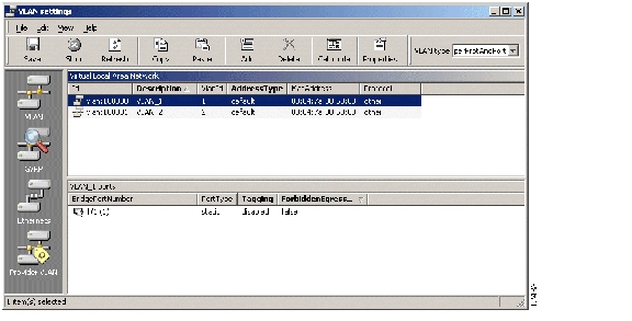
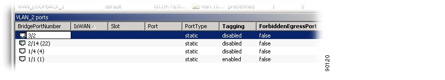
7.4.4 Configuration of VLAN Port Members
Add port members to an existing VLAN
Step 1
Figure 7-11 Configuration of VLAN Port members
Step 2
Step 3
Step 4
Note
Figure 7-12 Edit the Bridge Port Number
Step 5
Step 6
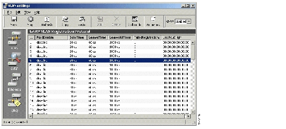
7.4.5 GVRP
GARP VLAN registration protocol (GVRP).
Step 1
Figure 7-13 GVRP Attributes
The following attributes are modifiable:
•
Set to enabled or disabled.
•
Set value in centiseconds.
•
Set value in centiseconds.
•
Set value in centiseconds.
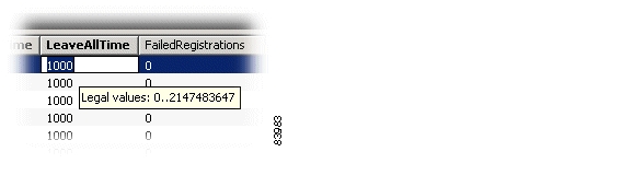
7.4.5.1 Legal time values
Click in desired attribute cell and focus the mouse pointer over the cell. A tooltip will display legal value range for the selected attribute, Figure 7-14.
Figure 7-14 Select Legal Time Values
7.4.6 Provider VLAN (IEEE 802.1Q, Q in Q)
7.4.6.1 Overview
The 802.1Q Tunneling is part of the Layer 2 switching capabilities of the Cisco ONS 15300 SDH product line. The desired functionality enables the operator to tunnel separate customer traffic, containing 802.1Q tagged (VLAN tagged) Ethernet frames, through a second layer of VLANs. This allows the operator to be oblivious to the customers VLAN schemes, and focus on managing only one VLAN per customer through the network. At the same time, the different customers on a shared device can use whatever VLAN IDs they choose without the risk of interfering with each others VLAN schemes.
7.4.6.2 Definitions
•
By tunnel port we mean a LAN port that is configured to offer 802.1Q-tunneling support. A tunnel port is always connected to the end customer, and the input traffic to a tunnel port is always 802.1Q tagged traffic.
The different customer VLANs existing in the traffic to a tunnel port shall be preserved when the traffic is carried across the network.
•
By trunk port we mean a LAN port that is configured to operate as an interswitch link/port, able of carrying double-tagged traffic. A trunk port is always connected to another trunk port on a different switch. Switching shall be performed between trunk ports and tunnels ports and between different trunk ports.
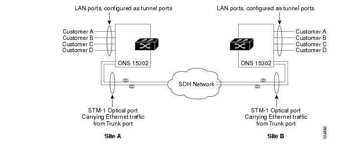
7.4.6.3 Applications - examples
Application 1Application 1 is two ONS 15302 connected back to back over an SDH network as shown in Figure 7-15, carrying Ethernet traffic from different customers using double tagging (802.1Q tunnelling).
Figure 7-15
Application Example 1
In this application both the tunnel ports and the trunk port is on the same switch.
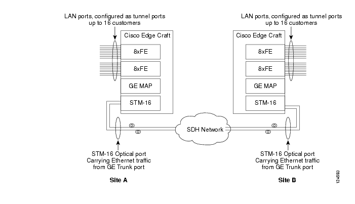
Application 2Application two is two ONS 15305 connected back to back over an SDH network as shown in Figure 7-16, carrying Ethernet traffic from different customers using double tagging (802.1Q tunnelling). This application is equal to application 1 except that the number of tunnel ports is increased and the trunk port is a GE port, which requires an STM-4 or STM-16 optical interface.
Figure 7-16
Application Example 2
The customer tunnel ports are FE ports, while the trunk port mapped into the SDH traffic is a GE port. In this application the tunnel ports and the trunk ports resides on different switches.
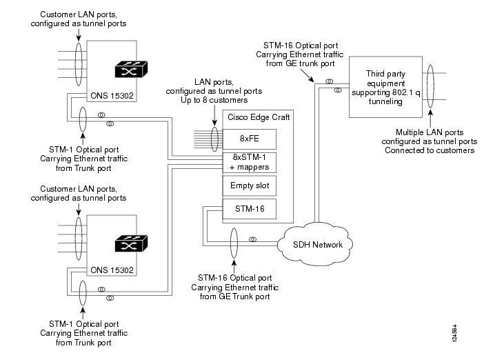
Application 3In application 3, shown in Figure 7-17 below, the ONS 15305 has the same trunk port towards the network as in application 2, but 8 of the tunnel ports towards the customers are removed and replaced of 8 STM-1 ports connected to ONS 15302 devices (for simplicity only two ports and two ONS 15302 devices are shown). Each of the 8 STM-1 ports is connected to a switch via a mapper circuit. The LAN ports are configured as trunk ports, making them able to talk to the trunk ports on the ONS 15302s. This application also includes switching between trunk ports.
Figure 7-17
Application Example 3
7.4.7 Provider VLAN
7.4.7.1 Setting up Provider VLAN - ONS 15305
Depending on network element and module version, the Provider VLAN features is implemented on two different levels:
•
•
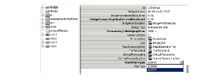
Step 1
Figure 7-18
VLanEtherType
Step 2
Set 0xFFFF for configuration in Switch. This setting completes the QinQ configuration for old modules
Set 0x8100 for configuration through Policer (new modules only).Continue configuration as described in Setting up Provider VLAN - ONS 15305.Step 3
Note
7.4.7.2 Setting up Provider VLAN - ONS 15305 with FE/GE+SMAP modules
Note
Step 1
Figure 7-19
VLanEtherType
Step 2
Step 3
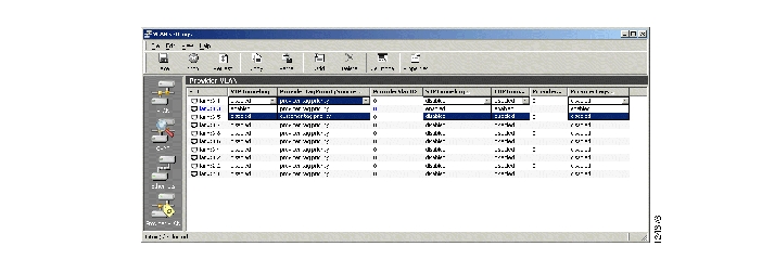
Figure 7-20
Provider VLAN
7.4.7.3 ProtocolTunneling
Enabling the ProtocolTunneling attribute makes the port transparent to other Layer 2 protocols, such as RSTP.
As an example, If a Service Provider VLAN manages his own Spanning Tree, the Network Owner may need to exempt the port used by the Service Provider from the Network Owners own spanning trees to prohibit the two spanning tree protocols from interfering with each other.
7.4.7.4 ProviderTagPrioritySource
Ethernet packages in a VLAN is allocated a priority that controls the packets flow through the network switches. When entering Service Provider VLAN traffic into a Network Owner VLAN, this attribute controls if the Network Owner VLAN shall inherit the Service Provider VLAN priority settings, or assigns his own priority settings.
taginframe forces the Network Owner VLAN to inherit the Service Provider priority.
qtagregister assigns a Network Owner custom priority to his VLAN traffic. The priority is read from a local data register.
7.4.7.5 VLANProviderID
This attribute identifies the Service Provider VLAN that uses the highlighted LAN/WAN port.
7.4.7.6 ProviderTagPriority
This attribute sets the custom priority value (0.7) that is used when the ProviderTagPrioritySource is set to "qtagregister".
7.4.7.7 ProviderTags
This attribute enables or disables QinQ (Provider VLAN) support on the selected port.
Step 4
Step 5
7.4.7.8 Setting up Provider VLAN - ONS 15302
Note
Step 1
Step 2
The switch will now operate with a proprietary VLAN Ethertype; 0xFFFF.
Using a VLAN with one LAN port and one WAN port, where the LAN port is untagged and the WAn Port is tagged, the switch will enter an additional VLAN tag. This tag is identified by the type 0xFFFF and has priority as set in Bridge>TrafficControl>PortPriority (default priority for this port). The tag has VLAN ID as indicated in the VLAN Table.
The Provider Tag configuration allows the Mapper in the FPGA to switch the proprietary 0xFFFF to 0x8100, enabling these frames to switched by other 3rd party switches.
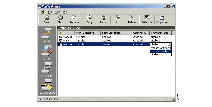
Step 1
Step 2
disabled,
transparent priority: use the default port priority
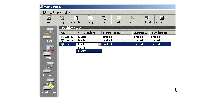
or extract priority: inherit priority from the customer traffic.Figure 7-21 Provider Tags Setting
Step 3
Step 4
7.4.7.9 Enabling Protocol Tunneling
ProtocolTunneling is default set to NA (due to STP enabled).
Figure 7-22
Protocol Tunneling
To enable ProtocolTunneling please follow these steps:
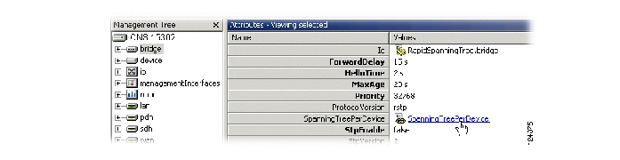
Figure 7-23
SpanningTreePerDevice
Step 1
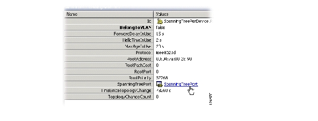
Step 2
Figure 7-24 SpanningTreePort
.
Step 3
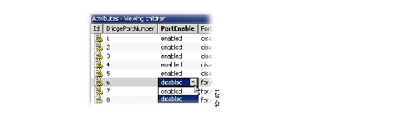
Figure 7-25
PortEnable
Step 4
Step 5
Figure 7-26
Protocol Tunneling
Step 6
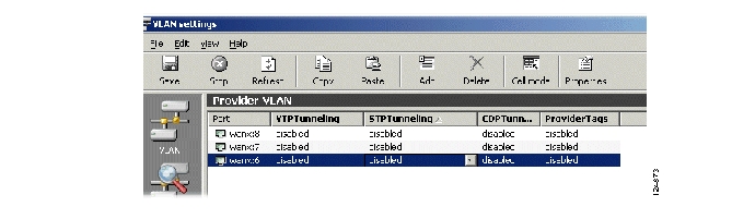
disabled, transparent priority or extract priorityFigure 7-27 ProviderTags
<$chapnum>.0.1 QinQThe following section focus on QinQ settings for ONS 15305 Release 1.1
and ONS 15302 Release 1.0.This implementation is using the value 0xFFFF as Ethertype for the Provider VLAN. Hence, Provider VLAN tagged traffic will not be recognized as VLAN tagged traffic according to 802.1Q (as the later implementation does) if sent through third party VLAN aware switches.
For these network element releases, the QinQ implementation is different than described in "Provider VLAN (IEEE 802.1Q, Q in Q)" on page -19.
For ONS 15305 the following QinQ settings are available (depending on selected module type); available ports, disable and enable.
For ONS 15302: disable or enable.
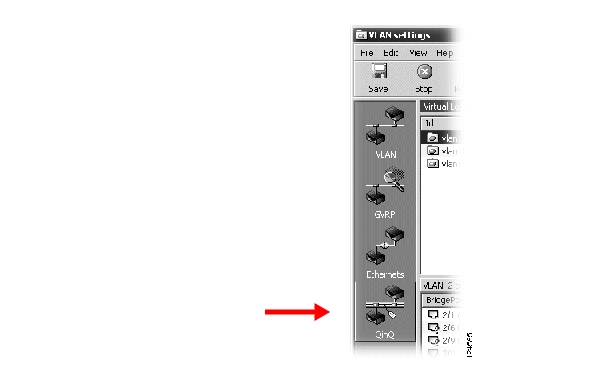
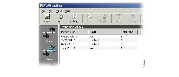
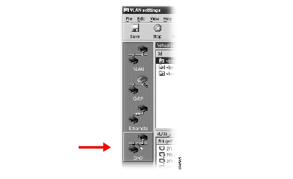
7.4.7.10 Setting up Q in Q - ONS 15305
Step 1
Available modules types with Q in Q available, are displayed:
Step 2
Step 3
Step 4
7.4.7.11 Setting up Q in Q - ONS 15302
Step 1
Step 2
Step 3
Repeat for other network elements that are part of the desired Q in Q application. (Select File>Reconnect to access the other NE's)
7.5 Examples
These examples describe how to configure an IP Interface, Static route, Default route and RIP filter.
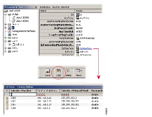
7.5.1 Configure an IP Interface
An IP interface can be created only for a physical port, a management interface, or a VLAN (port based VLAN or IP-based VLAN only).
Configure an IP interface with an IP address, Figure 7-28.
Step 1
Step 2
Step 3
Figure 7-28 Configuration of an IP Interface
.
Step 4
•
set the IP address according to your addressing plan.
•
set the network mask according to your addressing plan.
•
the interface number. An IP interface can be defined for a LAN port, a WAN port, the management port, a DCC running IP or a VLAN. The interface number corresponding to these objects is specified by the ifIndex attribute present under their respective M.O.
Step 5
Note
IP addresses and network masks associated with the management interfaces, that means the management port, and the DCC can also be edited via the management interfaces M.O.7.5.2 Configure a Static Route
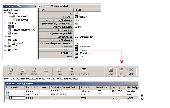
An IP static route is a route defined by the user through the management system. Such a route does not age out, and will stay in the network element routing table as long as it is not explicitly deleted by the user. As any other route, a static route is active, and therefore included in the forwarding table provided that the interface associated with the route is up.
Note
7.5.2.1 Create a Static Route
Step 1
Step 2
Step 3
Figure 7-29 Create a Static Route
.
Step 4
Step 5
Step 6
Step 7
Note
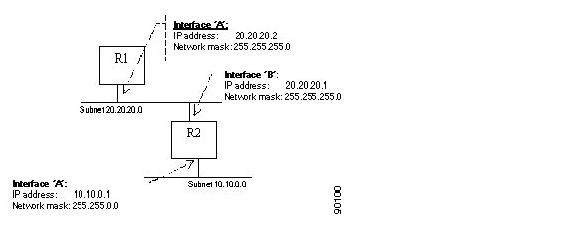
The IP address of the next router en route specified by the next-hop attribute must be directly reachable via the interface specified by the interfaceNumber attribute, that means the next-hop IP address must belong to the (one of the) subnet(s) defined for the interface identified by the interfaceNumber attribute.ExampleTo define a static route to the subnet 10.10.0.0 in router R1, Figure 7-30.
Figure 7-30 Figure - Static Route in Router R1
Step 1
Step 2
Step 3
Step 4
Step 5
Step 6
7.5.2.2 Configure a Default Route
A default route is a particular static route which is used to by the network element to send all the traffic for which no other routing information exists. If no default route has been defined, and no specific routing information exists for an IP datagrams requesting forwarding, the datagram is discarded.
The default route is created by setting both the destinationIpAddress and the destinationNetworkMask attributes to 0.0.0.0. The router identified by the next-hop attribute is then referred to as default router, also know as default gateway.
Note
Example
To create a default route on router R1 using router R2 as default gateway, Figure 7-30.
Step 1
Step 2
Step 3
Step 4
Step 5
Step 6
7.5.3 Configure a RIP Filter
An IP RIP filter allows the user to control the propagation of RIP routing information, and eventually to modify the RIP routing by filtering out information about specific routes. In addition, IP RIP filters help reducing the size of the RIP table allowing for a faster table look-up, and releasing memory for other processes.
7.5.3.1 Create an IP RIP Global Filter:
Step 1
Step 2
Step 3
Step 4
Step 5
Step 6
Examples
To define a RIP global filter which prevents the network element from advertising any route to the subnet 10.10.0.0, enter the following filter:
Type: output
NetworkAddress: 10.10.0.0
NumberOfMatchBits: 16
FilterAction: Deny
To define a RIP interface filter which prevents the network element from accepting routes for the subnet 192.168.0.0, but still accepts routes for the subnet 192.1680.1.0, enter the following two filters:
#1: Type: input
NetworkAddress: 192.168.0.0
NumberOfMatchBits: 16
FilterAction: Deny
#2: Type: input
NetworkAddress: 192.168.1.0
NumberOfMatchBits: 24
FilterAction: Permit
Note
RIP interface filters take precedence over RIP global filters.7.6 Miscellaneous
This section describes OSPF and DHCP.
7.6.1 Open Shortest Path First
The open shortest path first (OSPF) is a link state routing protocol (unlike RIP which is distance vector routing protocol). Configuring the network element to run OSPF can be performed through three basic steps:
Step 1
Step 2
Step 3
7.6.1.1 Supported OSPF Areas: Transit and Stub Areas
Three OPSF area types are currently defined by the standards:
•
•
•
The network element currently supports only transit and stub areas. In addition, it is currently not possible to configure a stub area to import only intra-are and default routes, that means it is not possible to configure an area as a totally-stub area.
7.6.1.2 Configuring an OSPF Area
To configure a new OSPF area follow this Steps:
Step 1
Step 2
Step 3
Step 4
Step 5
Step 6
Note
Note
7.6.1.3 Configuring an OSPF Interface
To configure an OSPF interface:
Step 1
Step 2
Step 3
Step 4
Step 5
Step 6
Step 7
7.6.1.4 Enabling OSPF on the Network Element
To enable OSPF globally:
Step 1
Step 2
Step 3
Step 4
7.6.2 DHCP
The network element can be configured as a DHCP server (ONS 15305 > IP >DHCP >dhcpServerEnable set to enable) or as a DHCP relay (ONS 15305> IP > DHCP > dhcpServerEnable set to disable).
If the network element is configured to relay DHCP requests, the IP address of the next DHCP server must be configured by setting the ONS 15305 > IP > DHCP > nextServerIpAddress attribute.
If the network element is configured as a DHCP server, the user can configure the ranges of available IP addresses for every IP interface on the network element, "Configure the Range of IP Addresses for the DHCP Server" section. In addition, by using DHCP manual allocation mechanism, the user can define the IP address to be allocated to a host based on its MAC address and optionally its name, "Configure the DHCP Server for Manual Allocation" section.
7.6.2.1 Configure the Range of IP Addresses for the DHCP Server
Configure the range of IP addresses.
Step 1
Step 2
Step 3
Step 4
Step 5
Step 6
Step 7
Note
If you want to allocate IP address permanently, that means to use the automatic allocation mode of DHCP, the leaseTime attribute must be set to -1.7.6.2.2 Configure the DHCP Server for Manual Allocation
Configure an IP address for manual allocation.
Step 1
Step 2
Step 3
Step 4
Step 5
Step 6
Step 7
Note
![]()
![]()
![]()
![]()
![]()
![]()
![]()
![]()
Posted: Fri Sep 14 12:40:03 PDT 2007
All contents are Copyright © 1992--2007 Cisco Systems, Inc. All rights reserved.
Important Notices and Privacy Statement.