Table Of Contents
High Density 63xE1 Module, E1-63
14.1 Module Description
14.1.1 Power Consumption
14.1.2 Connectors
14.1.3 Compliance
14.2 Patch Panels
14.2.1 32XE1 LFH - LFH Cable
14.2.2 32xE1-LFH-RJ45 Panel
14.2.3 32xE1-LFH-1.0/2.3 Panel
High Density 63xE1 Module, E1-63
14.1 Module Description
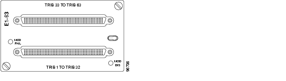
This module contains 63 E1 interfaces. The E1 traffic is mapped into VC-12 containers and multiplexed together according to chapter 5.1.1 Multiplexing Structure and Mapping modes, page 5-1. As shown in Figure 14-1 two high density LFH type connectors are used to interface the 63 E1's, 32 interfaces in the bottom connector and 31 interfaces in the top connector (one pair left unconnected). This module supports transparent data (G.703) and ISDN PRA.
Figure 14-1 High Density 63xE1 Module, E1-63
14.1.1 Power Consumption
The module power consumption is 21 W.
14.1.2 Connectors
The connector is a high density LFH connector with pin-out as described in Table 14-1 and Table 14-2.
Table 14-1 Multi-interface Lower connector - Pinout
Pin
|
Signal
|
Pin
|
Signal
|
Pin
|
Signal
|
Pin
|
Signal
|
1
|
RxD29-
|
41
|
RxD2-
|
81
|
RxD31-
|
121
|
RxD4-
|
2
|
RxD29+
|
42
|
RxD2+
|
82
|
RxD31+
|
122
|
RxD4+
|
3
|
GND
|
43
|
GND
|
83
|
GND
|
123
|
GND
|
4
|
TxD29-
|
44
|
TxD2-
|
84
|
TxD31-
|
124
|
TxD4-
|
5
|
TxD29+
|
45
|
TxD2+
|
85
|
TxD31+
|
125
|
TxD4+
|
6
|
TxD25-
|
46
|
TxD6-
|
86
|
TxD27-
|
126
|
TxD8-
|
7
|
TxD25+
|
47
|
TxD6+
|
87
|
TxD27+
|
127
|
TxD8+
|
8
|
GND
|
48
|
GND
|
88
|
GND
|
128
|
GND
|
9
|
RxD25-
|
49
|
RxD6-
|
89
|
RxD27-
|
129
|
RxD8-
|
10
|
RxD25+
|
50
|
RxD6+
|
90
|
RxD27+
|
130
|
RxD8+
|
11
|
RxD21-
|
51
|
RxD10-
|
91
|
RxD23-
|
131
|
RxD12-
|
12
|
RxD21+
|
52
|
RxD10+
|
92
|
RxD23+
|
132
|
RxD12+
|
13
|
GND
|
53
|
GND
|
93
|
GND
|
133
|
GND
|
14
|
TxD21-
|
54
|
TxD10-
|
94
|
TxD23-
|
134
|
TxD12-
|
15
|
TxD21+
|
55
|
TxD10+
|
95
|
TxD23+
|
135
|
TxD12+
|
16
|
TxD17-
|
56
|
TxD14-
|
96
|
TxD19-
|
136
|
TxD16-
|
17
|
TxD17+
|
57
|
TxD14+
|
97
|
TxD19+
|
137
|
TxD16+
|
18
|
GND
|
58
|
GND
|
98
|
GND
|
138
|
GND
|
19
|
RxD17-
|
59
|
RxD14-
|
99
|
RxD19-
|
139
|
RxD16-
|
20
|
RxD17+
|
60
|
RxD14+
|
100
|
RxD19+
|
140
|
RxD16+
|
21
|
RxD13-
|
61
|
RxD18-
|
101
|
RxD15-
|
141
|
RxD20-
|
22
|
RxD13+
|
62
|
RxD18+
|
102
|
RxD15+
|
142
|
RxD20+
|
23
|
GND
|
63
|
GND
|
103
|
GND
|
143
|
GND
|
24
|
TxD13-
|
64
|
TxD18-
|
104
|
TxD15-
|
144
|
TxD20-
|
25
|
TxD13+
|
65
|
TxD18+
|
105
|
TxD15+
|
145
|
TxD20+
|
26
|
TxD9-
|
66
|
TxD22-
|
106
|
TxD11-
|
146
|
TxD24-
|
27
|
TxD9+
|
67
|
TxD22+
|
107
|
TxD11+
|
147
|
TxD24+
|
28
|
GND
|
68
|
GND
|
108
|
GND
|
148
|
GND
|
29
|
RxD9-
|
69
|
RxD22-
|
109
|
RxD11-
|
149
|
RxD24-
|
30
|
RxD9+
|
70
|
RxD22+
|
110
|
RxD11+
|
150
|
RxD24+
|
31
|
RxD5-
|
71
|
RxD26-
|
111
|
RxD7-
|
151
|
RxD28-
|
32
|
RxD5+
|
72
|
RxD26+
|
112
|
RxD7+
|
152
|
RxD28+
|
33
|
GND
|
73
|
GND
|
113
|
GND
|
153
|
GND
|
34
|
TxD5-
|
74
|
TxD26-
|
114
|
TxD7-
|
154
|
TxD28-
|
35
|
TxD5+
|
75
|
TxD26+
|
115
|
TxD7+
|
155
|
TxD28+
|
36
|
TxD1-
|
76
|
TxD30-
|
116
|
TxD3-
|
156
|
TxD32-
|
37
|
TxD1+
|
77
|
TxD30+
|
117
|
TxD3+
|
157
|
TxD32+
|
38
|
GND
|
78
|
GND
|
118
|
GND
|
158
|
GND
|
39
|
RxD1-
|
79
|
RxD30-
|
119
|
RxD3-
|
159
|
RxD32-
|
40
|
RxD1+
|
80
|
RxD30+
|
120
|
RxD3+
|
160
|
RxD32+
|
Table 14-2 Multi-interface Upper connector - Pinout
Pin
|
Signal
|
Pin
|
Signal
|
Pin
|
Signal
|
Pin
|
Signal
|
1
|
RxD61-
|
41
|
RxD34-
|
81
|
RxD63-
|
121
|
RxD36-
|
2
|
RxD61+
|
42
|
RxD34+
|
82
|
RxD63+
|
122
|
RxD36+
|
3
|
GND
|
43
|
GND
|
83
|
GND
|
123
|
GND
|
4
|
TxD61-
|
44
|
TxD34-
|
84
|
TxD63-
|
124
|
TxD36-
|
5
|
TxD61+
|
45
|
TxD34+
|
85
|
TxD63+
|
125
|
TxD36+
|
6
|
TxD57-
|
46
|
TxD38-
|
86
|
TxD59-
|
126
|
TxD40-
|
7
|
TxD57+
|
47
|
TxD38+
|
87
|
TxD59+
|
127
|
TxD40+
|
8
|
GND
|
48
|
GND
|
88
|
GND
|
128
|
GND
|
9
|
RxD57-
|
49
|
RxD38-
|
89
|
RxD59-
|
129
|
RxD40-
|
10
|
RxD57+
|
50
|
RxD38+
|
90
|
RxD59+
|
130
|
RxD40+
|
11
|
RxD53-
|
51
|
RxD42-
|
91
|
RxD55-
|
131
|
RxD44-
|
12
|
RxD53+
|
52
|
RxD42+
|
92
|
RxD55+
|
132
|
RxD44+
|
13
|
GND
|
53
|
GND
|
93
|
GND
|
133
|
GND
|
14
|
TxD53-
|
54
|
TxD42-
|
94
|
TxD55-
|
134
|
TxD44-
|
15
|
TxD53+
|
55
|
TxD42+
|
95
|
TxD55+
|
135
|
TxD44+
|
16
|
TxD49-
|
56
|
TxD46-
|
96
|
TxD51-
|
136
|
TxD48-
|
17
|
TxD49+
|
57
|
TxD46+
|
97
|
TxD51+
|
137
|
TxD48+
|
18
|
GND
|
58
|
GND
|
98
|
GND
|
138
|
GND
|
19
|
RxD49-
|
59
|
RxD46-
|
99
|
RxD51-
|
139
|
RxD48-
|
20
|
RxD49+
|
60
|
RxD46+
|
100
|
RxD51+
|
140
|
RxD48+
|
21
|
RxD45-
|
61
|
RxD50-
|
101
|
RxD47-
|
141
|
RxD52-
|
22
|
RxD45+
|
62
|
RxD50+
|
102
|
RxD47+
|
142
|
RxD52+
|
23
|
GND
|
63
|
GND
|
103
|
GND
|
143
|
GND
|
24
|
TxD45-
|
64
|
TxD50-
|
104
|
TxD47-
|
144
|
TxD52-
|
25
|
TxD45+
|
65
|
TxD50+
|
105
|
TxD47+
|
145
|
TxD52+
|
26
|
TxD41-
|
66
|
TxD54-
|
106
|
TxD43-
|
146
|
TxD56-
|
27
|
TxD41+
|
67
|
TxD54+
|
107
|
TxD43+
|
147
|
TxD56+
|
28
|
GND
|
68
|
GND
|
108
|
GND
|
148
|
GND
|
29
|
RxD41-
|
69
|
RxD54-
|
109
|
RxD43-
|
149
|
RxD56-
|
30
|
RxD41+
|
70
|
RxD54+
|
110
|
RxD43+
|
150
|
RxD56+
|
31
|
RxD37-
|
71
|
RxD58-
|
111
|
RxD39-
|
151
|
RxD60-
|
32
|
RxD37+
|
72
|
RxD58+
|
112
|
RxD39+
|
152
|
RxD60+
|
33
|
GND
|
73
|
GND
|
113
|
GND
|
153
|
GND
|
34
|
TxD37-
|
74
|
TxD58-
|
114
|
TxD39-
|
154
|
TxD60-
|
35
|
TxD37+
|
75
|
TxD58+
|
115
|
TxD39+
|
155
|
TxD60+
|
36
|
TxD33-
|
76
|
TxD62-
|
116
|
TxD35-
|
156
|
|
37
|
TxD33+
|
77
|
TxD62+
|
117
|
TxD35+
|
157
|
|
38
|
GND
|
78
|
GND
|
118
|
GND
|
158
|
GND
|
39
|
RxD33-
|
79
|
RxD62-
|
119
|
RxD35-
|
159
|
|
40
|
RxD33+
|
80
|
RxD62+
|
120
|
RxD35+
|
160
|
|
14.1.3 Compliance
Multi-Interface E1 Compliance is given in Table 14-3.
Table 14-3 Multi-Interface E1 Compliance
Standard
|
Comment
|
ETS 300 011
|
Impedance towards ground
Tolerable longitudinal voltage
|
ETS 300 126
|
Output signal balance
|
ITU-T G.703
|
Cable attenuation
Input reflection loss
Input port immunity against reflection
Output pulse mask
|
ITU-T G.783
|
Output jitter in the absence of input jitter
Output combined jitter
|
ITU-T G.823
|
Max. tolerable input jitter
|
14.2 Patch Panels
Two types of patch panels and a LFH cable are available for patching the 63 E1's interface on the High Density 63xE1 module.Please see the following sections for details.
Warning  This interface is considered SELV circuit. Avoid connecting this interface to TNV circuits. The cables must not run with power cables, Network cables, or any other cables which are not connected to SELV circuits. The electrical cables must not exit the building. If cables are connected to an equipment which contains not SELV circuits, proper insulation between the ONS15305 E1 cables interface and the other equipment interfaces must be provided.
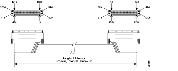
14.2.1 32XE1 LFH - LFH Cable
The patch cable is depicted in Figure 14-2.
Available patch cable length:
•3 M
•10 M
•25 M.
Figure 14-2 32XE1 LFH - LFH Cable
Warning To protect the cable jacket, avoid sharp edges and excessive bending. Always fasten the cable connectors with both fixing screws. If the connector is fixed with one screw only, this screw is likely to break if the cable is pulled by accident.
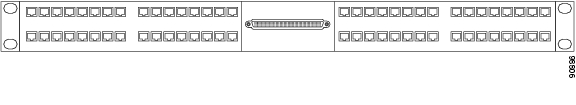
14.2.2 32xE1-LFH-RJ45 Panel
Figure 14-3 32xE1-LFH-RJ45 Panel
The RJ45 patch panel shown in Figure 14-3 provide an interface with impedance 120 ohm.
14.2.2.1 Pinout
Table 14-4 RJ-45 Connector - Pinout
Pin
|
Signal
|
1
|
P120 OUT
|
2
|
N120 OUT
|
3
|
GND
|
4
|
P120 IN
|
5
|
N120 IN
|
6
|
SHIELD
|
7
|
NC
|
8
|
NC
|
RJ-45 Connector - Pinout is described in Table 14-4.
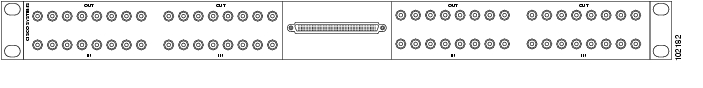
14.2.3 32xE1-LFH-1.0/2.3 Panel
This is a patch panel for the multi interface E1 connector. One connector can have up to 32 E1 interfaces.
The patch panel have 32 1.0/2.3 connectors for the E1 interfaces and one LFH connector for connection to the module. See Figure 14-3. The patch panel interface impedance is 75 Ohm. Cable with predefined length (see 32XE1 LFH - LFH Cable) must be used to connect the patch panel to the multi interface E1 module. The patch panel can be mounted in 19" or ETSI racks and the height is 1U (44 mm).
32xE1-LFH-1.0/2.3 Panel