|
|

Table Of Contents
Optical Power Level Troubleshooting for the Cisco ONS 15216-MD16-2-Red/Blue 100-GHz Mux/Demux Module
1. Low Optical Power For Composite (Multiplexed) Optical Signal at Mux
2. Low Optical Power for an Individual Wavelength at Mux Common Port
3. Low Optical Power for All Individual Ports at Demux
4. Low Optical Power for Individual Port at Demux
5. Low Optical Power for Blue (Upgrade) Wavelength at Mux
6. Low Optical Power for Blue (Upgrade) Wavelengths at Demux
Obtaining Technical Assistance
Obtaining Additional Publications and Information
Optical Power Level Troubleshooting for the Cisco ONS 15216-MD16-2-Red/Blue 100-GHz Mux/Demux Module
This document provides procedures for troubleshooting the most common power problems encountered with the Cisco ONS 15216-MD16-2-Red/Blue 100-GHz mux/demux optical filters. It contains the following sections:
1. Low Optical Power For Composite (Multiplexed) Optical Signal at Mux
2. Low Optical Power for an Individual Wavelength at Mux Common Port
3. Low Optical Power for All Individual Ports at Demux
4. Low Optical Power for Individual Port at Demux
5. Low Optical Power for Blue (Upgrade) Wavelength at Mux
6. Low Optical Power for Blue (Upgrade) Wavelengths at Demux
Obtaining Technical Assistance
Obtaining Additional Publications and Information
CautionFor a system carrying live traffic, the Common Out and Common In ports of the ONS 15216 Red Dense Wavelength Division Multiplexing (DWDM) Base Unit carry multiplexed aggregate signals. Also, the upgrade connections of the ONS 15216 Blue DWDM Upgrade Unit (To Base1, To Base 2, From Base 1, and From Base 2), when connected to the ONS 15216 Red DWDM Base Unit (From Upgrade 1, From Upgrade 2, To Upgrade 1, and To Upgrade 2, respectively) carry multiplexed aggregate signals. Major service interruptions occur if these connections are tampered with during troubleshooting. Any work on these connections should be undertaken during a maintenance window.
Note
1. Low Optical Power For Composite (Multiplexed) Optical Signal at Mux
Symptom Because of the typical use of the mux/demux product, low optical power for composite (multiplexed) optical signals is most easily identified from the far end of a particular link.
Possible Cause Many factors outside of the operation of the mux/demux device, such as faulty patch cords, faulty connectors on a patch panel, and atypically high loss across outside plant/network fiber, could easily result in the same symptom.
The vast majority of instances of this kind of problem are due to old/faulty patch cords and/or dirty connectors. Always check connectors, patch cords, and patch cord routing before beginning diagnosis.
Recommended Action Using an OSA connected to the monitor port of the mux device, verify total channel optical power uniformity.
Note
Step 1
Step 2
Step 3
2. Low Optical Power for an Individual Wavelength at Mux Common Port
Symptom Because of the typical use of the mux/demux product, low optical power for an individual wavelength at the mux Common port is most easily identified from the far end of a particular link.
Possible Cause Many different factors outside of the operation of the mux/demux device, such as faulty patch cords, faulty connectors on a patch panel, and atypically high loss across outside plant/network fiber, could easily result in the same symptom.
The vast majority of instances of this kind of problem are due to old/faulty patch cords and/or dirty connectors. Always check connectors, patch cords, and patch cord routing before beginning diagnosis.
Recommended Action Using an OSA connected to the monitor port of the mux device, determine which individual wavelength or wavelengths are exhibiting high insertion loss.
Note
Step 1
Step 2
Step 3
3. Low Optical Power for All Individual Ports at Demux
Symptom Low optical power is exhibited for all individual ports at demux.
Possible Cause The vast majority of instances of low optical power for all individual ports at demux are due to old/faulty patch cords and/or dirty connectors. Always check connectors, patch cords, and patch cord routing before beginning diagnosis.
Many different factors outside of the operation of the mux/demux device, such as faulty patch cords, faulty connectors on a patch panel, and atypically high loss across outside plant/network fiber, could easily result in the same symptom.
Recommended Action Using an OSA connected to the monitor port of the demux device, verify total channel optical power uniformity.
Note
Step 1
Step 2
Step 3
4. Low Optical Power for Individual Port at Demux
Symptom Low optical power is exhibited for an individual port at demux.
Possible Cause The vast majority of instances of low optical power for an individual port at demux are due to old/faulty patch cords and/or dirty connectors. Always check connectors, patch cords, and patch cord routing before beginning diagnosis.
Many factors outside of the operation of the mux/demux device, such as faulty patch cords, faulty connectors on a patch panel, and atypically high loss across outside plant/network fiber, could easily result in the same symptom.
Recommended Action Using an OSA connected to the monitor port of the demux device, determine which individual wavelength or wavelengths are exhibiting high insertion loss.
Note
At the individual wavelength drop port, verify that the optical patch cord used to connect the receiver to the demux device is free of defects, and that the connectors are clean, fully seated, and free of scratches.
5. Low Optical Power for Blue (Upgrade) Wavelength at Mux
Symptom Because of the typical use of the mux/demux product, low power for a blue (upgrade) wavelength at mux is most easily identified from the far end of a particular link.
Possible Cause The vast majority of instances of low power for a blue (upgrade) wavelength at mux are due to old/faulty patch cords and/or dirty connectors. Always check connectors, patch cords, and patch cord routing before beginning diagnosis.
Many factors outside of the operation of the mux/demux device, such as faulty patch cords, faulty connectors on a patch panel, and atypically high loss across outside plant/network fiber, could easily result in the same symptom.
Recommended Action Using an OSA connected to the monitor port of the mux device, determine which individual wavelength or wavelengths are exhibiting high insertion loss.
Note
Step 1
Step 2
Step 3
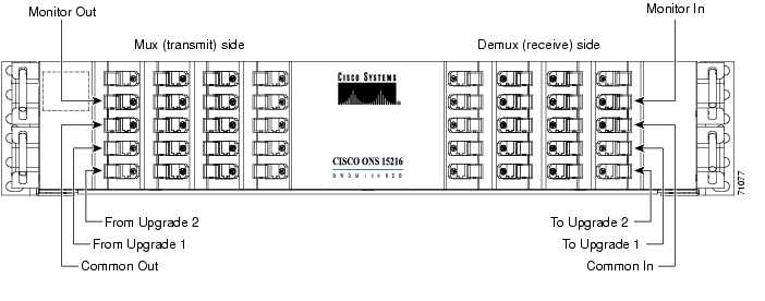
Figure 1 Front Panel of the ONS 15216 Red DWDM Base Unit
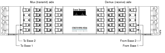
Figure 2 Front Panel of the ONS 15216 Blue DWDM Upgrade Unit
6. Low Optical Power for Blue (Upgrade) Wavelengths at Demux
Symptom Optical power is low for blue (upgrade) wavelengths at demux.
Possible Cause The vast majority of instances of low optical power for blue wavelengths at demux are due to old/faulty patch cords and/or dirty connectors. Always check connectors, patch cords, and patch cord routing before beginning diagnosis.
Many factors outside of the operation of the mux/demux device, such as faulty patch cords, faulty connectors on a patch panel, and atypically high loss across outside plant/network fiber, could easily result in the same symptom.
Recommended Action Using an OSA connected to the monitor port of the demux device, determine which individual wavelength or wavelengths are exhibiting high insertion loss.
Note
Step 1
Step 2
Step 3
Obtaining Documentation
Cisco provides several ways to obtain documentation, technical assistance, and other technical resources. These sections explain how to obtain technical information from Cisco Systems.
Cisco.com
You can access the most current Cisco documentation on the World Wide Web at this URL:
http://www.cisco.com/univercd/home/home.htm
You can access the Cisco website at this URL:
International Cisco websites can be accessed from this URL:
http://www.cisco.com/public/countries_languages.shtml
Documentation CD-ROM
Cisco documentation and additional literature are available in a Cisco Documentation CD-ROM package, which may have shipped with your product. The Documentation CD-ROM is updated regularly and may be more current than printed documentation. The CD-ROM package is available as a single unit or through an annual or quarterly subscription.
Registered Cisco.com users can order a single Documentation CD-ROM (product number DOC-CONDOCCD=) through the Cisco Ordering tool:
http://www.cisco.com/en/US/partner/ordering/ordering_place_order_ordering_tool_launch.html
All users can order annual or quarterly subscriptions through the online Subscription Store:
http://www.cisco.com/go/subscription
Ordering Documentation
You can find instructions for ordering documentation at this URL:
http://www.cisco.com/univercd/cc/td/doc/es_inpck/pdi.htm
You can order Cisco documentation in these ways:
•
http://www.cisco.com/en/US/partner/ordering/index.shtml
•
Documentation Feedback
You can submit comments electronically on Cisco.com. On the Cisco Documentation home page, click Feedback at the top of the page.
You can send your comments in e-mail to bug-doc@cisco.com.
You can submit comments by using the response card (if present) behind the front cover of your document or by writing to the following address:
Cisco Systems
Attn: Customer Document Ordering
170 West Tasman Drive
San Jose, CA 95134-9883We appreciate your comments.
Obtaining Technical Assistance
For all customers, partners, resellers, and distributors who hold valid Cisco service contracts, the Cisco Technical Assistance Center (TAC) provides 24-hour, award-winning technical support services, online and over the phone. Cisco.com features the Cisco TAC website as an online starting point for technical assistance.
Cisco TAC Website
The Cisco TAC website ( http://www.cisco.com/tac) provides online documents and tools for troubleshooting and resolving technical issues with Cisco products and technologies. The Cisco TAC website is available 24 hours a day, 365 days a year.
Accessing all the tools on the Cisco TAC website requires a Cisco.com user ID and password. If you have a valid service contract but do not have a login ID or password, register at this URL:
http://tools.cisco.com/RPF/register/register.do
Opening a TAC Case
The online TAC Case Open Tool ( http://www.cisco.com/tac/caseopen) is the fastest way to open P3 and P4 cases. (Your network is minimally impaired or you require product information). After you describe your situation, the TAC Case Open Tool automatically recommends resources for an immediate solution. If your issue is not resolved using these recommendations, your case will be assigned to a Cisco TAC engineer.
For P1 or P2 cases (your production network is down or severely degraded) or if you do not have Internet access, contact Cisco TAC by telephone. Cisco TAC engineers are assigned immediately to P1 and P2 cases to help keep your business operations running smoothly.
To open a case by telephone, use one of the following numbers:
Asia-Pacific: +61 2 8446 7411 (Australia: 1 800 805 227)
EMEA: +32 2 704 55 55
USA: 1 800 553-2447For a complete listing of Cisco TAC contacts, go to this URL:
http://www.cisco.com/warp/public/687/Directory/DirTAC.shtml
TAC Case Priority Definitions
To ensure that all cases are reported in a standard format, Cisco has established case priority definitions.
Priority 1 (P1)—Your network is "down" or there is a critical impact to your business operations. You and Cisco will commit all necessary resources around the clock to resolve the situation.
Priority 2 (P2)—Operation of an existing network is severely degraded, or significant aspects of your business operation are negatively affected by inadequate performance of Cisco products. You and Cisco will commit full-time resources during normal business hours to resolve the situation.
Priority 3 (P3)—Operational performance of your network is impaired, but most business operations remain functional. You and Cisco will commit resources during normal business hours to restore service to satisfactory levels.
Priority 4 (P4)—You require information or assistance with Cisco product capabilities, installation, or configuration. There is little or no effect on your business operations.
Obtaining Additional Publications and Information
Information about Cisco products, technologies, and network solutions is available from various online and printed sources.
•
http://www.cisco.com/en/US/products/products_catalog_links_launch.html
•
•
http://www.cisco.com/go/packet
•
http://www.cisco.com/go/iqmagazine
•
http://www.cisco.com/en/US/about/ac123/ac147/about_cisco_the_internet_protocol_journal.html
•
http://www.cisco.com/en/US/learning/index.html
Copyright © 2003 Cisco Systems, Inc. All rights reserved.
![]()
![]()
![]()
![]()
![]()
![]()
![]()
![]()
Posted: Sun Apr 2 04:13:33 PDT 2006
All contents are Copyright © 1992--2006 Cisco Systems, Inc. All rights reserved.
Important Notices and Privacy Statement.