|
|

Table Of Contents
Installing the Cisco ONS 15216
100 GHz DWDM FiltersFiber Optic Connector Cleaning and Maintenance
Customer Supplied Cleaning Materials
Fiber Optic Cable Installation
Adding Wavelengths (Upgrading)
Installing the Cisco ONS 15216
100 GHz DWDM Filters
Overview
This document contains functional and physical descriptions as well as instructions for installing the Cisco ONS 15216 DWDM filters. The ONS 15216 has two separate rack mounted filter assemblies, a red base unit and a blue upgrade unit. The filters mount in a 19- or 23-inch rack and occupy 2 RU. The ONS 15216 filters are intended for use with the ONS 15454 DWDM ITU optics cards but can be used with other optical equipment with laser outputs that follow the ITU 100 GHz optics plan.
Red Base Unit
The ONS 15216 Red DWDM base unit is a passive filter comprised of an ITU-compliant 100 GHz unidirectional 16x1 multiplexer (mux) and a 100 GHz unidirectional 1x16 demultiplexer (demux) that operate at the following wavelengths: 1546.12 nm, 1546.92 nm, 1547.72 nm, 1548.51 nm, 1550.12 nm, 1550.92 nm, 1551.72 nm 1552.52 nm, 1554.13 nm, 1554.94 nm, 1555.75 nm, 1556.55 nm, 1558.17 nm, 1558.98 nm, 1559.79 nm, and 1560.61 nm.
The base unit also features a 100-to-200 GHz interleaver and red/blue band splitters (couplers) with two corresponding pairs of blue upgrade ports that connect the blue upgrade unit to the red base unit. The blue upgrade ports on the red base unit can support wavelengths from 1530.33 nm to 1544.53 nm. This allows growth of up to 32 wavelengths on a single fiber pair.
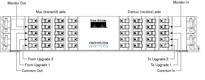
The ONS 15216 base unit has sixteen mux ports and sixteen demux ports. The unit also has a pair of monitor ports (outputs) that allows the user to monitor the signals in the common transmit and receive fibers in a non-intrusive manner. The monitor ports use a 2%/98% tap splitter on the transmitter (mux) side and a 2%/98% tap splitter on the receiver (demux) side. The Common In port connects fiber into the base unit. Outgoing fiber connects to the Common Out port. The base unit connects to the upgrade unit through the To Upgrade 1, To Upgrade 2, From Upgrade 1, and From Upgrade 2 ports. Figure 1 shows the front panel of the red base unit.
Figure 1 Front Panel of the ONS 15216 Red DWDM Base Unit
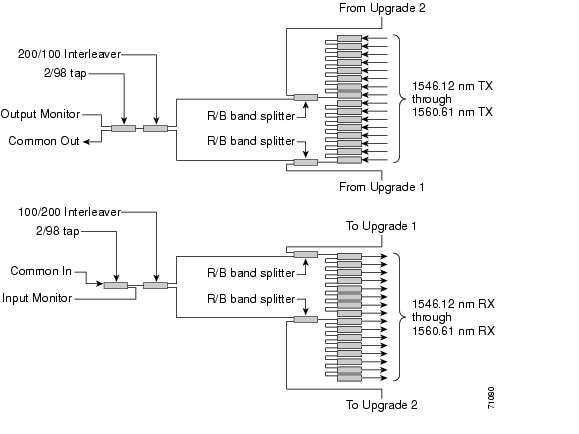
The red base unit is divided into two halves: mux and demux. The mux half is the transmit side and the demux half is the receive side. Figure 2 is a block diagram that shows the functional layout of the red base unit.Figure 2 Block Diagram of the ONS 15216 Red DWDM Base Unit
Blue Upgrade Unit
The ONS 15216 Blue DWDM upgrade unit is a passive filter consisting of an ITU-compliant 100 GHz unidirectional 16x1 mux and a 100 GHz unidirectional 1x16 demux that operate at the following wavelengths: 1530.33 nm, 1531.12 nm, 1531.90 nm, 1532.68 nm, 1534.25 nm, 1535.04 nm, 1538.52 nm, 1536.61 nm, 1538.19 nm, 1538.98 nm, 1539.77 nm, 1540.56 nm, 1542.14 nm, 1542.94 nm, 1543.73 nm, and 1544.53 nm.
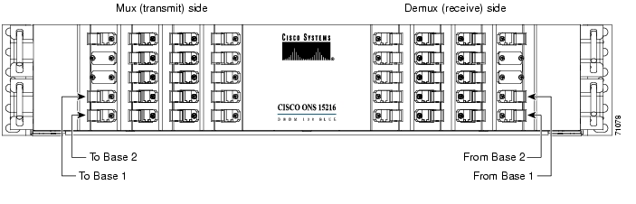
The ONS 15216 upgrade unit has sixteen mux ports and sixteen demux ports. The To Base 1 port connects fiber into the From Upgrade 1 port of the base unit. The To Base 2 port connects fiber into the From Upgrade 2 port of the base unit. The From Base 1 port connects fiber into the To Upgrade 1 of the base unit. The From Base 2 port connects fiber into the To Upgrade 2 port of the base unit.
Figure 3 shows the front panel of the blue upgrade unit.
Figure 3 Front Panel of the ONS 15216 Blue DWDM Upgrade Unit
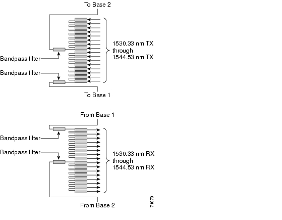
The blue upgrade unit is also divided into two halves: mux and demux. As with the red base unit, the mux half is the transmit side and the demux half is the receive side. Figure 4 is a block diagram that shows the functional layout of the blue upgrade unit.Figure 4 Block Diagram of the ONS 15216 Blue DWDM Base Unit
Physical Description
Both the red base unit and the blue upgrade unit are housed in 2 RU, 19 inch rack mounted assemblies and measure 3.5-in. high by 17.21-in. wide by 11-in. deep. The connectors on both filters are SC bulkhead adapters. As you face the unit, the connectors on the left-hand side are the mux (transmit) connectors and the connectors on the right hand side are the demux (receive) connectors. The connectors are labeled with the corresponding wavelength or function. A retractable tray located under the front panel contains a port map to help you identify port locations.
Installation
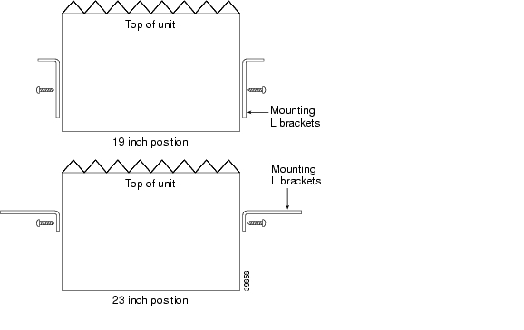
The ONS 15216 filters can be installed in a standard 19- or 23-inch equipment rack. Each assembly includes reversible mounting brackets that you can rotate to fit either rack size. The units ship with the mounting brackets in the 19-inch position. Figure 5 shows the top view of a unit with the mounting brackets in both positions.
Figure 5 Reversible Mounting Brackets
Four rack-mounting screws are included with each ONS 15216. Because the units are passive devices, no power cabling or connections are necessary. The units can be installed anywhere in the rack (in other words, above or below the DWDM generating equipment) according to local site practice.
Procedure to Install the ONS 15216
Step 1
Set the mounting brackets to either the 19- or 23-inch position, depending on the rack you are using.
Keep in mind that the units are shipped with the mounting brackets in the 19-inch position. See Figure 5 for mounting bracket positioning information.
Step 2
Step 3
Step 4
Step 5
Fiber Optic Connector Cleaning and Maintenance
Disciplined connector cleaning care is required to maintain the performance of fiber optic circuits. It is important that both the SC/UPC connector at the end of the fiber optic cable and the mating bulkhead adapter on the front panel of the ONS 15216 are clean before the connection is made.
Warning
Warning
Note
Note
Customer Supplied Cleaning Materials
The following cleaning materials are recommended but are not supplied with the ONS 15216 module:
•
•
•
When cleaning a paired cable connector (bulkhead mating adapter), always clean the mating adapter first. If properly maintained (only used with clean, defect-free fiber connectors and capped when not in use), the mating adapter should not require cleaning. However, if you suspect the adapter is dirty, clean it by blowing with clean, dry, oil-free compressed air.
Procedure to Clean the Bulkhead Mating Adapters
Step 1
Improper use of the compressed air may cause more contamination to the part being cleaned and defeat the purpose of cleaning the bulkhead mating adapters.
Step 2
Step 3
Note
Procedure to Clean Fiber Optic Cable Connectors
Step 1
Step 2
Step 3
Step 4
Note
Step 5
Step 6
Step 7
Step 8
Step 9
Step 10
Defects on the fiber cable connector are likely to damage the mating connector inside the ONS 15216, which results in more costly repairs.
Step 11
Fiber Optic Cable Installation
Warning
Warning
Note
Note
Procedure to install and route fiber optic cables to the ONS 15216
Step 1
Step 2
Step 3
Step 4
A spring-ball screw that allows the fiber guide locker to be easily opened or closed secures the top.
Step 5
Adding Wavelengths (Upgrading)
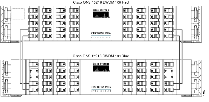
To add wavelengths, install the blue upgrade unit and connect it to the red base unit. If you need to upgrade your DWDM system (add wavelengths), use the To Base 1, To Base 2, From Base 1, and From Base 2 ports on the blue upgrade unit and the From Upgrade 1, From Upgrade 2, To Upgrade 1, and To Upgrade 2 ports on the red base unit. This provides multiplexing/demultiplexing of 32 wavelengths with two fibers.
Procedure to connect the blue upgrade unit to the red base unit
Step 1
Step 2
Step 3
Figure 6 shows the base and upgrade units interconnected.
Figure 6 Interconnected Red Base and Blue Upgrade Units
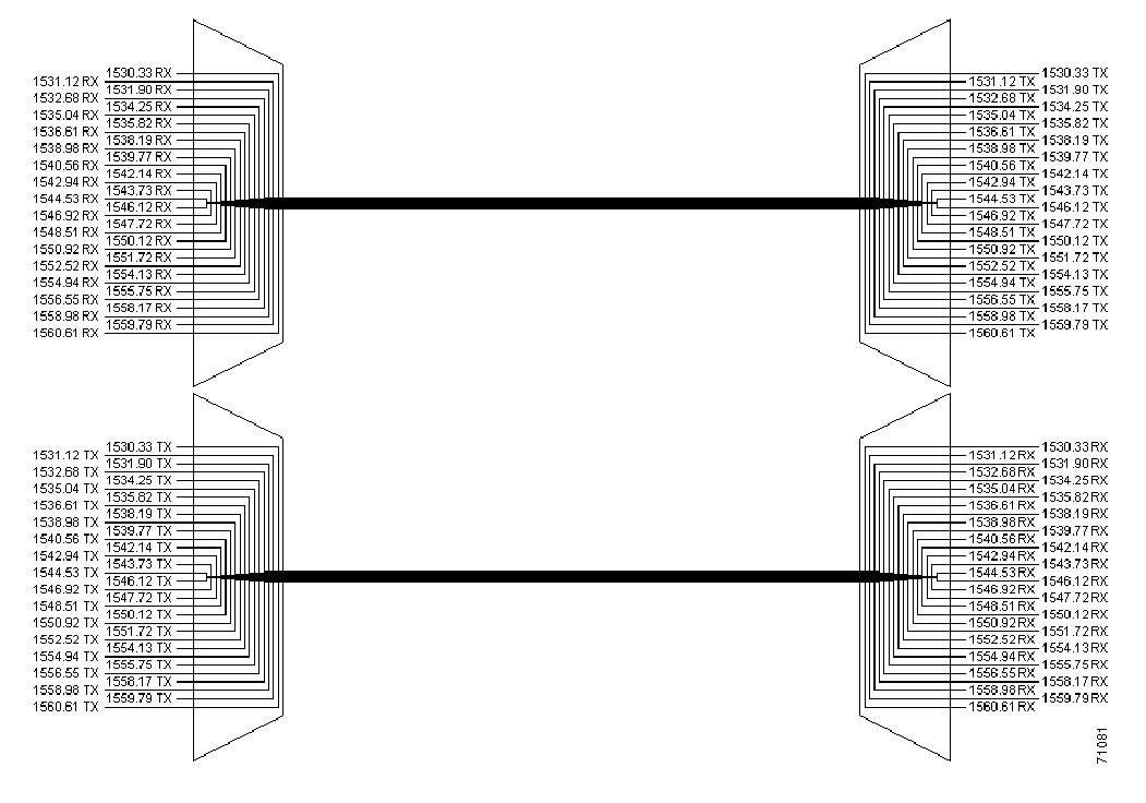
Network Requirements
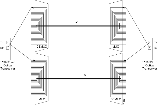
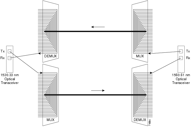
When deploying the ONS 15216 within the network, make sure that each end of the network mirrors the other. In other words, the same type of ONS 15216 filter should be installed at both ends of the fiber facilities. When you attach transmitting lasers to the ONS 15216, optical filters should comply with the ITU-T 100GHz wavelength plan. Interconnect the transmitting laser's output (transmit) port to the appropriate wavelength input port on the ONS 15216 optical filter. At the other end of the network (or fiber), connect the associated optical receiver to the corresponding wavelength output port consistent with the wavelength of the laser transmitter at the opposite end. Many optical receivers accept any input wavelength between 1310nm and 1550nm. As such, if your terminal equipment uses transceivers, your network can have mirrored optical wavelength cards. Figure 7 depicts a mirrored network using the Cisco ONS 15454 ITU optics cards connected through an ONS 15216 at each end of the network. Figure 8 shows mirrored ONS 15454 ITU optics cards connected through an ONS 15216 at each end of the network. Figure 9 shows non-mirrored ONS 15454 ITU optics cards connected through an ONS 15216 at each end of the network.
Figure 7 DWDM Mirrored Network
Figure 8 DWDM Mirrored Cards
Figure 9 DWDM Non-Mirrored Cards
Specifications
ITU Channel Plan
Center Wavelengths for the Base Red Filter (Model 15216-DWDM100-RED)
1546.12 nm
1546.92 nm
1547.72 nm
1548.51 nm
1550.12 nm
1550.92 nm
1551.72 nm
1552.52 nm
1554.13 nm
1554.94 nm
1555.75 nm
1556.55 nm
1558.17 nm
1558.98 nm
1559.79 nm
1560.61 nm
Center Wavelengths for the Upgrade Blue Filter (Model 15216-DWDM100-BLUE)
1530.33 nm
1531.12 nm
1531.90 nm
1532.68 nm
1534.25 nm
1535.04 nm
1535.82 nm
1536.61 nm
1538.19 nm
1538.98 nm
1539.77 nm
1540.56 nm
1542.14 nm
1542.94 nm
1543.73 nm
1544.53 nm
Channel Spacing
100GHz
Insertion Loss
16 Wavelength Base Red Filter: 6.2 dB maximum
Upgrade port on the Base Red Filter: 2.5 dB
16 Wavelength Upgrade Blue Filter: 3.7 dB maximum
Channel Uniformity
1.2 dB maximum @ 25ΑC
Directivity
50 dB minimum
Optical Return Loss
40 dB minimum
Polarization Mode Dispersion
0.5 ps typical
Chromatic Dispersion
10 ps maximum
Monitor Ports - Insertion Loss
Demultiplexer (2% monitor in port): 18.8 dB maximum
Multiplexer (2% monitor out port): 18.8 dB maximum
Isolation
First Adjacent: 25 dB minimum
Second Adjacent: 28 dB minimum
Other Non-adjacent : 43 dB minimum
Maximum Optical Power Input
250 mW
Temperature
Operating: 0Α to 70Α C
Storage : -40Α to 85Α C
Chassis Dimensions
Width: 17.21 in. (without mounting ears)
Height: 3.5 in.
Depth: 11 in.
Base Red Unit Weight: 18 lbs
Upgrade Blue Unit Weight: 15 lbs
Connector Type
SC/UPC
AccessPath, AtmDirector, Browse with Me, CCDA, CCDE, CCDP, CCIE, CCNA, CCNP, CCSI, CD-PAC, CiscoLink, the Cisco NetWorks logo, the Cisco Powered Network logo, Cisco Systems Networking Academy, the Cisco Systems Networking Academy logo, Fast Step, Follow Me Browsing, FormShare, FrameShare, GigaStack, IGX, Internet Quotient, IP/VC, iQ Breakthrough, iQ Expertise, iQ FastTrack, the iQ Logo, iQ Net Readiness Scorecard, MGX, the Networkers logo, Packet, RateMUX, ScriptBuilder, ScriptShare, SlideCast, SMARTnet, TransPath, Unity, Voice LAN, Wavelength Router, and WebViewer are trademarks of Cisco Systems, Inc.; Changing the Way We Work, Live, Play, and Learn, Discover All That's Possible, and Empowering the Internet Generation, are service marks of Cisco Systems, Inc.; and Aironet, ASIST, BPX, Catalyst, Cisco, the Cisco Certified Internetwork Expert logo, Cisco IOS, the Cisco IOS logo, Cisco Systems, Cisco Systems Capital, the Cisco Systems logo, Enterprise/Solver, EtherChannel, EtherSwitch, FastHub, FastSwitch, IOS, IP/TV, LightStream, MICA, Network Registrar, PIX, Post-Routing, Pre-Routing, Registrar, StrataView Plus, Stratm, SwitchProbe, TeleRouter, and VCO are registered trademarks of Cisco Systems, Inc. and/or its affiliates in the U.S. and certain other countries.
All other brands, names, or trademarks mentioned in this document or Web site are the property of their respective owners. The use of the word partner does not imply a partnership relationship between Cisco and any other company. (0104R)
Installing the Cisco ONS 15216 100 Ghz DWDM Filterss
Copyright © 2001, Cisco Systems, Inc.
All rights reserved.
![]()
![]()
![]()
![]()
![]()
![]()
![]()
![]()
Posted: Sun Apr 2 03:20:11 PDT 2006
All contents are Copyright © 1992--2006 Cisco Systems, Inc. All rights reserved.
Important Notices and Privacy Statement.