cc/td/doc/product/ong/15216/216edf
hometocprevnextglossaryfeedbacksearchhelp
PDF

Table Of Contents

Installing the ONS 15216 EDFA3

4.1  Unpacking

4.1.1  Verifying the Unpacking

4.2  Installing and Powering Up the EDFA3

4.3  Installing the AC Adapter

4.4  Verifying the Rack Installation

4.5  Connecting the Fiber to the Optical Ports


Installing the ONS 15216 EDFA3


This chapter contains information about installing the Cisco ONS 15216 EDFA3, including:

Unpacking

Installing and Powering Up the EDFA3

Installing the AC Adapter

Verifying the Rack Installation

Connecting the Fiber to the Optical Ports

4.1  Unpacking

Use the following procedure to unpack the ONS 15216 EDFA3.


Step 1 Position the box containing the ONS 15216 EDFA3 with the Cisco ONS 15216 logo right side up.

Step 2 Examine the packing material for any other signs of shipping damage. Report any damage directly to the shipping company.

Step 3 Use a utility knife to slit the packing tape on the top center and top edges of the box and open the top.

Step 4 Remove the packing material.

Step 5 Carefully lift out the ONS 15216 EDFA3 and place it on a flat surface.

Step 6 Remove the ONS 15216 EDFA3 and the desiccant (small white pouch containing a preservative) from the plastic bag. Place the ONS 15216 EDFA3 on a flat surface and discard the desiccant.

Step 7 Read the software license agreement attached to the outside of the bag.

Step 8 Remove the bag. When you remove the bag you accept the conditions of the software license agreement.


4.1.1  Verifying the Unpacking

Before you continue, check to ensure that all equipment is present and is in good working order.


Step 1 Do a visual inspection of all equipment for any obvious damage. If equipment is damaged, contact the Cisco Technical Assistance Center (Cisco TAC). Refer to the Preface for Cisco TAC contact information.

Step 2 Check that the contents of the order match what your company ordered from Cisco. If the contents do not match your order, contact Cisco Customer Service.


Tip Save all packing materials.


4.2  Installing and Powering Up the EDFA3


Warning Before performing any of the following procedures, ensure that the power is removed from the DC circuit. To ensure that all power is OFF, locate the circuit breaker on the panel board that services the DC circuit, switch the circuit breaker to the OFF position, and tape the switch handle of the circuit breaker in the OFF position.


Warning Be sure to connect ESD wrist or ankle straps prior to starting this procedure and any and all procedures where you are in contact with the rack and/or the EDFA3.


Use the following steps to install the fiber management brackets, install the ONS 15216 EDFA3 into the rack, and correctly set up the power supply:


Step 1 Set the fiber management brackets on the left-front and right-front sides the unit. Refer to Figure 4-1 for bracket positioning information.

Figure 4-1 Fiber Management Bracket Positioning

Step 2 Secure the fiber management brackets using the four fiber-management mounting screws that are included with each ONS 15216 EDFA3.

Step 3 Mount the ONS 15216 EDFA3 in the rack (19-in. or 23-in. [482-mm or 584-mm) reversible ears). The unit should have a space at least equal to the height of the ONS 15216 EDFA3 (1 RU) both above and below it.

Step 4 Connect the -48 VDC power cable to the office fuse panel (user-provided).

a. 1.5-A fusing is required (user-provided).

b. Use #18 AWG stranded wire (and wire lugs as appropriate).

Step 5 Connect Power Bus A. Connect the power cable from the office fuse panel to the Power Bus A terminals on the ONS 15216 EDFA3. See Figure 4-2 for an illustration of the connections. If you will be using the AC adapter, see the "Installing the AC Adapter" section.

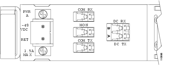
Figure 4-2 ONS 15216 EDFA3 Front Panel Connections

Step 6 Repeat Step 3 for Power Bus B, if a protection power feed is available. Otherwise, the EDFA3 can work with a single power feed.


Note If the EDFA3 is to be powered with a single power supply, Power Bus A must be used.


Step 7 Connect the facility ground to the ONS 15216 EDFA3 side panel ground using #10-32 x 3/8-inch fasteners with lock washers and ground lugs, or connect to the rear panel ground using ring lugs for #8 studs. Yellow/green striped wire must be used for the ground connection.

The crimping tool must be large enough to accommodate #10-14 AWG stranded wire or #10-12 AWG solid wire. (An example of an approved tool is the SPC Technology type CTT-8420-01 crimper which will accommodate #10-22 AWG wire.)

Step 8 Insert 1.5-A fuses into the fuse panel (user-provided).

Step 9 Untape and reactivate the circuit breaker.


4.3  Installing the AC Adapter

The ONS 15216 EDFA3 can be ordered with an AC adapter for use in locations that do not have -48-VDC electrical power available. The installation of the adapter is as follows:


Step 1 Connect the spade lugs of the AC adapter to Power Bus A of the EDFA3 unit before plugging the adapter into AC electrical power. The lug with the light blue sleeve is -48 V, while the lug with the black sleeve is the return (RTN).


Warning In case of AC adapter, single power supply on Power Bus A must be used. The AC adapter does not provide grounding; therefore, dual power supply can damage the EDFA3 by providing two potentially different voltage reference grounds.


Step 2 Connect the AC plug of the adapter to 110 to 115 VAC at 60 Hz (or 120 VAC at 50 Hz). The adapter will automatically turn on, and the EDFA3 will power up.


4.4  Verifying the Rack Installation

The Power LED on the front panel of the ONS 15216 EDFA3 illuminates when the power is supplied ( Figure 4-3).

Figure 4-3 Front Panel Power LED

4.5  Connecting the Fiber to the Optical Ports

The LC/UCP optical ports on the ONS 15216 EDFA3 are as follows:

Optical input signal to be amplified (labeled COM-RX): Input must be between -40 dBm and +12 dBm.

Optically amplified output (labeled COM-TX)

Optical monitored output signal (labeled MON): 1 percent tap of output or 20 dB below output signal

First stage output signal (labeled DC-TX)

Second stage input signal (labeled DC-RX)


Warning Follow all directions and warning labels when working with optical fibers. To prevent eye damage, never look directly into a fiber or connector.


Warning Invisible laser radiation. Do not view directly with optical instruments. Class 1m laser product.


Warning Laser specifications:
Peak power: 500 mW
Wavelength: 1528 to 1610 nm
Safety: Class 1M Laser Product per IEC/EN 60825-1/A2:2001 standard


The optical connection procedure consists of:

Cleaning the fibers

Connecting the fibers to the relative amplifier ports

Connect the customer-supplied fiber optic patch cords to the LC/UPC optical ports of the ONS 15216 EDFA3 using the following procedure. Refer to Figure 4-4 while performing this procedure.

Figure 4-4 ONS 15216 EDFA3 Optical Connections


Step 1 Clean both ends of the two fiber optic patch cords, using your site procedure. If no site procedure exists, refer to the Cisco document "Cleaning Procedure for Fiber Optic Connectors."

Step 2 Connect a patch cord from the incoming outside plant fiber (that is, the port where the signal to be amplified is input) to the ONS 15216 EDFA3 COM-RX connector.

Step 3 Connect a patch cord from the DC-TX connector to the ONS 15216 Dispersion Compensating Unit (DCU) RX connector.

Step 4 Connect a patch cord from the ONS 15216 DCU TX port to the ONS 15216 EDFA3 DC-RX port.


Note If the DCU is not required by the network design, connect the DC-TX port and the DC-RX port with an LC loopback attenuator or an attenuating patch cord with 5 dB loss (supplied inside the package).


Step 5 Connect a patch cord from the COM-TX port to the outgoing outside plant fiber.


Note The ONS 15216 EDFA3 does not work until the LINE1RXPwrTHFailLow threshold is set (see the "7.5  Use TL1 to Set the Amplifier Alarm Thresholds" section on page 7-3).


hometocprevnextglossaryfeedbacksearchhelp

Posted: Sat Sep 16 00:30:28 PDT 2006
All contents are Copyright © 1992--2006 Cisco Systems, Inc. All rights reserved.
Important Notices and Privacy Statement.