cc/td/doc/product/ong/15216/216edf
hometocprevnextglossaryfeedbacksearchhelp
PDF

Table Of Contents

Provisioning

Login Procedure

Set the IP Address Procedure

Connect Through a Telnet Session Procedure (Optional)

Set Power Bus Mode (Simplex or Duplex)

Verify Amplifier Operational Status

Set Gain

Set Alarm Thresholds

Set Password

Save Changes

Logoff


Provisioning


This chapter discusses the provisioning procedures for the Cisco ONS 15216 EDFA2.

The provisioning procedure for the ONS 15216 is as follows:

1. Login Procedure

2. Set the IP Address Procedure

3. Connect Through a Telnet Session Procedure (Optional)

4. Set Power Bus Mode (Simplex or Duplex)

5. Verify Amplifier Operational Status

6. Set Gain

7. Set Alarm Thresholds

8. Set Password

9. Save Changes

10. Logoff

The following sections describe these steps in detail.

Login Procedure

The login process is required to establish a communication session with the ONS 15216 EDFA2. To complete the provisioning process, this communication session is mandatory.


Step 1 Connect to the RS-232 port.

Step 2 Open HyperTerminal. (HyperTerminal can be found in the Microsoft Windows Accessories menu.)

Step 3 Log in by entering a user name and password as described in the "RS-232 Connection Procedure" section on page 3-7.) Example 4-1 shows the ONS 15216 EDFA2 Optical Amplifier Login window.

Step 4 If the user name or password is not correct, the user is returned to the user name prompt. Example 4-2 displays the login response.


Example 4-1 ONS 15216 EDFA2 Optical Amplifier Login Window

-- LOGIN ---------------------------------------------------- user name


ONS15216 EDFA2 Optical Amplifier
--------------------------------


Software Version 2.0.0

Copyright (c) 2000-2001 Cisco Systems, Inc.


user name: { }
Password: { }

[Login]

Example 4-2 Login Response

Welcome to ONS15216 EDFA2 Console (v2.0.0)

Cisco15216Edfa:ONS15216 EDFA2>

Set the IP Address Procedure

For connection of the ONS 15216 EDFA2 to a LAN, it is mandatory to set the ONS 15216 IP address. After the login step is completed, setting of the IP address is initially accomplished through a local serial communication interface (CLI) using the RS-232 port on the front of the module and a PC serial COM port.


Step 1 Use the snmp row set local cerent15216EdfaSromIpMgmtGroup command to set the IP address, subnet mask, gateway address, and host name. If you do not have an IP address, subnet mask, gateway address, or host name, contact your network administrator.

Step 2 At the command prompt, enter the snmp row set local cerent15216EdfaSromIpMgmtGroup command (displayed in Example 4-3) and press Enter.

Example 4-3 Setting IP Address, Subnet Mask, Gateway Address, and Community ID

Cisco15216Edfa:ONS15216 EDFA2> snmp row set local cerent15216EdfaSromIpMgmtGroup

cerent15216EdfaSromIpMgmtEnetAddress 0.0.0.0
cerent15216EdfaSromIpMgmtEnetSubNetMask 0.0.0.0
cerent15216EdfaSromIpMgmtDefaultRouterAddress 0.0.0.0
cerent15216EdfaSromIpMgmthost name "host name"
Cisco15216Edfa:ONS15216 EDFA2>

Because row set is being used in this command, the user is prompted row by row to enter the IP address, the subnet mask, the gateway address, and the community ID (host name).


You have now assigned the IP address to the ONS 15216 EDFA. You must save these changes prior to terminating the session. You must also reboot the system to make the IP address active. Use the processor reset command. (See the "processor reset Command" section on page 6-8.)


Connect Through a Telnet Session Procedure (Optional)

Provisioning of the ONS 15216 EDFA2 can be accomplished entirely through the RS-232 port using CLI or SNMP commands. After an IP address is assigned, it is easier to provision the ONS 15216 EDFA2 using Telnet or an SNMP manager. A Telnet client is needed for CLI commands over IP. A generic SNMP manager is required for SNMP management over IP. After connecting the ONS 15216 EDFA2 to the network through its RJ-45 port, the user can configure the module to accept SNMP and CLI commands via Telnet using the following procedure:


Note To perform this procedure, the ONS 15216 EDFA2 must be connected to the network via the RJ-45 port.


Step 1 Click Start> Run.

Step 2 Type Telnet followed by the ONS 15216 EDFA2 IP address.

Step 3 Log in again, using the instructions in Login Procedure.

You are now connected via Telnet.


Set Power Bus Mode (Simplex or Duplex)

The ONS 15216 EDFA2 allows users to set a simplex (one power source-Bus A) or duplex (redundant power source-Bus A and Bus B) power bus mode. Use the snmp attribute set local cerent15216EdfaPowerBusMode command to set the desired power bus mode. The default mode is duplex. See Example 4-4.

Example 4-4 snmp row set local cerent15216EdfaCfgGroup Command

Cisco15216Edfa:ONS15216 EDFA2> snmp attribute set local cerent15216EdfaPowerBusMode simplex

Cisco15216Edfa:ONS15216 EDFA2>

Verify Amplifier Operational Status

To ensure that the amplifier is working correctly on the optical level, you must verify the amplifier operational status. Use the snmp table display local cerent15216EdfaOverallStatusGroup command to verify amplifier operational status. Example 4-5 displays the output of this command.

Example 4-5 snmp table display local cerent15216EdfaOverallStatusGroup

Cisco15216Edfa:ONS15216 EDFA2> snmp table display local cerent15216EdfaOverallStatusGroup

CLASS CERENT-15216-EDFA-MIB.cerent15216EdfaOverallStatusGroup ::=
{
cerent15216EdfaInPoweruW = 316
cerent15216EdfaInPowerdBm = -5;
cerent15216EdfaOutPowermW = 50;
cerent15216EdfaOutPowerdBm = 17;
};

The input power should be consistent with the input power measured during the optical connection procedure. See the "Optical Connection Procedure" section on page 3-6 for more information. The output power value should be 22 dB greater than the input, assuming that the default gain setting is 22 dB.


Note An input power higher than -5 dBm will return a Gain Out of Range alarm that can be cleared by correctly setting the gain value. For more information, refer to Table 2-2.


Set Gain

To ensure that the ONS 15216 EDFA2 output signal is received by the transceiver in the network element, it is important that the gain is set correctly.

The desired output power per channel is dependent on the number of channels traversed in the amplifier. The user sets the gain of the amplifier depending on the input power level, the network application, and the required receiver specifications necessary for error-free operation. Gain range is provided in Table 3-3.

To set the amplifier gain, enter the snmp attribute set local cerent15216EdfaConstGainOverallGain {<gain #>}, where <gain #> is the gain value multiplied by ten. For example, if the gain value is 20 dB, the gain # would be set to 200.


Note Prior to changing or implementing gain changes, consult with a Cisco Systems Engineer to ensure proper network operation.


Set Alarm Thresholds

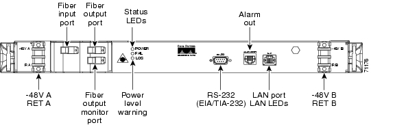
Alarm thresholds are set so that the network operator can be notified when valid alarms occur via the RJ-45 ALARM OUT and RJ-45 LAN ports on the front panel of the ONS 15216 EDFA2. (See Figure 4-1.)

Figure 4-1 ONS 15216 EDFA2 Front Panel

Alarms are reported for the following conditions:

Loss or degradation of electrical power

Pump laser overheating, excessive pump current

Loss or degradation of optical input

Alarms can be connected to a NOC NMS via a network element miscellaneous discrete input and/or office alarm panel/system.

For a full description of alarm threshold command attributes, refer to Chapter 6 SNMP commands.

To display the alarm thresholds, use the snmp table display local cerent 15216EdfaCfgGroup command ( Example 4-6). This command returns the current alarm threshold default values.

Example 4-6 snmp table display local cerent15216EdfaCfgGroup Command

Cisco15216Edfa:ONS15216 EDFA2> snmp table display local cerent15216EdfaCfgGroup

CLASS CERENT-15216-EDFA-MIB.cerent15216EdfaCfgGroup ::=
{
cerent15216EdfaCfgSaved = false;
cerent15216EdfaLpoutSetpoint = 0;
cerent15216EdfaLpoutDeviation = 200;
cerent15216EdfaLpoutHysteresis = 100;
cerent15216EdfaLOSThreshold = -2600;
cerent15216EdfaLOSHysteresis = 100;
cerent15216EdfaCtmpMin = -5;
cerent15216EdfaCtmpMinHysteresis = 1;
cerent15216EdfaCtmpMax = 65;
cerent15216EdfaCtmpMaxHysteresis = 1;
cerent15216EdfaCLEI = "";
cerent15216EdfaPowerBusMode = duplex;
cerent15216EdfaPowerBusDCVoltageMin = 400;
cerent15216EdfaPowerBusDCVoltageMax = 570;
};
Cisco15216Edfa:ONS15216 EDFA2>

To set the alarm thresholds, use the snmp row set local cerent15216EdfaCfgGroup command. After this command is entered, the user is prompted to modify each attribute, row by row, until all attributes are set. Alarm threshold attributes are described in Table 4-1.

Table 4-1 Alarm Threshold Attribute Definitions 

Attribute
Variable Definition
Syntax
Maximum Access
Description

cerent15216EdfaCfgSaved

Configuration Saved Status

True Value

Read-only

Indicates whether the current configuration has been saved. The value can be true or false. If false, the configuration is not saved.

cerent15216EdfaLpoutSetpoint

Loss of Output Power Setpoint

Integer
(0 to 1000)

Read-only

Can be disregarded when operating amplifier in factory default, constant gain mode. Setpoint object is only valid when amplifier is used in constant output power modes of operation.

cerent15216EdfaLpoutDeviation

Loss of Power Output Deviation

Integer
(0 to 1000)

Read-write

Can be disregarded when operating amplifier in factory default, constant gain mode. Deviation object is only valid when amplifier is used in constant output power modes of operation.

cerent15216EdfaLpoutHysteresis

Loss of Power Output Hysteresis

Integer
(0 to 1000)

Read-write

Can be disregarded when operating amplifier in factory default, constant gain mode. Hysteresis object is only valid when amplifier is used in constant output power modes of operation.

cerent15216EdfaLOSThreshold

Loss of Input Signal Threshold

Integer
(-3100 to -1500)

Read-write

Notifies operations personnel if the optical input signal of the ONS 15216 EDFA2 drops below a level that impacts proper operation of optical network. Set this attribute at a value that is appropriate for the intended application so that the alarm condition is meaningful. Consult with a Cisco Systems Engineer to determine the threshold value for your application. As a guideline, Cisco recommends setting the threshold value at 3 dBm below the current input power level of the amplifier. Valid entries are between -3100 and -1500 dBm times 100. For example, if the total input power of the amplifier is -24 dBm and the loss of input power threshold required is -27 dBm, the loss of input power alarm threshold is -2700.

cerent15216EdfaLOSHysteresis

Loss of Input Signal Hysteresis

Integer
(0 to 1000)

Read-write

Used to set the amount the input signal must increase above the LOS Threshold level before the alarm is cleared. This attribute, in conjunction with the loss of input signal alarm threshold, enables efficient clearing of alarms. Set this attribute at a value that is appropriate for the application so that the alarm condition will clear when input is stable. Consult with Cisco Systems Engineer to determine the correct value for your application. As a guideline, Cisco recommends setting the value 1 dBm above the LOS Threshold value. With this setting, the module will clear the alarm if it detects a signal level of 1 dBm above the current LOS Threshold value. Valid entries are between 0 and 1000 and are in dBm times 100. For example, if the hysteresis required is 1 dBm, the power alarm hysteresis is 100.

cerent15216EdfaCtmpMin

Case temperature minimum

Integer
(-10 to 10)

Read-write

Notifies operations personnel notification if the case temperature of the ONS 15216 EDFA2 drops below a level that impacts proper operation of the optical network. The minimum case temperature should be set at a value that is appropriate for the intended application and within product specifications. Users should consult with a Cisco Systems Engineer to determine the threshold value for their application. As a guideline, Cisco recommends that minimum case temperature be set at 1°C. Valid entries are between -10 and 10°C.

cerent15216EdfaPowerBusDCVoltageMin

Power bus voltage minimum

Integer
(0 to 70)

Read-write

Minimum allowable power bus DC voltage. The default minimum power bus voltage is set at -40 VDC. Valid entries are between 0 and 70 and are in volts times 10. For example, if the voltage required is -50 VDC, the power bus DC voltage is 500.

cerent15216EdfaPowerBusDCVoltageMax

Power bus voltage maximum

Integer
(0 to 70)

Read-write

Maximum allowable power bus DC voltage. The default maximum power bus voltage is set at -57 VDC. For example, if the voltage required is -50 VDC, the power bus DC voltage is 500.

cerent15216EdfaCtmpMinHysteresis

Case Temperature Hysteresis

Integer
(0 to 10)

Read-write

Used to set the amount the case temperature of the module must rise above the minimum case temperature alarm level before the alarm is cleared. This attribute, in conjunction with the case temperature minimum, enables efficient clearing of alarms. Set the hysteresis at a value that is appropriate for the application so that the alarm condition will clear when the input is stable. The user should consult with Cisco Systems Engineer in order to determine the value for their application. As a guideline, Cisco recommends that the hysteresis value be set at 1°C. Valid entries are between 0 and 10°C.

cerent15216EdfaCtmpMax


Integer
(20 to 70)

Read-write

Notifies operations personnel if the case temperature of the ONS 15216 EDFA2 is at a level that may impact proper operation of the optical network. Set the maximum case temperature at a value that is appropriate for intended application and within product specifications. Consult with a Cisco Systems Engineer to determine the threshold value for your application. As a guideline, Cisco recommends that minimum case temperature value be set at 50°C. Valid entries are between 20 and 70°C.

cerent15216EdfaCtmpMaxHysteresis


Integer
(0 to 10)

Read-write

Used to set the amount the case temperature of module must drop below the maximum case temperature alarm level before the alarm is cleared. This attribute, in conjunction with the case temperature minimum, enables efficient clearing of alarms. Set the hysteresis at a value that is appropriate for the application. If an alarm occurs, the case temperature must return to 1oC below the set value to clear the alarm. Consult with a Cisco Systems Engineer to determine the value for your application. As a guideline, Cisco recommends setting the value at 1°C. Valid entries are between 0 and 10°C. Setting this value to 0 disables this option.

cerent15216EdfaCLEI


Display String
(0 to 10 characters)

Read-only

Indicates the factory setting of the Common Language Equipment Identifier (CLEI) code (established by Telcordia) of the Cisco ONS 15216 EDFA2. This attribute can be accessed, but it cannot be changed by the user.


Set Password

To restrict access to the ONS 15216 EDFA2, use the user passwd modify command to change the default user password. Example 4-7 displays the user passwd modify syntax. Enter the user passwd modify command followed by a space, the default password followed by a space, and the new password (as displayed in Example 4-7.

With the exception of the monitor level (read-only) user, the user can only modify the password for their assigned level. For additional information on user levels, refer to Table 3-5.

Example 4-7 Changing Password

Cisco15216Edfa:ONS15216 EDFA2> user passwd modify old password new password

Note The default user name for the administrator level is CISCO15 with no default password. To start a session for this user name, press Enter.


Save Changes

To ensure that your provisioning changes are set, you must save your changes prior to terminating the session. To save changes, use the snmp attribute set local cerent15216EdfaOpSaveConfig perform command ( Example 4-8). Example 4-9 displays the command response.

Example 4-8 snmp attribute set local cerent15216EdfaOpSaveConfig Command

Cisco15216Edfa:ONS15216 EDFA2> snmp attribute set local cerent15216EdfaOpSaveConfig

idle
perform
abort

Example 4-9 snmp attribute set local cerent15216EdfaOpSaveConfig Command Response

Cisco15216Edfa:ONS15216 EDFA2> snmp attribute set local cerent15216EdfaOpSaveConfig perform
Cisco15216Edfa:ONS15216 EDFA2>

Your changes are now saved.

Logoff

At the end of a session, the user must log off of the Cisco ONS 15216 EDFA2. To logoff, simply use the logoff command. This is shown in Example 4-10.

Example 4-10 logoff Command

Cisco15216Edfa:ONS15216 EDFA2> logoff


hometocprevnextglossaryfeedbacksearchhelp

Posted: Sun Apr 2 12:39:32 PDT 2006
All contents are Copyright © 1992--2006 Cisco Systems, Inc. All rights reserved.
Important Notices and Privacy Statement.