|
|

This chapter describes the Hub Filter module (HFM).
The HFM adds the output signal from the Client Layer Interface Port (CLIP) module to the optical line. The HFM also drops the incoming signal on the same International Telecommunication Union (ITU) channel to the CLIP module receivers (A or B).
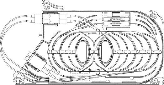
Figure 8-1 illustrates the Hub Filter module.
 |
Note The HFM is passive and does not include alarm or supervisory subunit functions. |
In an optically-protected configuration, there are two HFMs on the same ITU channel, one on the A side and another on the B side. An unprotected configuration only uses one HFM, and the HFM is located on either the A or the B side of the ONS 15252 MCU.
|
Note The front of the HFM displays the ITU grid wavelength. See Table 8-2 for the ITU channels and frequencies. |
The connectors used to add to the line and drop from the line are mounted in one MU duplex unit, and added/dropped at the lower duplex MU adapter on the HFM.
You should daisy chain the HFMs to transfer all wavelengths not yet stripped from the composite signal (drop) or to add the add signal to the outgoing composite signal. If the HFM is the last module in the daisy chain, then connect the connectors to either a Bridge module (BM), a Termination module (TM), a Connection Module X, or a Connection Module Y, depending on the configuration.
|
Note HFM connectors include four MU optical fiber connectors (mounted inside two MU-MU duplex adapters) and two protruding fiber pigtails that end in a duplex MU-connector. |
This section provides optical, environmental, and mechanical specifications for the HFM. The HFM is a passive device; therefore, electrical specifications and default thresholds to not apply.
Table 8-1 specifies general operating conditions.
Table 8-2 lists optical operating frequencies.
For optical loss information, refer to Chapter 1 of the Cisco ONS 15200 Product Description.
Table 8-3 lists environmental specifications for module operating conditions.
Table 8-3 HFM Module Environmental Specifications
| Item | Specification |
|---|---|
|
Short term operating temperature |
|
Normal operating relative humidity Short term operating relative humidity (per GR-63, NEBS level 3) |
The HFM consists of the following parts:
The module fiber diameter is 0.9 mm (0.04 in.) except for the 15 cm (6 in.) fiber protrusion (measured from the tip of the connector) which have a 2.0-mm (0.8 in.) jacket.
Table 8-4 lists HFM mechanical specifications.
This section explains how to remove and replace the HFM. The HFM is installed in the passive optical shelf of the ONS 15252 MCU. Make sure the replacement module and any supplies, such as tagging materials, are present on site before beginning the removal and replacement procedures. Figure 8-2 illustrates HFM placement in the passive optical shelf.
 |
Warning The ONS 15252 Multichannel Unit (MCU) is energized with -48 VDC power. |
 |
Caution Static electricity can damage electro-optical modules. While handling electro-optical modules, wear a grounding wrist strap to discharge the static buildup. Wrist straps are designed to prevent static electricity damage to equipment. |
|
Warning Follow proper safety procedures when removing modules without switching off the relevant subrack. |
|
Warning Do not look directly at the optical connector output beams during connector removal. The beams can cause permanent eye damage. |
Step 2 Disconnect the duplex MU connector going to and from the Network Adaptation module (NAM).
Step 3 Cap the optical fiber ends.
Step 4 Insert dust caps into the MU-MU adapter located on the HFM.
Step 5 Push the button at the bottom of the HFM front panel, then push the HFM slightly upward (about 10 mm / 0.5 in.) to expose two lateral grooves on the top.
Step 6 Remove the optical fiber from the two lateral grooves on top of the HFM.
Step 7 Disconnect the duplex MU connector that is installed in the HFM. The duplex connector is on the optical fiber jumper cable that protrudes from the adjacent HFM.
Step 8 Cap the optical fiber ends.
Step 9 Disconnect the duplex MU connector installed in the adjacent HFM. The duplex connector is on the optical fiber jumper cable that protrudes from the HFM being removed.
Step 10 Clean the disconnected optical fiber ends and install them in the HFM being removed.
Step 11 Push the button at the bottom of the HFM front panel, then push the HFM slightly upward.
Step 12 Carefully remove the HFM from the passive optical shelf.
Step 13 Remove the optical fiber caps from the adjacent HFM jumper cable.
Step 14 Clean the optical fiber connector.
Step 15 Insert the connector into the next HFM.
Step 16 Insert Dummy Filter modules in the middle of the passive optical shelf until it is filled.
Step 17 Close the passive optical shelf cover.
|
Warning Do not look directly at the optical connector output beams during connector removal. The beams can cause permanent eye damage. |
Step 2 Remove two or three DFM modules to create more work space.
Step 3 Remove the optical fiber jumper connector at the adjacent HFM (to the left on the A side or to the right on the B side).
Step 4 Cap the optical fiber ends.
Step 5 Slide in the new HFM, making sure there is interlock between the rear-mounted crossbeam in the MCU and the groove in the bottom of the HFM.
Step 6 Press at the bottom of the new HFM, applying downward pressure, and snap into place.
Step 7 Disconnect the duplex MU connector that is installed on the new HFM. The duplex connector is on the optical fiber jumper cable that protrudes from the new HFM.
Step 8 Clean the optical fiber MU duplex connector
Step 9 Connect the duplex MU connector to the adjacent HFM.
Step 10 After removing the fiber caps, clean the disconnected optical fiber ends removed in Step 3.
Step 11 Connect the duplex MU connector of step 3-10 to the HFM being installed. The duplex connector is on the optical fiber jumper cable that protrudes from the adjacent HFM.
Step 12 Remove the dust plugs from the second MU-MU adapter located on the HFM.
Step 13 Uncap the duplex MU connector of the associated NAM.
Step 14 Inspect the optical fiber connector and clean the optical fiber connector.
Step 15 Connect the duplex MU connector from the NAM to the HFM.
Step 16 Push the HFM slightly upward (about 10 mm / 0.5 inch) to expose two grooves on the top of the HFM.
Step 17 Position the optical fiber (at the correct length and bending radius) in the two lateral grooves on top of the HFM.
Step 18 Press the bottom of the HFM, applying downward pressure and snap carefully into place.
Step 19 For a protected channel, repeat steps 12-17 for the other side.
Step 20 Check that the fibers on top of the passive optical shelf are drawn in even curves without tight loops or kinks.
Step 21 Close the passive optical shelf cover.
![]()
![]()
![]()
![]()
![]()
![]()
![]()
![]()
Posted: Thu May 1 22:28:30 PDT 2003
All contents are Copyright © 1992--2002 Cisco Systems, Inc. All rights reserved.
Important Notices and Privacy Statement.