|
|

This chapter describes how to view and modify the configuration of the Client Layer Interface Port (CLIP) modules using the Maintenance Manager. Refer to the Cisco ONS 15200 Command Line Interface Manual for information about parameters shown in the Maintenance Manager.
The Clip Inventory screen provides information about the selected CLIP module. The Clip Inventory screen is divided into four areas: General, Board, RX (receive) transponder, and TX (transmit) transponder. There are no editable fields on the Module Inventory screen.
The General area of the Clip Inventory screen displays inventory information about the entire CLIP module (Figure 3-1). See Table 3-1 for general parameters.
| Parameter | Definition |
|---|---|
Clip Element Id | Displays the ID of the Client Layer Interface Port (CLIP) module. |
ITU Channel | Displays the channel where the CLIP module is configured to operate. Channels are defined according to the standard ITU grid. |
DCN Address | Defines the Data Control Network address assigned to this module. |
Clip Part No | Displays the Cisco part number for the CLIP module. |
Clip Serial No | Displays the Cisco serial number for the CLIP module. |
CLEI code | Displays the CLEI code for the selected module. |
NEC Part No | Displays the Network Element Controller part number. |
FW Revision No | Displays the revision number of the firmware. |
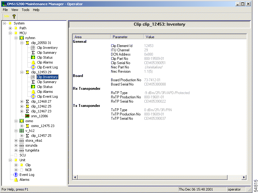
The Board area of the Clip Inventory screen displays inventory information about the main circuit board on the CLIP module (Figure 3-1). See Table 3-2 for Board parameters.
| Parameter | Definition |
|---|---|
Board Production No | Displays the part number assigned to the CLIP module main circuit board. |
Board Serial No | Displays the Cisco serial number of the CLIP module main circuit board. |
The Rx Transponder area of the Clip Inventory screen displays inventory information about the Rx transponder submodule on the CLIP module (Figure 3-1). See Table 3-3 for Rx Transponder parameters.
| Parameter | Definition |
|---|---|
RxTP Type | Displays the type of Rx transponder installed on the selected CLIP module. The Type definition is divided into these parts:
|
RxTP Production No | Displays the Cisco part number of the Rx transponder module installed on the selected CLIP module. |
RxTP Serial No | Displays the serial number of the Rx transponder module installed on the selected CLIP module. |
The Tx Transponder area of the Clip Inventory screen displays inventory information about the Tx transponder submodule on the CLIP module (Figure 3-1). See Table 3-4 for Tx Transponder parameters.
| Parameter | Definition |
|---|---|
TxTP Type | Displays the type of Tx transponder installed on the selected CLIP module. The TxTP Type definition has these parts:
|
TxTP Production No | Displays the Cisco part number of the Tx transponder module installed on the selected CLIP module. |
TxTP Revision No | Displays the revision of the Tx transponder module installed on the selected CLIP module. |
TxTP Serial No | Displays the Cisco serial number of the Tx transponder module installed on the selected CLIP module. |
The Clip Summary screen displays the configuration of the selected CLIP module (Figure 3-2). The Clip Summary screen is divided into three areas: General, DWDM Side, and Client Side.
The information available on the Summary screen varies, depending on whether the Summary screen is associated with a CLIP module configured as protected or unprotected. Figure 3-2 shows the Summary screen for a protected CLIP. The Summary screen for unprotected clip modules does not show the Switch Mode or Standby Path fields.
The following fields on the Summary screen can be edited by the operator:
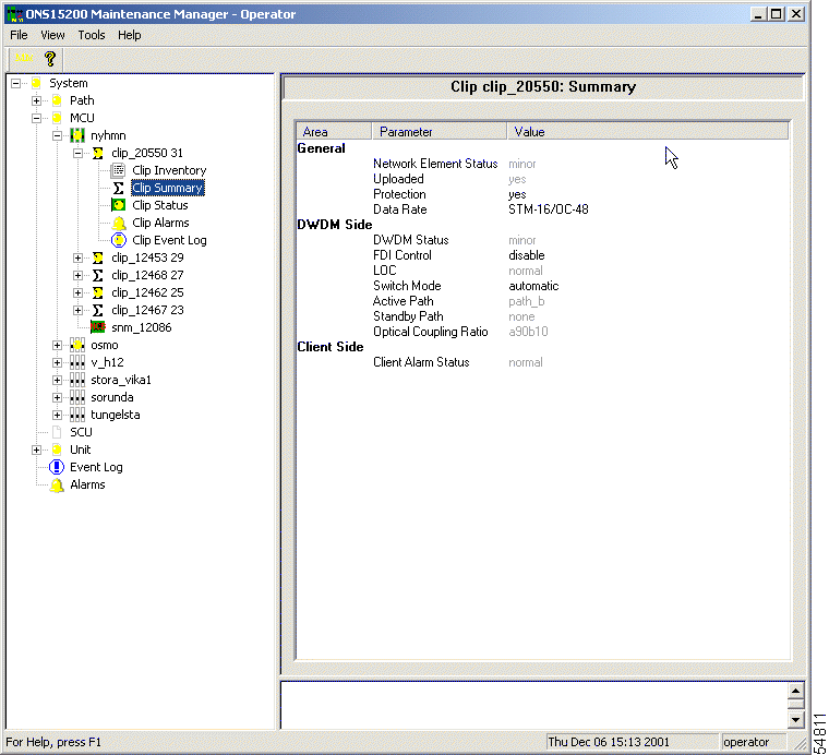
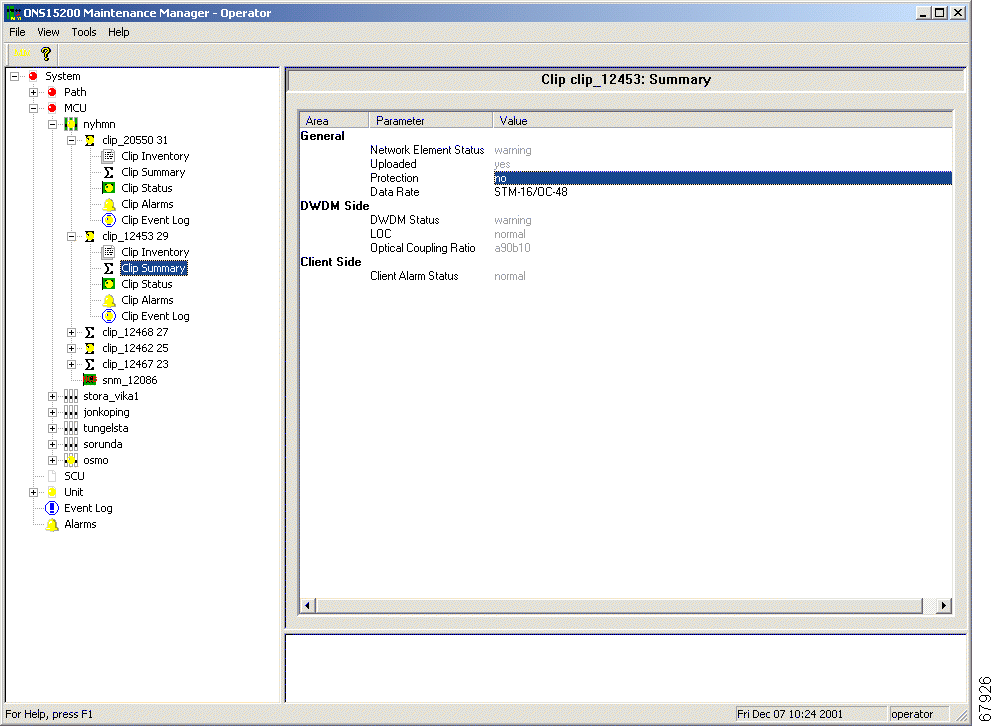
The General area of the Clip Summary screen describes general parameters that apply to the CLIP module. The values for the Protection Data Rate field can be changed by the operator. Table 3-5 describes the parameters found in the General area of the Clip Summary screen.
| Parameter | Value |
|---|---|
Network Element Status | Uninit—The Maintenance Manager did not recieve any information from the selected CLIP module. Normal—The selected CLIP module has not reported any alarms. Warning—The selected CLIP module has reported a condition that exceeds a high warning or lower warning threshold value. Minor—The selected CLIP module generated a minor alarm based on a condition that exceeds a high alarm or lower alarm threshold value. Major—The selected CLIP module generated a major alarm based on a condition that exceeds a high alarm or lower alarm threshold value. Critical—The selected CLIP module generated a critical alarm based on a condition that exceeds a high alarm or lower alarm threshold value. Installed—The NE detects the physical presence of the CLIP module, but data from the CLIP module has not been uploaded yet. Possible causes include a faulty connection or lack of management of the CLIP. Not_installed—The NE has lost contact with the CLIP module. Undefined—An alarm was received but its content cannot be interpreted. |
Protection | Yes—The selected CLIP module's traffic is protected on another circuit. No—The selected CLIP module's traffic is not protected on another circuit. |
Uploaded | Yes—When the CLIP was detected, all required data about the CLIP was successfully retrieved from the CLIP. No—When the CLIP was detected, all required data about the CLIP was not successfully retrieved from the CLIP. To move the Uploaded state from No to Yes, you can manually select Upload from the Tools/Clip menu or right-click the specified CLIP and select Upload. Note If this parameter is set to No, the Network Element Status value will be Installed. Thereby the Status will not be recognized and there will be no status information in the Explorer View (tree control). |
Data Rate | Describes the rate at which data is being transmitted in and by the ONS 15200 system. The operator can change this value. The "Changing the Data Rate" section describes the procedure for changing the data rate. |
Follow these steps to change the data rate for the selected CLIP module:
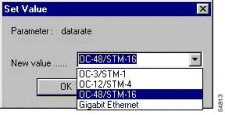
Step 2 Select the desired data rate from the list. Table 3-6 describes the data rate selections available.
Step 3 Click OK. The selected data rate appears on the Clip Summary screen. The change is effective immediately.
| Parameter | Value |
|---|---|
OC-3 | The selected CLIP module will transmit at a bit rate of 155 Mbps. |
STM-1 | The selected CLIP module will transmit at a bit rate of 155 Mbps. |
OC-12 | The selected CLIP module will transmit at a bit rate of 622 Mbps. |
STM-4 | The selected CLIP module will transmit at a bit rate of 622 Mbps. |
OC-48 | The selected CLIP module will transmit at a bit rate of 2.5 Gbps. |
STM-16 | The selected CLIP module will transmit at a bit rate of 2.5 Gbps. |
gbit_eth | The selected CLIP module will transmit data at a gigabit ethernet rate (approximately 1.25 Gbps). |
pass_through | The selected CLIP module will allow data to pass through regardless of data rate (available only for 2R/3R CLIP modules). |
The DWDM Side area of the Clip Summary screen describes parameters that apply to the ONS 15200 transmissions between CLIP modules. The values for the Switch Mode field can be changed by the operator. Table 3-7 describes the DWDM Side parameters.
| Parameter | Value | ||
|---|---|---|---|
DWDM Status |
| ||
FDI Switch | Enable—If a protected CLIP module receives a Forward Defect Indication (FDI) alarm, it will automatically switch to the standby path. Disable—If a protected CLIP module receives a FDI alarm, it will not switch to the standby path.
| ||
Switch Mode | (Displayed only if the CLIP supports fiber protection.) Displays the switching scheme assigned to the selected CLIP module. The operator can change this value. The switching scheme selected determines how the ONS 15200 system will behave if the input signal is lost on the active path. The "Procedure: Change the Switch Mode" section describes the procedure for changing the switching scheme. | ||
Active Path | Displays the primary path on which the CLIP module is receiving. In protected configurations, the active path can be either path_a or path_b. | ||
Standby Path (protected channel only) | Displays the secondary path on which the CLIP module is receiving. In the event of a disruption on the primary path, the system uses the signal received on the standby path. The standby path is always the opposite of the active path, if it exists. Note When switch mode is set to either forced_a or forced_b, there is no alternative standby signal. The system is forced to use either the a or b path. | ||
Optical Coupling Ratio | Describes how the optical power is split between the A side and the B side of the system. In a protected system the following values are available:
In an unprotected system the following values are available:
|
 |
Note Switch mode is only available on protected channels. |
Follow these steps to change the switch mode for the selected CLIP module:
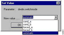
Step 2 Select the desired switch mode from the list. Table 3-8 describes the selections available.
Step 3 Click OK. The value appears on the Clip Summary screen. The changes are effective immediately.
| Parameter | Value |
|---|---|
cond_a | Automatically selects path A as the primary path if the signal on the A side is present. If the signal is lost and power is present on the B side, the path switches. However, as soon as the A-side signal returns, the signal reverts to the A side. |
cond_b | Automatically selects path B as the primary path if the signal on the B side is present. If the signal is lost and power is present on the A side, the path switches. However, as soon as the B side signal returns, the signal reverts to the B side. |
forced_a | Forces traffic to the A side. Note If the switch mode is set to forced_a, traffic cannot revert to the B side if the A side fails. |
forced_b | Forces traffic to the B side. Note If the switch mode is set to forced_b, traffic cannot revert to the A side if the B side fails. |
automatic | Automatically switches traffic to the standby path when the active path input signal is lost. The switch is non-revertive. |
The Client Side area of the Clip Summary screen describes parameters that apply to the ONS 15200 transmissions between the selected CLIP module and the client equipment. Values in this section cannot be modified by the operator. The Client Alarm Status can be set to the follow values:
The Clip Status screen displays the operating status of the CLIP module (Figure 3-6). Table 3-9 describes the parameters found in this screen.
| Parameter | Definition |
|---|---|
Area | Describes the type of information available. |
Name | Displays the name of the measurement or alarm. |
Suppress | Contains a checkbox to select or deselect the Suppress feature, which suppresses the alarm in the local database. The CLIP will still send all future alarms to all subscribers including the local database. |
Inhibit | Contains a checkbox to select or deselect the Inhibit feature, which inhibits the alarm on the CLIP. |
Status | Describes the status of the alarm. The following values are possible:
|
Low Alarm | Displays the lower threshold value that will cause an alarm to be generated. |
Low Warning | Displays the lower threshold value that will cause a warning to be generated. |
Present Value | Displays the real-time value of the parameter as measured by the module. |
High Warning | Displays the upper threshold value that will cause a warning to be generated. |
High Alarm | Displays the upper threshold value that will cause an alarm to be generated. |
Unit | Displays the unit of measure for the values of the selected parameter. |
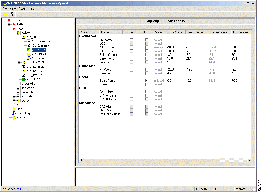
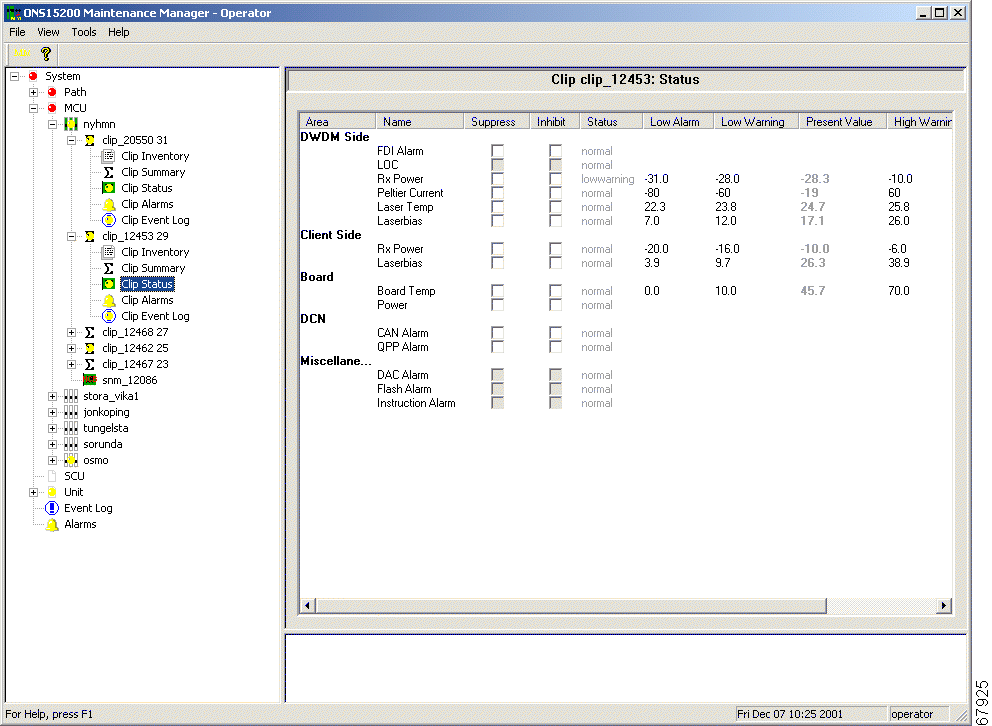
The Clip Status screen is divided into four areas: DWDM Side, Client Side, Environment, and DCN. The DWDM Side area lists the settings and current values of the signal from the DWDM side of the ONS 15200 system. Parameters listed in the Client Side area describes the quality of the signal received from the client equipment. The Environment area provides the board temperature and power of the CLIP module. The DCN area indicates any Control Area Network (CAN) or QPP alarms.
The information available on the Status screen varies, depending on whether the associated CLIP module is configured as protected or unprotected. Figure 3-6 shows the Status screen for a protected CLIP. The Status screen for unprotected CLIP modules shows only a general DWDM Rx Power field.
For each parameter, the following fields can be modified:
Follow these steps to configure alarms and warnings so they are not reported.
 |
Caution Suppressing alarms can be service affecting. |
Step 2 To configure the alarm to report, clear the checkbox.
Follow these steps to set the CLIP module threshold available on the Clip Status screen:
Step 2 Type the desired value.
Step 3 Click OK. The new threshold value takes effect immediately.
The DWDM Side area of the Clip Status screen describes how the CLIP module is operating in relation to the MCU and SCUs that make up the ONS 15200 network (Figure 3-6). Values for A RX Power, B RX Power, Peltier Current, Laser Temperature, and Laser Bias are listed in this section. Table 3-10 describes the optical network parameters. All parameters except FDI Alarm and LOC can be suppressed/inhibited.
| Parameter | Definition |
|---|---|
FDI Alarm | Displays whether the CLIP module received a Forward Defect Indication (FDI) alarm. |
LOC | Displays whether the CLIP module received a Loss of Channel (LOC) alarm. |
A RX Power | Displays the values associated with the strength of the signal received from the A-side MCU or SCU. |
B RX Power | Displays the values associated with the strength of the signal received from the B-side MCU or SCU. |
RX Power | Displays the values associated with the strength of the received signal. |
Peltier Current | Displays the values associated with the strength of the current to the Peltier device. The Peltier device regulates the temperature of the laser and maintains the wavelength of the transmitted signal. |
Laser Temp | Displays the values associated with the temperature of the laser that transmits to the SCUs and MCU in the ONS 15200 network. |
Laserbias | Displays the laser bias current for the selected CLIP module. |
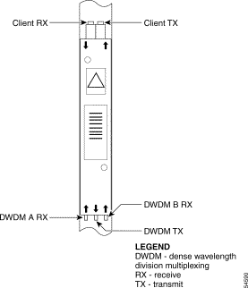
Figure 3-8 shows the RX and TX power measurement points for the optical network interfaces on a CLIP module.
The Client Side area of the Clip Status screen describes how the CLIP module is operating in relation to the client equipment attached to the ONS 15200 system. Values for Client RX Power and Laser Bias are listed on this screen. Table 3-11 describes the client access parameters.
| Parameter | Definition |
|---|---|
RX Power | Displays the strength of the signal received from the client equipment attached to the ONS 15200 network. |
Laserbias | Displays the laser bias current for the selected CLIP module. |
The Board area of the Clip Status screen provides the Board Temperature and Power parameters for the CLIP module. Table 3-12 describes the Board parameters.
| Parameter | Definition |
|---|---|
Board Temperature | Displays the values associated with the ambient temperature on the surface of the CLIP module. |
Power | Displays the status of the input power coming into the SCU or MCU from the AC to DC converter. |
The DCN area of the Clip Status screen provides the CAN bus and QPP signal status. Table 3-13 describes the DCN parameters.
| Parameter | Definition |
|---|---|
CAN alarm | Displays the status of the CAN bus. |
QPP A alarm | Displays the transmission status of the internal datacom link on the A side of the network. |
QPP B alarm | Displays the transmission status of the internal datacom link on the B side of the network. |
QPP alarm | Displays the transmission status of the internal datacom link of the network. |
The Miscellaneous area of the Clip Status screen provides miscellaneous hardware and software alarm information status. Table 3-13 describes the DCN parameters.
| Parameter | Definition |
|---|---|
DAC alarm | A hardware fault relating to the digital/analog converter (DAC) has occurred. |
Flash alarm | A hardware fault relating to the eeprom has occurred. |
Instruction alarm | An entity is trying to write to an unavailable position. |
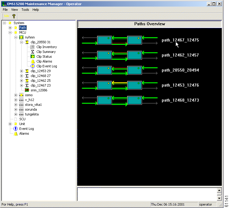
The Path Folder Overview screen provides a graphical representation of the optical paths configured for the ONS 15200 network (Figure 3-9). LEDs indicate active alarms on the NE. The signal direction is indicated by the lines entering or exiting the NE. Green lines indicate inbound signals and white lines indicate outbound signals. A red line indicates inbound signals that have alarms somewhere on the path.
![]()
![]()
![]()
![]()
![]()
![]()
![]()
![]()
Posted: Mon Jan 7 02:02:40 PST 2002
All contents are Copyright © 1992--2002 Cisco Systems, Inc. All rights reserved.
Important Notices and Privacy Statement.