|
|

This chapter provides a general overview of the Maintenance Manager software. See "CLIP Module Configuration" for detailed information regarding specific Maintenance Manager screens.
This list describes the features of the Maintenance Manager software:
The Maintenance Manager screen (Figure 2-1) is divided into the following three sections:
To navigate to different screens, click the folder or page icons in the navigation area. Clicking a folder expands it to display the pages and subfolders it contains. Clicking a page displays the relevant system information.
 |
Note The Communication Interface Module (CIM) that the Maintenance Manager is connected to determines which CLIP modules are visible. You can view CLIP modules in the shelf where the CIM resides, as well as the mates of those CLIP modules. |
The System folder contains the following subfolders:
The System folder also contains the system-level Active Alarms screen and the system-level Event Log screen.
 |
Note The system-level Event Log screen is an aggregate of all Client Layer Interface Port (CLIP) module event logs. The system-level Active Alarms screen contains all CLIP module alarms plus all system-level alarms. |
Clicking the Path folder provides a graphical view of any CLIP module circuit paths (Figure 2-2). Icons represent the active path, standby path, network elements, and alarms.
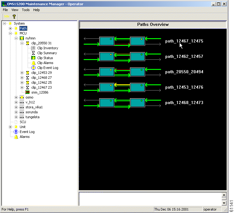
Opening this folder displays folders for these paths, and from these subfolders you can access information about the CLIP modules on those paths. See the "CLIP Folders" section for details on the information available for CLIP modules.
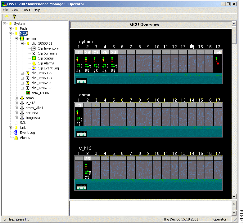
Clicking the MCU folder displays a graphical view of the MCU (Figure 2-3). Each MCU folder provides an inventory of the CLIP modules in that MCU, and from these subfolders you can access information about the CLIP modules. See the "CLIP Folders" section for details on the information available for CLIP modules.
 |
Note The specific MCUs available depend on the CIM to which the Maintenance Manager is connected. |
The SCU folder provides access to each of the visible SCUs in the Maintenance Manager. CLIP modules located in the selected SCU are accessible in a separate subfolder.
The Unit folder provides access to the CLIP modules and Subnetwork Managers (SNMs) installed in the ONS 15200 network that are visible from the Maintenance Manager. Modules listed in the Unit folder are sorted by unit name rather than their location.
The CLIP folders provide access to each CLIP module installed in the system. There are several ways to access the CLIP folder, but each provides the same categories of information. CLIP folders are located in the following folders:
The CLIP folder is identified by the serial number of the CLIP module and the ITU channel where it is assigned (default) or any name assigned to that CLIP module by a operator user through the Command Line Interface. Refer to the Cisco ONS 15200 Command Line Interface Manual for information on assigning a name to a CLIP module.
Each CLIP folder contains the following screens:
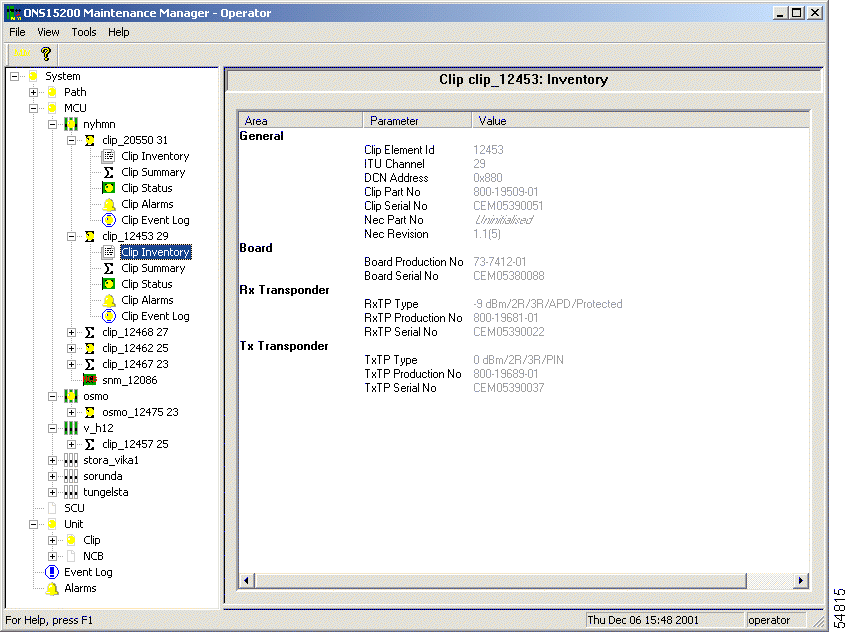
The Clip Inventory screen gives general system information, as well as information regarding the board, receive transponder, and transmit transponder (Figure 2-4).
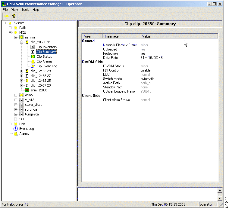
The information available on the Clip Summary screen varies depending on whether the Clip Summary screen is associated with a CLIP module that is configured as protected or unprotected.
The following information is provided by the Clip Summary screen:
For more information regarding each parameter and whether you can configure it from Maintenance Manager, see "CLIP Module Configuration."
Figure 2-5 shows the Clip Summary screen for a protected CLIP module.

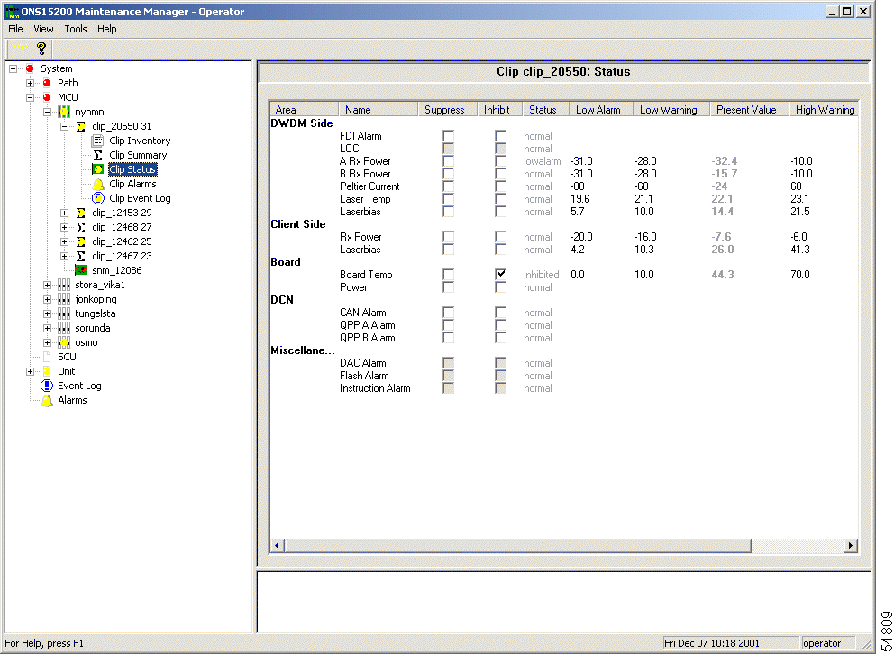
The information available on the Clip Status screen varies depending on whether the Clip Status screen is associated with a CLIP module that is configured as protected or unprotected.
The Clip Status screen provides the following information:
For more information regarding each parameter, see to "CLIP Module Configuration."
Figure 2-6 shows the Clip Status screen for a protected CLIP.
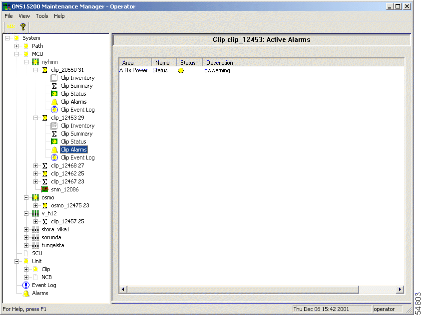
The Clip Alarms screen provides a list of all active alarms involving that CLIP module (Figure 2-7). A system alarm screen is also available for the complete ONS 15200 system. For more information regarding each parameter, see "Alarms." For more information regarding individual alarms, refer to the Cisco ONS 15200 Product Description.
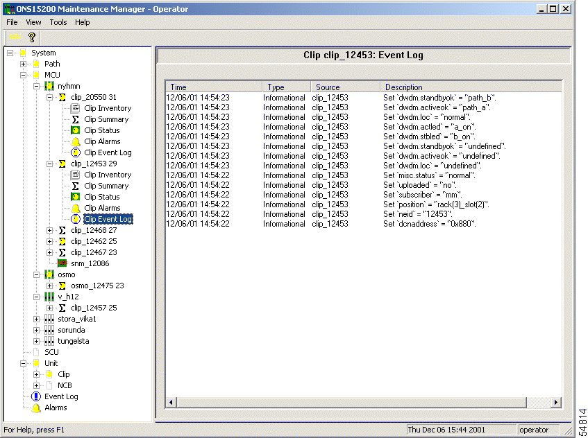
The Clip Event Log screen provides a tabular list of system events (Figure 2-8). The following information is provided:
![]()
![]()
![]()
![]()
![]()
![]()
![]()
![]()
Posted: Mon Jan 7 02:01:08 PST 2002
All contents are Copyright © 1992--2002 Cisco Systems, Inc. All rights reserved.
Important Notices and Privacy Statement.