|
|

This chapter describes the Cisco ONS 15200 mechanical components. It also provides electrical, electromagnetic, and safety information about the ONS 15200.
Equipment in the ONS 15200 system is modular in design. Each system function is carried out by modules located in either an ONS 15252 MCU or an ONS 15201 SCU. Sites in the ONS 15200 system consist of either an ONS 15252 MCU, an ONS 15201 SCU, or a combination of the two. ONS 15200 site configurations may also include a power distribution panel (PDP).
The ONS 15216 equipment is not described in this manual. For further information please see the ONS 15216 manuals.
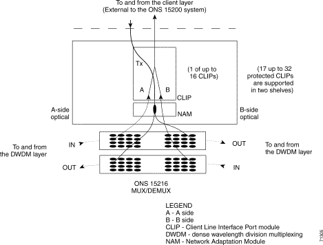
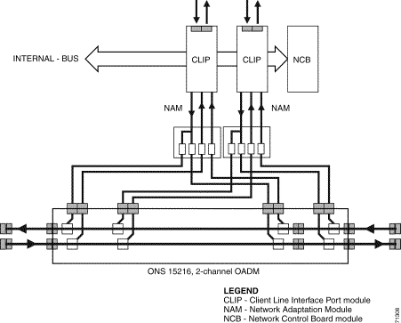
The ONS 15252 MCU communicates with the other nodes in the ONS 15200 system on one or several channels. Each channel occupies a wavelength, and some ONS 15200 system configurations reuse a wavelength. As shown in Figure 3-1, several channels of information, each occupying a wavelength, enter the node from the DWDM layer. Each channel can enter the ONS 15252 MCU from the A side, the B side, or the A side and B side.
The ONS 15252 MCU communicates with the other nodes in the ONS 15200 system on one or more wavelengths. Information originates at the ONS 15252 MCU CLIP module. For optically protected channels, the Network Adaptation module (NAM) splits the information and transmits it in opposite directions through two ONS 15216 MUX/DEMUX unit in specific wavelength.
For unprotected channels, the NAM transmits the information through one ONS 15216 MUX/DEMUX unit in a specific wavelength.
For Hardware Release 2.0 (applications with external DWDM filters), the shelves include a baffle and extra space for the new NAM modules. The baffle is a partially perforated, angled metal plate that is mounted below and behind the metal support beam and is mechanically attached to the back of the shelf. It runs the width of the shelf. To view the baffle, look up through the ventilation cavities at the back of the shelf.
ONS 15252 Releases 2.0 include a fan unit. Before using the Release 2.0 shelf, you must install the fan unit. See the "Fan Unit" section for more information about the fan unit.
 |
Caution You must install the fan unit in a shelf for ONS 15200 Release 1.0.1 and later. Running the Release 1.0.1 shelf or later shelf without the fan unit will result in a unit that is not compliant to any specifications, nor is warranted or supported by Cisco. In addition, such usage may result in equipment damage. |
 |
Caution Do not install the fan unit in a Release 1.0 shelf. Running the Release 1.0 shelf with a fan unit will result in a unit that is not compliant to any specifications, nor is warranted or supported by Cisco. In addition, such usage may result in equipment damage. |
ONS 15200 Release 2.0 (application with external DWDM filters) includes an updated NAM module. The Release 2.0 NAM has two or four optical connectors below the faceplate. The ONS 15200 Release 2.0 (application with external DWDM filters) requires the Release 2.0 NAM. See the Cisco ONS 15200 Module Handbook R2.0 for more information about the NAM.
The ONS 15201 SCU communicates with the other nodes in the ONS 15200 system on a specific wavelength or channel. The SCU uses a single CLIP module. From the DWDM layer, several channels of information, each occupying a wavelength, enter the ONS 15201 SCU. Each DWDM channel of information can enter the ONS 15201 SCU from the A side, the B side, or the A side and B side.
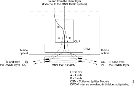
The Collector Splitter module (CSM) drops and transfers the specific channel or wavelength intended for the ONS 15201 SCU to the CLIP module. For protected channels, the CSM drops the channel from the A side and B side. For unprotected channels, the CSM drops the channel from either the A side or B side.
The CLIP transfers information originating at the ONS 15201 to the CSM for protected channels. The CSM splits the information and transmits it at a specific wavelength or channel in opposite directions on the A side and B side. The CSM does not split unprotected channels; it transmits them directly to either the A side or B side. Information carried on a wavelength or channel intended for another ONS 15200 node passes through the ONS 15216 OADM without interference except for the insertion loss caused by the ONS 15216 OADM. Figure 3-2 shows a functional representation of an ONS 15201 SCU.
ONS 15200 site configurations can include a power distribution panel (PDP). The PDP distributes power to the ONS 15200 site and provides power redundancy. It uses input and output fusing to provide system protection.
All Release 1.0.1 (or later) ONS 15252 MCU site configurations require a fan unit mounted above the ONS 15252 MCU in the equipment rack. Release 1.0.1 (or later) MCU are NEBS 3 complaint. ONS 15200 Release 2.0 CLIPs require a NEBS 3 equipment rack. The fan unit contains eight small fans that run simultaneously at constant speed. The fans push air down through the MCU to cool the CLIP modules. The fan unit is powered by its own dual -48 VDC power inlets independently of the MCU. If the fan unit fails, it generates an alarm to indicate multi- or single-fan failure. Located on the front panel of the fan unit are three LEDs to indicate alarm status. Table 3-1 lists the LED status and cause of alarm.
| LED | Status | Cause |
|---|---|---|
Red | Major alarm | Multi-fan failure |
Yellow | Minor alarm | Single-fan failure and/or single 48 VDC failure |
Green | Normal | Power on |
 |
Caution You must install the fan unit in a Release 1.0.1 shelf. Running the Release 1.0.1 shelf without the fan unit will result in a unit that is not compliant to any specifications, nor is warranted or supported by Cisco. In addition, such usage may result in equipment damage. |
 |
Caution Do not install the fan unit in a Release 1.0 shelf. Running the Release 1.0 shelf with a fan unit will result in a unit that is not compliant to any specifications, nor is warranted or supported by Cisco. In addition, such usage may result in equipment damage. |
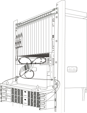
The fiber organizer distributes the client fiber-optic cables to the ONS 15252 MCU CLIP modules. Additionally, the fiber organizer provides tension relief for the client fiber-optic cables. You can also install a fiber organizer between additional ONS 15252 MCUs or ONS 15201 SCUs located at a site. A fiber organizer is always included with an ONS 15252 MCU.
You can place the fiber organizer on the fan unit front. This placement does not interfere with fan unit filter replacement. Figure 3-3 shows the fiber routing in the ONS 152252 MCU and ONS 15216 MUX/DEMUX.
This section describes the physical configuration of the ONS 15252 MCU and ONS 15201 SCU.
The ONS 15252 MCU physical configuration consists of a Network Control Board (NCB) module, Network Adaptation modules (NAMs), a Communication Interface module (CIM) and Client Layer Interface Port (CLIP) modules. (See Figure 3-4.)
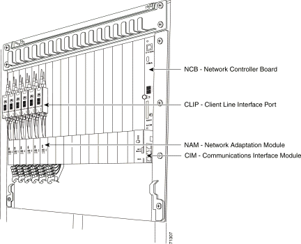
The lower portion of the ONS 15252 MCU is referred to as the passive optical shelf. The passive optical shelf has an A side and B side. The A side of the ONS 15252 MCU is located on the left side of the passive optical shelf, as seen from the front. The B side of the ONS 15252 MCU is located on the right side of the passive optical shelf, as seen from the front. Figure 3-5 shows the typical arrangement of the modules.
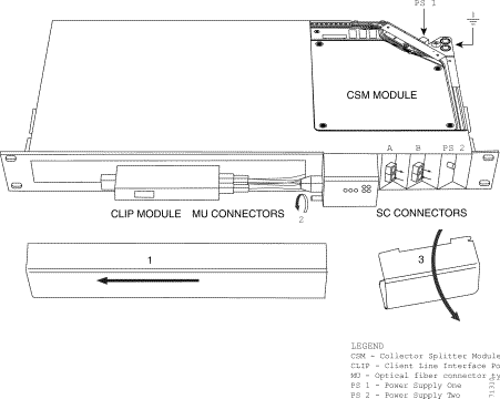
The ONS 15201 SCU physical configuration consists of a CLIP module and a CSM (Figure 3-6). The A side of the ONS 15201 SCU contains the two far-left optical line connectors on the front or back of the ONS 15201 SCU. The B side of the ONS 15201 SCU contains the two far-right optical line connectors on the front or back of the ONS 15201 SCU. The ONS 15201 SCU is normally delivered with optical connections on the front (SC type). Back placement is optional for SC connectors.
 |
Note You can order the ONS 15201 SCU with optical connectors located on either the front or the back of the unit, but not on both the front and back. |
This section describes power and grounding for the ONS 15200 system. The grounding connections for the ONS 15201 SCU and the ONS 15252 MCU are shown in Figure 3-7.
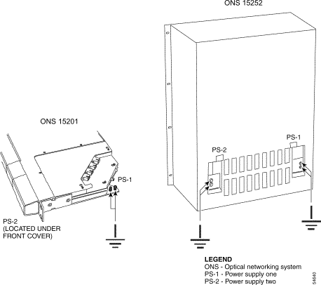
Two power supply connectors are located on the backplane of the ONS 15252 MCU. The far-right power connector (as viewed from the rear of the ONS 15252 MCU) is called PS-1 (power supply one), and the far-left power connector is called PS-2 (power supply two), as shown in Figure 3-7. The equivalent PS-1 and PS-2 power supply connector terminals are designated 0V and -48V. Grounding for the ONS 15252 MCU chassis is provided by two lug-type grounding connectors (Figure 3-7).
 |
Note To prevent ground loops, use only one grounding connector. |
The fan unit back panel has two power supply connectors. The far-right power connector (as viewed from the rear of the fan unit) is the primary source, and the far-left power connector is the secondary source. These power connectors are designated as 0V and -48V. A pair of grounding pins (M4 screws) is located next to each of the power connectors on the fan-unit back panel.
The ONS 15201 SCU chassis has two power supply connectors. The power supply located on the front of the ONS 15201 SCU chassis is labeled PS-2 (power supply two), and the power supply connector located on the backplane of the ONS 15201 SCU chassis is labeled PS-1 (power supply one) (Figure 3-6). Lug-type grounding connectors located on the back of the chassis provide grounding. The power supplies convert AC to DC and provide a regulated -48 VDC to the ONS 15201 SCU.
The ONS 15252 MCU is compliant with Network Element Building Systems (NEBS) Level 3 of Telcordia SR-3580 and applicable sections of Telcordia GR-63-CORE and Telcordia GR-1089-CORE. Additionally, the ONS 15200 system is compliant with ETS 300 019-1-1 (class 1.1), ETS 300 019-1-2 (class 2.3), and ETS 300 019-1-3 (class 3.1) for environmental requirements.
The ONS SCU 15201 is compliant with Network Element Building Systems (NEBS) Level 2 of Telcordia SR-3580 and applicable sections of Telcordia GR-63-CORE and Telcordia GR-1089-CORE. Additionally, the ONS 15200 system is compliant with ETS 300 019-1-1 (class 1.1), ETS 300 019-1-2 (class 2.3), and ETS 300 019-1-3 (class 3.1) for environmental requirements.
The ONS 15200 system is compliant with Telcordia GR-1089-CORE and FCC Part 15 specifications for electromagnetic compatibility for NEBS Level 2 (SCU) and Level 3 (MCU). Additionally, the ONS 15200 system is compliant with ETS 300 386-1, classes 1 and 2 for electromagnetic compatibility.
This section provides ONS 15200 system laser and product safety specifications.
The ONS 15200 system is compliant with IEC-60825-1, IEC 60825-2, and CFR 1040.10 requirements for laser safety.
The ONS 15200 system equipment complies with the product safety requirements in European Norm (EN) 60 950 and Underwriters Laboratory (UL) 1950. The equipment also adheres to the European Union (EU) low voltage directive LVD 73/23/ECC.
![]()
![]()
![]()
![]()
![]()
![]()
![]()
![]()
Posted: Mon Sep 30 23:14:38 PDT 2002
All contents are Copyright © 1992--2002 Cisco Systems, Inc. All rights reserved.
Important Notices and Privacy Statement.