|
|

This chapter describes common Cisco ONS 15200 network configurations. All modules mentioned in this chapter are described in more detail in "Module Descriptions."
The ONS 15200 operates in several network configuration arrangements. All ONS 15200 configurations consists of an ONS 15216 system with MUX/DEMUX and OADM, and one or more ONS 15252 Multichannel Units (MCU) or ONS 15201 Single-channel Units (SCUs). The following information describes some standard ONS 15200 network configurations, and network configurations with the ONS 15216 system, ONS 15454 (SONET) and ONS 15454 SDH system.
A configuration between ONS 15252, ONS 15201, and ONS15216 must be chosen if a dditional traffic that to be transported over the same fiber. Applications associated with the ONS 15252 MCU and the ONS 15201 SCU can be connected directly to the ONS 15216 system. The systems are connectrd by CLIPs, which function in the 100 GHz or 200 GHz ITU grid.
 |
Note The external ONS 15216 filters also function in the 100 GHz or 200 GHz ITU grid. |
This configuration allows customers with currently installed ONS 15454 networks to deploy wavelength services on the same fiber.
It is possible to connect, with SC connector(s), a protected or unprotected ONS 15201 with and without add/drop functionality towards an ONS 15216.
The ONS 15216 family contains the ONS 15216 OADM 1-channel unit, 2-channel unit, and 4-channel unit. These units provide ITU wavelength filtering for sites along an optical DWDM ring. The ONS 15216 MUX/DEMUX optically multiplexes and demultiplexes signals for use at hub or terminal sites.
The Cisco ONS 15216 Erbium-Doped Fiber Amplifer (EDFA) and the ONS 15501 EDFA are bit-rate independent optical amplifiers, which are used in gain-controlled mode. The ONS 15216 EDFA uses an input variable optical attenuator (VOA) to adjust the gain from 13 to 22 dB, whereas the ONS 15501 EDFA uses an output VOA to adjust the gain from 7 to 17 dB. Both are optimized for a range of input powers and can be used as pre-amplifiers, line amplifiers, or boosters. The units provide excellent spectral gain flatness. The optical amplifiers are physically design to fit into a 19-inch, 23-inch, or ETSI equipment rack with front, middle, or rear mounting capability. They are equipped with connectors for optional monitoring either locally or remotely.
The following configurations are possible:
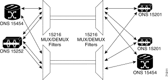
In the ONS 15200 multichannel, point-to-point configuration, multiple wavelength channels exist between two ONS 15216 MUX/DEMUX units (or in case of protection 2 MUX/DEMUX inits at each end). The MUX/DEMUX units are fed from a group ONS 15252 MCUs and/or ONS 15201 SCUs. It is possible to set up the multichannel point-to-point configuration with or without optical-layer protection. Configuring optical-layer protection requires dual fiber routes.
In the ONS 15200 multichannel, point-to-point configuration, dual fiber send information along two separate fiber routes. The dual physical route configuration supports SONET or SDH ADM protection and client-layer 1+1 APS protection.
Figure 2-1 illustrates the ONS 15200 multichannel, point-to-point configuration.
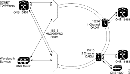
In the ONS 15200 ring configuration, wavelength channels exist between an ONS 15252 MCU and one or several ONS 15201 SCUs through an ONS 15216 MUX/DEMUX. A CLIP module installed in the ONS 15252 MCU exchanges data with an associated CLIP module installed in an ONS 15201 SCU. An ONS 15252 MCU can be connected directly to an ONS 15216 MUX/DEMUX with SC connectors. The ONS 15201 can be placed in an rack unit and driven into the 15216 OADM over SC connectors.
It is possible to install the ring configuration with or without fiber-optic protection. The ring configuration supports SONET or SDH ring protection and 1+1 APS client-layer protection. It is also possible, to arrange the ring configuration to use layer-3 load sharing. Figure 2-2 illustrates the multiservice ring configuration.
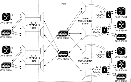
If a network combination is installed with ONS 15252 and ONS 15454, you can use the ONS 15252 to manage multiple CLIPs, each of which could face a different ring. In the ONS 15252 rings, several ONS 15216 OADM can be used to get access from an ONS 15201, ONS 15252, or ONS 15454 to the network.
In this case the installed ONS 15252 is used as a hub. Figure 2-3 illustrates the ring configuration.
In the ONS 15200 ring configurations, dual fibers send information along two separate fiber routes. The dual physical route configuration supports SONET or SDH ADM protection and client-layer 1+1 APS protection.
Release 1.1 and later of the CLIP provide the Forward Defect Indication (FDI) switch (fdi_switch), which can be enabled or disabled. The FDI function forwards the loss of client input signal (LOS) indication over which can Qeyton proprietary protocol (QPP) on the optical channel to the remote side, where the client laser will be turned off. Client LOS is indicated when the measured client input power is in the low alarm state. The indicator is assigned to a one-bit field in every QPP message, including the idle message. The severity of the FDI alarm is minor.
There are two parameter settings associated with the FDI function:
The FDI switch can be set to disabled (default) or enabled. The FDI alarm can be set to normal (causes software to display the alarm; default), inhibited, or suppressed. The CLIP FDI parametr settings can be changed using the command-line interface (CLI), web browser interface, or Maintenance Manager (MM) application.
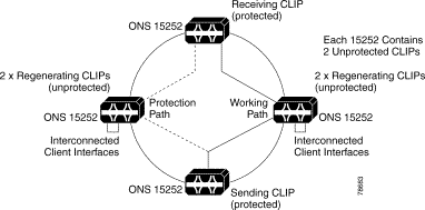
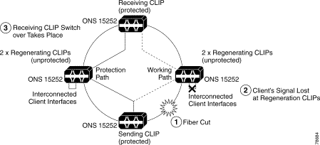
In this example, the ring circumference is so large that the dispersion limit has been reached, so regeneration of the channel is required. You do this by using two unprotected CLIPs in each regenerator site with their client interfaces connected back-to-back.
 |
Note Only Cisco ONS 15252 units are illustrated because, for management purposes, you must locate an NCB at each node; therefore, you cannot use Cisco ONS 15201 units. |
In the event of a fiber cut (Figure 2-5), no client signal will be present at the working path regenerating CLIPs. The FDI signal will inform the receiving CLIP that the client input has been lost. If FDI switching has been activated, then the receiving CLIP will switch to its protection path.
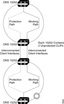
In this example, the rings are cascaded so the client traffic must be passed between the two central Cisco ONS 15252 units. You do this by interconnecting the two pairs of unprotected CLIP client interfaces in a back-to-back manner.
In the event of the fiber cut in the lower ring (as shown in Figure 2-6), the client signal between the two interconnecting working path CLIPs will be lost. The FDI signal will then inform the receiving CLIP that the client signal has been lost and if FDI switching has been activated, switchover of the receiving CLIP in the upper ring will take place.
![]()
![]()
![]()
![]()
![]()
![]()
![]()
![]()
Posted: Mon Sep 30 23:14:27 PDT 2002
All contents are Copyright © 1992--2002 Cisco Systems, Inc. All rights reserved.
Important Notices and Privacy Statement.