|
|

This chapter describes the operation of the network element management interface (NEMI), and includes the following sections:
The NEMI can be accessed through the network in three ways:
You can monitor the state of the connected chassis of the Cisco Metro 1500 series system most effectively with SNMP. With a small amount of network traffic, you can read the complete state of the chassis. Events are reported immediately to a management station.
To configure the system or to see a detailed view of a component, you can use Telnet or HyperTerminal with a LapLink cable. After logging in to the NEMI, you can process commands to read or to configure values.
Use FTP for file transfer between the NEMI and your management station. For example, use FTP to load the Management Information Base (MIB) file from the NEMI to your management station or when doing software updates on the NEMI.
SNMP defines three ways for a network management system to communicate to a network element:
Events are reported by the network element with an SNMP trap.
Variables are located in a tree-like structure and are coded with Abstract Syntax Notation One (ASN.1). The variable 1.3.6.2.1.1.1.0 is the system description, which is defined in RFC 1213.
To make the SNMP values human readable, a MIB file containing names for the variables is supplied. RFC 1213 contains a MIB file for some standard variables. Using RFC 1213, the variable 1.3.6.2.1.1.1.0 is iso.org.dod.internet.mgmt.mib-2.system.sysDescr.0.
Vendors of network elements that use nonstandard variables must supply customers with their private MIB file. The Cisco Metro 1500 series MIB file is posted at ftp://ftp.cisco.com/pub/mibs.
The Cisco Metro 1500 series system can be managed by any network management program that supports SNMP.
The NEMI supports the variables defined in RFC 1213. The most frequently used variables in system tree 1.3.6.2.1 are as follows:
The sysName and sysContact variables can be changed either with the snmpconfig command or with SNMP set instructions.
In RFC 1213 there are many variables defined for interface statistics and routing tables. For detailed information about these variables, refer to RFC 1213 documentation.
In addition to the standard variables, the Cisco Metro 1500 series system supports specific variables. The MIB tree has the following information on the housing management system and information common to all installed slots:
The MIB tree contains static configuration information as well as current status information. SNMP alarms are described in the "Trap" branch of the MIB tree.
Figure 4-1 shows the complete MIB tree beginning from root.
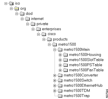
Using the SNMP manager, you can read the status values of the unit. The community string used to read the values is public. If you need to set values, use the community string private. Be careful with these community strings, because every SNMP manager in the network can change the state of the system (by changing status values) when using the private community string. (You can change the community strings using the snmpconfig command.) The following sections describe the SNMP variables.
In a large system the chassis are designated as the primary chassis with extension chassis A through G. Generally, the primary chassis and extension chassis A through C are installed in the first rack and extension chassis D through G are installed in the second rack. Each system or network element consists of up to eight chassis.
Each chassis is allotted ten slot numbers, and the first slot in each chassis is numbered 1, 11, 21, 31, 41, 51, 61, and 71 over these eight chassis. Double-width TDM4E modules occupy even slot numbers only. The modules are referenced by the slot numbers of the slots in which they are installed. The slot numbering is therefore essential for the identification of the module and for tracing a trap notification back to the module from which it originated.
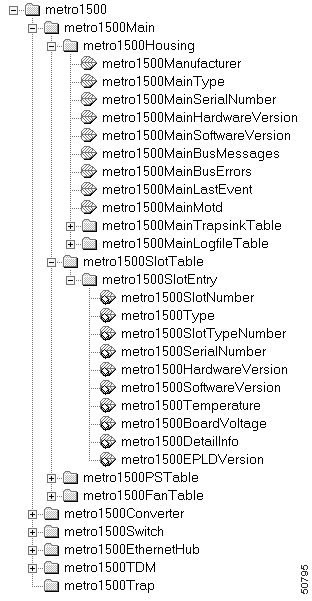
The Housing subtree, which is located under the Main heading (see Figure 4-2), describes information on the main system and the internal bus system. Table 4-1 describes the variables.
| Subtree | Variable | Type | Description |
|---|---|---|---|
metro1500 | metro1500Manufacturer | String | Manufacturer. |
| metro1500MainType | String | Type of system. |
metro1500MainSerialNumber | String | Serial number. | |
metro1500MainHardwareVersion | String | Hardware version number. | |
metro1500MainSoftwareVersion | String | Software version number. | |
metro1500MainBusMessages | Integer | Number of received messages on the internal bus. This should be a large integer value. | |
metro1500MainBusErrors | Integer | Number of transmission errors on the internal bus. This should be a small integer value. | |
metro1500MainLastEvent | Integer | Number of the last event. It is cleared when a new event occurs or 10 minutes after the last event. Use this value for periodically polling. | |
metro1500MainMotd | String | Message of the day contains information on the installed software version. | |
metro1500MainTrapsinkTable | Table | Table of trap sinks. | |
metro1500MainLogFileTable | Table | Table of log files. |
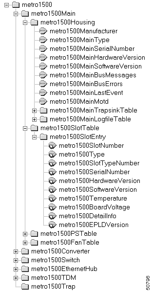
The SlotTable subtree, which is located under the SlotEntry heading (see Figure 4-3), describes general information for the module installed in that slot. This information includes the type of module, its version number, and its environmental state. Table 4-2 describes the variables and Table 4-3 describes the slot type numbers.
| Subtree | Variable | Type | Description |
|---|---|---|---|
metro1500 | metro1500SlotNumber | Integer | Number of the installed module |
metro1500Type | String | Type of the installed module | |
metro1500SlotTypeNumber | Integer | Slot type number1 | |
metro1500SerialNumber | Integer | Serial number | |
metro1500HardwareVersion | String | Hardware version | |
metro1500SoftwareVersion | String | Software version | |
metro1500Temperature | Integer | Environmental temperature of the module in degrees Fahrenheit/Celsius | |
metro1500BoardVoltage | Integer | Supply voltage on the device in millivolts | |
metro1500DetailInfo | Object Identifier | Link to a table where special information on this device type is available | |
metro1500EPLDVersion | Integer | Software version of the programmable gate array |
| 1See Table 4-3 for slot type numbers. |
| Slot Type Number | Slot Type |
|---|---|
0 | hotStandbyConverter |
1 | metro1500_Converter |
5 | metro1500_2_5GbitConverter |
7 | metro1500_TRL_Converter |
10 | metro1500_4PortTDMCard |
32 | nemi |
33 | demi |
39 | metro1500_EthernetHubCard |
64 | switch |
255 | other |
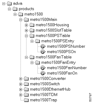
The PSEntry subtree, which is located under the PSTable heading, describes status information for the power supplies installed in the system. The FanEntry subtree, which is located under the FanTable heading, describes status information for the fan assemblies installed in the system.
The PSEntry and FanEntry subtrees (see Figure 4-4) have two variables: one is the part number and the other is the on/off status. Table 4-4 and Table 4-5 describe these variables.
There are two main power supplies and two fan power supplies in each chassis. The status of each power supply and fan power supply is monitored. These states are sequentially numbered, first the two main power supplies and then the two fan power supplies: thus "1, 2" refer to the main power supplies 1 and 2, and "3, 4" refer to power supplies for the two fans. These power supplies are further sequentially numbered over the whole multi-chassis system, ordered by chassis ID. See Table 4-6.
The pair of fans in each chassis is numbered 1 and 2 and are further sequentially numbered over the whole multi-chassis system, ordered by chassis ID. See Table 4-7. Facing the chassis, fans with odd numbers are located on the left side and fans with even numbers are located on the right side.
| Subtree | Variable | Type | Description |
|---|---|---|---|
metro1500 | metro1500PS | Integer | Main power supply number1 Fan power supply number2 |
metro1500PSOn | Integer | Power supply status: |
| 1See Table 4-6 for main power supply numbers. 2See Table 4-7 for fan power supply numbers. |
| Subtree | Variable | Type | Description |
|---|---|---|---|
metro1500 | metro1500FanNumber | Integer | Fan number1 |
metro1500FanOn | Integer | Fan status: |
| 1See Table 4-7 for fan numbers. |
| Main Power Supply Number | Fan Power Supply Number | Location |
|---|---|---|
1, 2 | 3, 4 | Primary chassis |
5, 6 | 7, 8 | Extension chassis A |
9, 10 | 11, 12 | Extension chassis B |
13, 14 | 15, 16 | Extension chassis C |
17, 18 | 19, 20 | Extension chassis D |
21, 22 | 23, 24 | Extension chassis E |
25, 26 | 27, 28 | Extension chassis F |
29, 30 | 31, 32 | Extension chassis G |
| Fan Number | Location |
|---|---|
1, 2 | Primary chassis |
3, 4 | Extension chassis A |
5, 6 | Extension chassis B |
7, 8 | Extension chassis C |
9, 10 | Extension chassis D |
11, 12 | Extension chassis E |
13, 14 | Extension chassis F |
15, 16 | Extension chassis G |
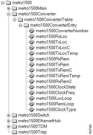
The ConverterEntry subtree, which is located under the ConverterTable heading, describes information for the converter card installed in the slot. See Figure 4-5.
The ConverterEntry subtree describes status information for the converter card's communication channels on the remote and local side, and on the receiving and transmitting (or transceiving) modules that maintain these communication channels. See Table 4-9.
The type of clock is specified by a code number. Table 4-10 provides a list of all currently installable clock types with their clock type numbers.
| Subtree | Variable | Type | Description |
|---|---|---|---|
metro1500 Converter Entry | metro1500Converter Number | Integer | Slot number of installed converter card. |
metro1500RxLoc | Integer | Status of the local receiver: | |
metro1500TxLoc | Integer | Status of the local transmitter: | |
metro1500 Converter Entry | metro1500TxLocC | Integer | Current of the local transmitter in milliamperes. This value is only available if a current sensor is installed. |
metro1500TxLocTemp | Integer | Temperature of the local transmitter in degrees Celsius. This value is only available if the local transmitter is cooled. | |
metro1500RxRem | Integer | Status of the remote receiver: | |
metro1500TxRem | Integer | Status of the remote transmitter: | |
metro1500TxRemC | Integer | Current of the remote transmitter in milliamperes. This value is only available if a current sensor is installed. | |
metro1500TxRemTemp | Integer | Temperature of the remote transmitter in degrees Celsius. This value is only available if the transmitter is cooled. | |
metro1500RxRem2 | Integer | Status of the second remote receiver: | |
metro1500 Converter Entry | metro1500ClockState | Integer | Status of the clock: |
metro1500ClockFreq | Integer | Frequency of the clock in Mbps. | |
metro1500LocLoop | Integer | Status of the local loop: | |
metro1500RemLoop | Integer | Status of the remote loop: | |
metro1500ClockType | Integer | Type of clock (see Table 4-9); only relevant if a clock is installed. |
| Clocks | ClockType Number | Clock Types for Converter Cards |
|---|---|---|
Low-speed multi-clocks | 1 | multiClockLSModule |
2 | multiClockLS | |
Multi-clock Fibre Channel/Gigabit Ethernet | 3 | multiClockFCGbE |
Multi-clock OCx/Gigabit Ethernet | 5 | multiClockOCxGbE |
Multi-clock OCx/Fibre Channel | 7 | multiClockOCxFC |
Multi-clock OCx/Gigabit Ethernet/Fibre Channel | 9 | multiClockOCxGbEFC |
Fixed clocks | 21 | fixedClock125MbpsModule |
22 | fixedClock125Mbps | |
31 | fixedClock155MbpsModule | |
32 | fixedClock155Mbps | |
41 | fixedClock200MbpsModule | |
42 | fixedClock200Mbps | |
51 | fixedClock266MbpsModule | |
52 | fixedClock266Mbps | |
61 | fixedClock622MbpsModule | |
62 | fixedClock622Mpbs | |
71 | fixedClock1062MbpsModule | |
72 | fixedClock1062Mbps | |
75 | fixedClock1250MbpsModule | |
76 | fixedClock1250Mbps | |
81 | fixedClock2500MbpsModule | |
82 | fixedClock2500Mbps |
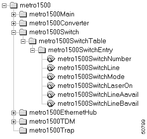
The SwitchEntry subtree, which is located under the SwitchTable heading (see Figure 4-6), describes the information on installed switches. The SwitchEntry subtree includes the following information:
Table 4-10 describes the variables.
| Subtree | Variable | Type | Description |
|---|---|---|---|
metro1500 | metro1500SwitchNumber | Integer | Switch number |
metro1500SwitchLine | Integer | Active switch line: | |
metro1500SwitchMode | Integer | Switch mode: | |
metro1500SwitchLaserOn | Integer | Reference laser status: | |
metro1500SwitchLineAavail | Integer | Line A availability: | |
metro1500SwitchLineBavail | Integer | Line B availability: |
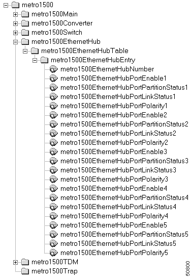
The EthernetHubEntry subtree, which is located under the EthernetHubTable (see Figure 4-7), describes status information for all of the ports and data communications on the Ethernet hub. (See Table 4-11.)
 |
Note The five ports on the Ethernet hub support connections from up to four NEMIs (one NEMI-master and up to three NEMI-slaves) in the network element. This leaves one port free for an external Ethernet connection to the platform that runs the network management system (NMS). |
| Subtree | Variable | Type | Description |
|---|---|---|---|
metro1500EthernetHubEntry | EthernetHubNumber | Integer | Ethernet hub slot number |
| The following information applies to ports 2, 3, 4, and 5. | |||
metro1500EthernetHubEntry | EthernetHubPortEnable1 | Integer | Port 1 is enabled/disabled by software; valid values are: |
EthernetHubPortPartition | Integer | Port 1 is partitioned/not partitioned by hardware; valid values are: | |
EthernetHubPortLink | Integer | Status of data connection on port 1 (receipt of link pulses); valid values are: | |
EthernetHubPortPolarity1 | Integer | Polarity of input signal on port 1; valid values are: | |
The TDMEntry subtree, which is located under the TDMTable (see Figure 4-8), describes information for the TMD4E module installed in the slot. The TDMEntry subtree includes status information on the data communication links on the remote and local side, as follows:
See Table 4-12.
 |
Note For the four-fold TDM4E module, there are four local links for the four sub-channels and one remote link. The TDM MUX/DMUX technology requires that the data be analyzed. Therefore, the true state of the data connection must be monitored, not just the receipt of an optical signal (modulated or otherwise). |

| Subtree | Variable | Type | Description |
|---|---|---|---|
metro1500 | TDMNumber | Integer | Slot number of the installed TDM4E module |
TDMRxRem | Integer | Status of remote receiver: receipt of light; valid values are: | |
TDMRxSync | Integer | Status of remote data connection: synchronization of signals; valid values are: | |
TDMTxRem | Integer | Status of remote transmitter; valid values are: | |
TDMTxRemC | Integer | Current of remote transmitter in milliamperes (only available if a current sensor is installed) | |
TDMTxRemTemp | Integer | Temperature of remote transmitter in degrees Fahrenheit/Celsius (only available if the remote transmitter is cooled) | |
TDMLocLoop | Integer | Status of local loop: applies to all channels; valid values are: | |
| The following information applies to local modules 2, 3, and 4. | |||
metro1500 | TDMLocModuleInst1 | Integer | Configuration state of module for sub-channel 1 on port 1: installation of a module; valid values are: |
TDMLocModuleEnabe1 | Integer | Configuration state of sub-channel 1: connection to the TDM data stream; valid values are: | |
TDMLocModuleRx1 | Integer | State of local receiver of sub-channel 1: receipt of data; valid values are: | |
TDMLocModuleTx1 | Integer | State of local transmitter in module 1; valid values are: | |
TDMLocModuleRemote | Integer | State of remote data connection for sub-channel 1: receipt of data from the TDM data stream; valid values are: | |
metro1500 | TDMLocModuleClock | Integer | Configuration state of local receiver in module 1: frequency of clock in Mbps |
TDMLocModuleClock | Integer | State of local receiver for sub-channel 1: clock recovery error; valid values are: | |
Failures of equipment and communication channels, and changes in state are monitored by the SNMP agent and stored in log files. SNMP traps are sent over the network to the defined trap sinks. SNMP traps include:
See Table 4-13 for a description of the SNMP log files.
| Log File | Description |
|---|---|
/etc/FlashLog.log | Events are logged permanently. |
/temp/RAMLog.log | Events are logged in memory. This log file is erased every time the NEMI reboots. |
To see the logged events, enter either:
less /temp/RAMLog.log
or
less /etc/FlashLog.log
In the case of errors, traps are sent automatically to the IP addresses defined as trap sinks. The trap sinks are configured to accept traps of a certain priority level or above. These traps allow you to monitor and log relevant events.
These traps deliver a slot number, power supply number or fan number. For information about how the power supplies and fans are numbered, see the "Power Supply and Fan Numbering" section. Table 4-14 lists main system traps.
| Trap No. | Trap Name | Variable | Description | Default Priority |
|---|---|---|---|---|
1 | metro1500HardwareAdded | metro1500SlotNumber | Hardware is added to the system. | 1 |
2 | metro1500HardwareDeleted | metro1500SlotNumber | Hardware is deleted from the system. | 1 |
3 | metro1500PSNotFail | metro1500PSNumber | Power supply starts working. | 4 |
4 | metro1500PSFail | metro1500PSNumber | Power supply fails. | 4 |
5 | metro1500FanNotFail | metro1500FanNumber | Fan starts working. | 4 |
6 | metro1500FanFail | metro1500FanNumber | Fan fails. | 4 |
7 | metro1500BusNotFail | - | Internal bus starts working. | 4 |
8 | metro1500BusFail | - | Internal bus fails. | 4 |
These traps deliver status information by slot number for local and remote receivers and transmitters, as well as for the clock and local loop. Table 4-15 lists the converter card traps.
| Trap No. | Trap Name | Variable | Description | Default Priority |
|---|---|---|---|---|
20 | metro1500RxLocOn | metro1500SlotNumber | Local receiver is on. | 4 |
21 | metro1500RxLocOff | metro1500SlotNumber | Local receiver is off. | 4 |
22 | metro1500TxLocOn | metro1500SlotNumber | Local transmitter is on. | 20 |
23 | metro1500TxLocOff | metro1500SlotNumber | Local transmitter is off. | 20 |
24 | metro1500RxRemOn | metro1500SlotNumber | Remote receiver is on. | 4 |
25 | metro1500RxRemOff | metro1500SlotNumber | Remote receiver is off. | 4 |
26 | metro1500TxRemOn | metro1500SlotNumber | Remote transmitter is on. | 20 |
27 | metro1500TxRemOff | metro1500SlotNumber | Remote transmitter is off. | 20 |
28 | metro1500RxRem2On | metro1500SlotNumber | 2nd remote receiver is on. | 4 |
29 | metro1500RxRem2Off | metro1500SlotNumber | 2nd remote receiver is off. | 4 |
30 | metro1500TxRem2On | metro1500SlotNumber | 2nd remote transmitter is on. | 20 |
31 | metro1500TxRem2Off | metro1500SlotNumber | 2nd remote transmitter is off. | 20 |
32 | metro1500ClockNoFail | metro1500SlotNumber | Clock is working. | 4 |
33 | metro1500ClockFail | metro1500SlotNumber | Clock fails. | 4 |
34 | metro1500ClockChange | metro1500SlotNumber | Multifrequency clock changes frequency. | 4 |
35 | metro1500LocLoopOff | metro1500SlotNumber | Local loop is off. | 4 |
36 | metro1500LocLoopOn | metro1500SlotNumber | Local loop is on. | 4 |
37 | metro1500RemLoopOff | metro1500SlotNumber | Remote loop is off. | 4 |
38 | metro1500RemLoopOn | metro1500SlotNumber | Remote loop is on. | 4 |
These traps deliver status information by slot number for reference laser, switch, and lines A and B. Table 4-16 lists the switch traps.
| Trap No. | Trap Name | Variable | Description | Default Priority |
|---|---|---|---|---|
40 | metro1500switchReference | metro1500SlotNumber | Reference laser is switched on. | 4 |
41 | metro1500switchReference | metro1500SlotNumber | Reference laser is switched off. | 4 |
42 | metro1500switchtoA | metro1500SlotNumber | Switch goes to line A. | 4 |
43 | metro1500switchtoB | metro1500SlotNumber | Switch goes to line B. | 4 |
44 | metro1500switchAutomatic | metro1500SlotNumber | Switch goes to automatic mode. | 4 |
45 | metro1500switchLocked | metro1500SlotNumber | Switch goes to locked mode. | 4 |
46 | metro1500switchLineAavail | metro1500SlotNumber | Line A is now available. | 4 |
47 | metro1500switchLineA | metro1500SlotNumber | Line A is not available. | 4 |
48 | metro1500switchLineBavail | metro1500SlotNumber | Line B is now available. | 4 |
49 | metro1500switchLineB | metro1500SlotNumber | Line B is not available. | 4 |
Trap number 50 (see Table 4-17) halts a flood of on or off traps that might occur under certain conditions where a connection is imperfectly maintained. This trap references the module by slot number, power supply number, or fan number.
| Trap No. | Trap Name | Variable | Description | Default Priority |
|---|---|---|---|---|
50 | metro1500repeatedMessage | metro1500SlotNumber/PSNumber/FanNumber | If the same trap has been sent three times, this trap is sent in place of the fourth repeat. Thereafter, the original trap is suppressed for one minute. | 1 |
Traps number 51 and 52 report whether the INNC is up or down. See Table 4-18.
| Trap No. | Trap Name | Description | Default Priority |
|---|---|---|---|
51 | metro1500INNCDown | Inter-NEMI network connection is down. | 1 |
52 | metro1500INNCUp | Inter-NEMI network connection is up. | 1 |
These traps report by slot number whether the Ethernet hub is enabled, partitioned, and is receiving link pulses. See Table 4-19.
| Trap No. | Trap Name | Variable | Description | Default Priority |
|---|---|---|---|---|
60 | EthernetHubPortEnable | SlotNumber | A port of the Ethernet hub is enabled by software. Use SNMP Get command to get the port number. | 4 |
61 | EthernetHubPortDisable | SlotNumber | A port of the Ethernet hub is disabled by software. Use SNMP Get command to get the port number. | 4 |
62 | EthernetHubPortPartitioned | SlotNumber | A port of the Ethernet hub is disabled by hub hardware. Use SNMP Get command to get the port number. | 4 |
63 | EthernetHubPortNotPartitioned | SlotNumber | A port of the Ethernet hub is enabled by hub hardware. Use SNMP Get command to get the port number. | 4 |
64 | EthernetHubPortLinkPulses | SlotNumber | A port of the Ethernet hub starts to receive link pulses. Use SNMP Get command to get the port number. | 4 |
65 | EthernetHubPortNoLinkPulses | SlotNumber | A port of the Ethernet hub stops receiving link pulses. Use SNMP Get command to get the port number. | 4 |
These traps deliver status information by slot number for the TDM4E modules installed in the system. They report loss of data connection, whether local modules are enabled, status of local receivers, receipt of remote data, and status of local clock recovery. See Table 4-20.
| Trap No. | Trap Name | Variable | Description | Default Priority |
|---|---|---|---|---|
70 | RemoteSyncLoss | SlotNumber | Loss of data connection (no synchronization) on a remote link. | 4 |
71 | RemoteSynch | SlotNumber | Synchronization is re-established on a remote link. | 4 |
72 | LocModuleEnable1 | SlotNumber | Local module 1 is enabled by software. | 4 |
73 | LocModuleDisable1 | SlotNumber | Local module 1 is disabled by software. | 4 |
74 | LocModuleEnable2 | SlotNumber | Local module 2 is enabled by software. | 4 |
75 | LocModuleDisable2 | SlotNumber | Local module 2 is disabled by software. | 4 |
76 | LocModuleEnable3 | SlotNumber | Local module 3 is enabled by software. | 4 |
77 | LocModuleDisable3 | SlotNumber | Local module 3 is disabled by software. | 4 |
78 | LocModuleEnable4 | SlotNumber | Local module 4 is enabled by software. | 4 |
79 | LocModuleDisable4 | SlotNumber | Local module 4 is disabled by software. | 4 |
88 | LocModuleRxOn1 | SlotNumber | Local receiver for sub-channel 1 has received modulated signal. | 4 |
89 | LocModuleRxOff1 | SlotNumber | Local receiver for sub-channel 1 has lost modulated signal. | 4 |
90 | LocModuleRxOn2 | SlotNumber | Local receiver for sub-channel 2 has received modulated signal. | 4 |
91 | LocModuleRxOff2 | SlotNumber | Local receiver for sub-channel 2 has lost modulated signal. | 4 |
92 | LocModuleRxOn3 | SlotNumber | Local receiver for sub-channel 3 has received modulated signal. | 4 |
93 | LocModuleRxOff3 | SlotNumber | Local receiver for sub-channel 3 has lost modulated signal. | 4 |
94 | LocModuleRxOn4 | SlotNumber | Local receiver for sub-channel 4 has received modulated signal. | 4 |
95 | LocModuleRxOff4 | SlotNumber | Local receiver for sub-channel 4 has lost modulated signal. | 4 |
104 | LocModuleData1 | SlotNumber | Sub-channel 1 has received remote data (transmission on). | 4 |
105 | LocModuleNoData1 | SlotNumber | Sub-channel 1 has lost remote data (transmission on). | 4 |
106 | LocModuleData2 | SlotNumber | Sub-channel 2 has received remote data (transmission on). | 4 |
107 | LocModuleNoData2 | SlotNumber | Sub-channel 2 has lost remote data (transmission on). | 4 |
108 | LocModuleData3 | SlotNumber | Sub-channel 3 has received remote data (transmission on). | 4 |
109 | LocModuleNoData3 | SlotNumber | Sub-channel 3 has lost remote data (transmission on). | 4 |
110 | LocModuleData4 | SlotNumber | Sub-channel 4 has received remote data (transmission on). | 4 |
111 | LocModuleNoData4 | SlotNumber | Sub-channel 4 has lost remote data (transmission on). | 4 |
120 | LocModuleClockFail1 | SlotNumber | Local clock recovery failure on (receiver of) sub-channel 1. | 4 |
121 | LocModuleClockNoFail1 | SlotNumber | Local clock recovery no failure on (receiver of) sub-channel 1. | 4 |
122 | LocModuleClockFail2 | SlotNumber | Local clock recovery failure on (receiver of) sub-channel 2. | 4 |
123 | LocModuleClockNoFail2 | SlotNumber | Local clock recovery no failure on (receiver of) sub-channel 2. | 4 |
124 | LocModuleClockFail3 | SlotNumber | Local clock recovery failure on (receiver of) sub-channel 3. | 4 |
125 | LocModuleClockNoFail3 | SlotNumber | Local clock recovery no failure on (receiver of) sub-channel 3. | 4 |
126 | LocModuleClockFail4 | SlotNumber | Local clock recovery failure on (receiver of) sub-channel 4. | 4 |
127 | LocModuleClockNoFail4 | SlotNumber | Local clock recovery no failure on (receiver of) sub-channel 4. | 4 |
Telnet is a terminal emulation program that allows you to link into UNIX systems. The basic Telnet protocol specification is defined in RFC 854. Use Telnet to run the following two commands:
Use ocmstate to gather basic status information about the system. Use snmpconfig to configure SNMP parameters for up to ten network managers.
 |
Note You need a username and password to use Telnet to log into the UNIX server. |
 |
Note Another version of Telnet, called dtelnet (for Dave Cole's Telnet), is also available. For details about dtelnet, log onto http://dtelnet.sourceforge.net. For installation instructions for dtelnet, see the "Installi ng dtelnet" section. |
After logging in, use the ocmstate program to get basic information on the system. In addition to displaying serial number, device code, software version of the NEMI, and the hardware and software versions of the device master, ocmstate also provides the fixed parameters of the modules and converter cards.
ocmstate provides options that allow you to customize the information display, update output, and change settings. For a listing of ocmstate options, see Table 4-21. For an example of output from the ocmstate -o option, see Figure 4-9.
| Option | Description |
|---|---|
-BG | Displays lines reversed to simulate syntax highlighting, which indicates that some card settings are different from the default. |
-c | Provides serial numbers and device codes for chassis. |
-e | Puts you in expert mode so you can change loop, transmitter, and (if installed) clock settings. |
-f | Provides status information about the power supply and fans. |
-l | Displays detailed information about installed channel modules and the status of all local and remote receivers and transmitters. Note The -BG option can also be used with the -l option; for example: ocmstate -l -BG |
ocmstate -o | Displays ocmstate options. |
ocmstate -p | Forces ocmstate to update its output periodically. |
ocmstate -s | Displays status information for transmitters and receivers. |
ocmstate -slot-number | Provides information for the slot number specified. |
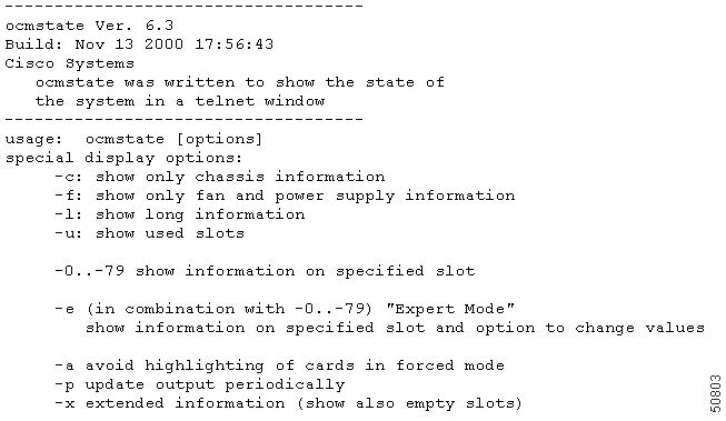
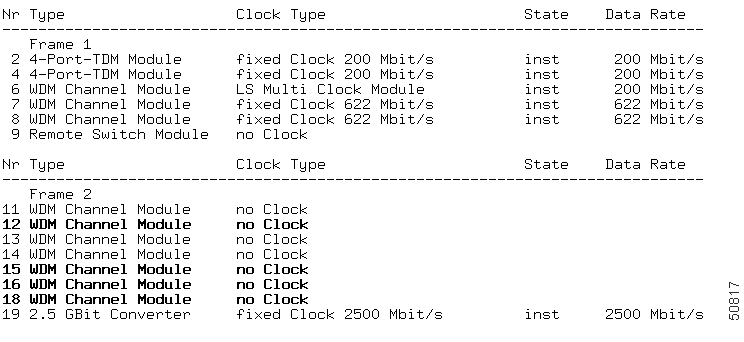
Figure 4-10 shows standard output from the ocmstate command. Highlighted lines indicate settings that have been changed from the default. For Windows, use the ocmstate -BG command.
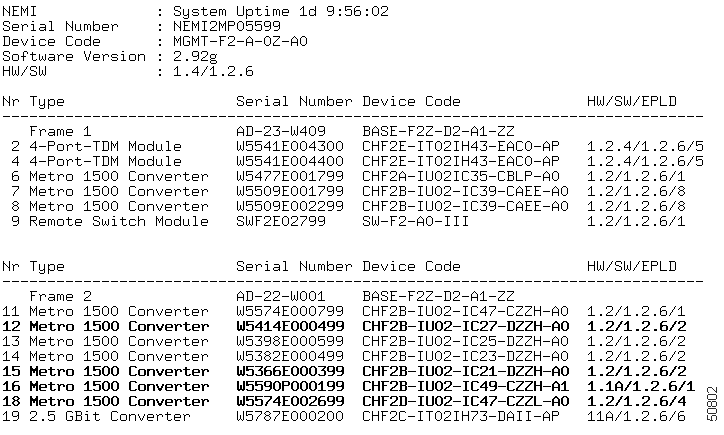
For more detailed information about the installed WCMs, including the status of all local and remote receivers, use the ocmstate -l option. (See Figure 4-11). Use the ocmstate -p option to force ocmstate to update its output periodically. For Windows, use the ocmstate -l -BG command.
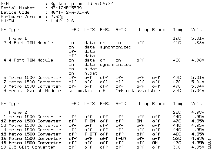
The ocmstate -l option displays the following information:
synchronized indicates that the remote data stream contains TDM information. data or n.data (no data) indicates whether the remote data stream contains information for this channel. on or off gives the status of the light on the local receiver.F-ON means the L-TX (local transmitter) is forced on, and on indicates the local loop (LLoop) has been set to on.The ocmstate -c option displays serial numbers and device codes for the chassis. See Figure 4-12.
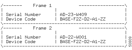
The ocmstate -f option displays status information for the power supply and fans. See Figure 4-13.

The ocmstate -slot-number option displays information for the slot number specified. See Figure 4-14.

To change any configuration settings, use ocmstate -e slot-number, which puts you into expert mode. For example, if your system has a multiclock installed and you enter:
ocmstate -e -3
the system displays information for slot 3, with the settings that can be changed while in expert mode. See Figure 4-15.
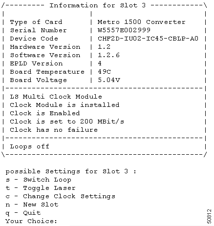
Select s to view and change executed loop settings for the slot specified.
See Figure 4-16.

Enter t at the Your Choice: prompt (see Figure 4-16) to display laser settings for the slot specified. See Figure 4-17.

If a multiclock is installed, select c to display clock settings for the slot specified and options for changing those settings. See Figure 4-18.

While in expert mode, you can also set the remote switch module (RSM). For example, if the RSM is installed in slot 29, and you enter the ocmstate -e -29 command, the system displays serial number, device code, and version information for the RSM. From this display, you can change the RSM settings. See Figure 4-19.

If you change the lock/unlock settings, you see a short report.
To set the multiclock directly, use the ocmstate -k or clockset command. Figure 4-20 shows sample output from the clockset command.
While netconfig customizes SNMP for just one network manager address with a standard configuration, snmpconfig fine tunes the SNMP parameters. The snmpconfig command can address up to 10 network managers. Events and managers can be configured with different priorities to adjust the SNMP behavior to your requirements. Log files are treated in the same way as network manager addresses.
Events have assignable priorities ranging from 1 (very important), 10 (informal), and 20 (do not report).
Trap sink reporting and logging into the log files is controlled by assigning these trap sinks and log files a reporting level with the same range from 1 to 10.
For example, a trap sink with reporting level 1 receives only events that have been assigned priority 1 and a trap sink with reporting level 10 receives all events that have been assigned priorities from 1 to 10.
Enter the snmpconfig command to display the main screen, which shows most of the SNMP settings. (See Figure 4-21.)
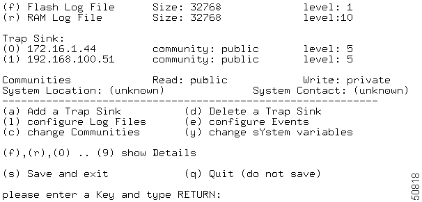
The first two lines of the main screen describe the log file settings. While the RAM log file has the reporting level 10 (get all events), the Flash log file only receives important information (level 1). Two trap sinks (SNMP managers that receive SNMP traps) are assigned reporting level 5.
There is also an option for setting the community strings for read and write access, and for setting the SNMP variables sysLocation (system location) and sysContact (system contact).
Use the following snmpconfig commands to fine tune the SNMP parameters for the network:
While the previous settings are only used for reporting SNMP traps, the next four settings change the behavior for SNMP get and set instructions.
The read community string is used for any SNMP get or getnext instruction. The instruction is only answered by the SNMP agent on the correct (read or write) community string.
The write community string is sent with every SNMP set instruction. The instruction is only executed on the correct write community string to establish security for SNMP.
 |
Note Using the wrong community string will generate an "Authentication Failure" trap. |
The standard SNMP variables, system location and system contact, are defined in RFC 1213. They manage SNMP agents on large networks. System location should be a short string that describes the location of the SNMP agent. System contact is the person who is responsible for this agent. These values can be set by snmpconfig. Enter s, save and exit, to store these settings.
 |
Note The computer must be rebooted for these settings take effect. |
dtelnet is a Telnet client licensed from GNU Copyleft. To facilitate installation, the original dtelnet.zip package has been repackaged as dtelnet.exe (a self-extracting ACE archive).
To install dtelnet, follow these steps:
Step 1 Make sure that you can connect to the Cisco Metro 1500 series system by serial port and PPP or by Ethernet.
Step 2 Create a home directory or folder for dtelnet.
Step 3 Open the folder and start FTP (file transfer protocol).
Step 4 Log into the netadmin account and transfer adtelnet.exe in binary mode to the folder you have set up.
Step 5 Execute adtelnet.exe, which extracts the following files:
Step 6 Log out of the netadmin account and quit FTP.
Step 7 Delete adtelnet.exe and start using dtelnet.exe as your Telnet client.
![]()
![]()
![]()
![]()
![]()
![]()
![]()
![]()
Posted: Sat Sep 28 02:43:13 PDT 2002
All contents are Copyright © 1992--2002 Cisco Systems, Inc. All rights reserved.
Important Notices and Privacy Statement.