|
|

This chapter provides an overview of the Cisco Metro 1500 series metropolitan area network (MAN) dense wavelength division multiplexing (DWDM) system. This chapter includes the following sections:
In wavelength division multiplexing (WDM), multiple optical signals are transmitted on a single optical fiber using different wavelengths. WDM assigns incoming optical signals to specific frequencies of light (wavelengths or lambdas) within a certain frequency band. This multiplexing closely resembles the way radio stations broadcast on different wavelengths without interfering with each other. Because each channel is transmitted at a different frequency, you can use a tuner to select from them. In WDM, each channel is a different color of light; several channels then make up a "rainbow."
 |
Note The term wavelength is used instead of the term frequency to avoid confusion with other uses of frequency. Wavelength is often used interchangeably with lambda and channel. |
Each of the wavelengths is independently injected into the fiber and the signals are demultiplexed at the receiving end. Like time-division multiplexing (TDM), the resulting capacity is an aggregate of the input signals, but WDM carries each input signal independently of the others. This means that each channel has its own dedicated bandwidth; all signals arrive at the same time, rather than being broken up and carried in time slots.
Dense wavelength division multiplexing (DWDM) systems support a large number of channels. The difference between DWDM and WDM is fundamentally one of degree. DWDM spaces the wavelengths more closely than does WDM, and therefore has a greater overall capacity. With DWDM you can amplify all the wavelengths at once without first converting them to electrical signals. You can also carry signals of different speeds and types simultaneously and transparently over the fiber, thus providing protocol and bit rate independence.
Most DWDM systems support standard SONET/SDH short-reach optical interfaces to which any SONET/SDH compliant "client" device can attach. In today's long-haul WDM systems, this is most often an OC-48c/STM-16c interface operating at a wavelength of 1300 nm. The clients may be SONET/SDH terminals or add/drop multiplexers (ADMs), ATM switches, or routers.
Within the DWDM system, a transponder converts the SONET/SDH compliant optical signal from the client back to an electrical signal. This electrical signal is then used to drive a WDM laser. The WDM laser is a very precise laser operating within the 1500-nm wavelength range. Each transponder within the system converts its client's signal to a slightly different wavelength. The wavelengths from all of the transponders in the system are then optically multiplexed onto a single fiber.
In the receive direction of the DWDM system, the reverse process takes place. Individual wavelengths are filtered from the multiplexed fiber and fed to individual transponders, which convert the signal to electrical and drive a standard SONET/SDH interface to the client.
The Cisco Metro 1500 series system is a high-performance, wavelength division multiplexer for bidirectional data communication. It is designed for communication over optical links in which different devices or applications are communicating over multiple fibers. Using wavelength conversion, several devices can communicate while being connected over one duplex fiber or two single fibers.
The base configuration of the Cisco Metro 1500 series system consists of a primary chassis that holds the following modules:
|
Note For detailed descriptions of these modules, refer to the Cisco Metro 1500 Series Hardware Installation Guide. |
The Cisco Metro 1500 series system is available in the following configurations:
The Cisco Metro 1500 series system can be expanded in increments of eight WCMs by adding extension chassis. A maximum of three extension chassis (designated A through C) can be added to the primary chassis to bring the total channel capacity of the system to 32 WCMs housed in four chassis.
(See Figure 1-1.)

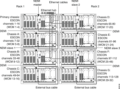
Adding four additional chassis (designated D through G) in a second rack upgrades the system to transport a total of 128 independent ESCON channels, using 32 double-width TDM4E channels. The band splitter module, which combines and splits up to four groups of multiplexed optical channels, is housed in extension chassis B. (See Figure 1-2.)
|
Note We recommend that you arrange the extension chassis under the primary chassis as shown in Figure 1-1 and Figure 1-2. |
Standard Internet protocols connect the system's network management system (NMS) to external management systems. The Ethernet port or the serial port on each NEMI module provides the physical connection to the network. A multiport Ethernet hub is necessary for systems with more than two chassis. This hub connects two or more NEMI modules together. It provides network management from a single point in the network through a single IP address. The Simple Network Management Protocol (SNMP) provides the interface to an external NMS.
The network element management interface (NEMI) is a plug-in module that is inserted into the system's primary chassis (in a 16-channel system) and extension chassis B (in 32-channel and 128-channel systems). This interface uses Internet protocols to provide management and configuration capabilities. A NEMI network management system can be connected through an Ethernet connection to a computer or a local area network. An EIA/TIA-232 port is available on the panel of a NEMI, which can be used for serial-based setup and can be configured to deliver serial- or modem-based Internet protocol connectivity and management with Point-to-Point Protocol (PPP) support. The NEMI runs the Linux 2.0.35 operating system.
The device element management interface (DEMI) is a plug-in module that can be inserted into the system's extension chassis A (in a 16-channel system) and extension chassis C (in 32-channel and 128-channel systems). This interface provides status and monitoring capabilities. An external bus cable connects the NEMI to its DEMI. This configuration unites management and control of both chassis into a single unit.
For information about configuring the NEMI modules, see "NEMI Operation."
|
Note This section includes information that only pertains to NEMI software version 3.0. |
See Table 1-1 for the NEMI's factory configured default settings.
| Option | Settings |
|---|---|
RS-232 port settings | 19200 baud1 8 bits No parity 1 stop bit Hardware handshaking |
Ethernet address | 192.168.168.168 |
Hostname | Unknown |
User accounts | root, netadmin, ppp, user |
Account passwords | All account passwords are factory set to ChgMeNOW |
Installed software | Linux 2.0.35 Slackware distribution |
| 1We recommend operating at 9600 baud. |
Figure 1-3 shows the configuration of a fully populated 16-channel system that consists of the primary chassis and extension chassis A. The primary chassis contains the configurable NEMI module. Extension chassis A contains the DEMI module, which monitors the functioning of the extension chassis. The DEMI module has no configuration requirements.
Each NEMI/DEMI pair is interconnected by an external bus cable that passes management and configuration control information between the two chassis. The NEMI and DEMI bind the two physical chassis into a single logical management unit consisting of 16 channels.
For information about configuring the NEMI modules, see "NEMI Operation."
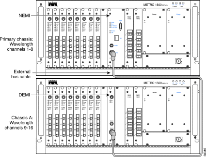
Figure 1-4 shows the configuration of a fully populated 32-channel system that consists of the primary chassis and three extension chassis. The primary chassis contains the configurable NEMI module. Extension chassis A and B contain the DEMI modules, which monitor the functioning of the extension chassis. The DEMI modules have no configuration requirements.
The NEMI in the primary chassis is connected to the DEMI in extension chassis A. The NEMI in extension chassis B is connected to the DEMI in extension chassis C. Each NEMI/DEMI pair is interconnected by an external bus cable that passes management and configuration control information between the two chassis.
Through their Ethernet ports, both NEMI modules are connected to an Ethernet hub with Ethernet cables. Both NEMI modules use these Ethernet connections to pass management and configuration data. The two 16-channel systems operate as a single 32-channel system.
When two 16-channel systems are connected in this way, the NEMI in the primary chassis is configured as the NEMI master and the NEMI in extension chassis B is configured as the NEMI slave. When these two 16-channel systems are properly configured, the NEMI master/slave configuration provides identical views of a single 32-channel logical management unit.
For information about configuring the NEMI modules, see "NEMI Operation."
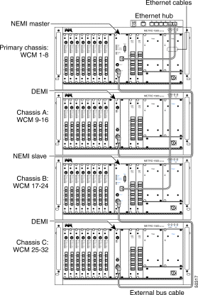
Figure 1-5 shows the physical configuration of a fully populated 128-channel ESCON system with 32-channel TDM4E modules. The 128-channel system consists of a primary chassis and seven extension chassis. This configuration requires two racks. The primary chassis and extension chassis B, D, and F are equipped with NEMI modules. Extension chassis A, C, E, and G are equipped with DEMI modules.
The first NEMI module, which is installed in the primary chassis, is configured as the NEMI master and the other three NEMI modules are all configured as NEMI slaves. All four NEMI modules are connected by their Ethernet ports to an Ethernet hub. When the eight chassis are configured properly, they are a single unified network element with a unique Ethernet address. For information on configuring the NEMI modules, see "NEMI Operation."
![]()
![]()
![]()
![]()
![]()
![]()
![]()
![]()
Posted: Sat Sep 28 02:43:32 PDT 2002
All contents are Copyright © 1992--2002 Cisco Systems, Inc. All rights reserved.
Important Notices and Privacy Statement.