|
|

Table Of Contents
Operation
This chapter describes the operation of the NEMI, and includes the following sections:
•
Overview
•
•
Overview
The NEMI can be accessed through the network in three different ways: SNMP, Telnet, or FTP.
You can monitor the state of the connected chassis of the Cisco Metro 1500 series system most effectively with SNMP. With a small amount of network traffic, you can read the complete state of the chassis. Events are reported immediately to a management station.
To configure the system or to see a detailed view of a component, you can use Telnet or HyperTerminal with a Laplink cable. After logging in to the NEMI, you can process commands to read or to configure values.
Use FTP for file transfer between the NEMI and your management station. For example, when loading the Management Information Base (MIB) file from the NEMI to your management station or when doing software updates on the NEMI.
SNMP
SNMP defines three ways for a network management system to communicate to a network element:
•
•
•
Events are reported by the network element with an SNMP trap.
Variables are located in a tree-like structure and coded with Abstract Syntax Notation One (ASN.1). The variable 1.3.6.2.1.1.1.0 is the system description, defined in RFC 1213. To make the SNMP values human readable, a MIB file containing names for the variables is supplied. RFC 1213 contains a MIB file for some standard variables. Using RFC 1213, the variable 1.3.6.2.1.1.1.0 is iso.org.dod.internet.mgmt.mib-2.system.sysDescr.0. Vendors of network elements that use nonstandard variables must supply customers with their private MIB file. The Cisco Metro 1500 series MIB file is posted at ftp://ftp.cisco.com/pub/mibs.
The Cisco Metro 1500 series system can be managed by any network management program that supports SNMP.
SNMP Variables
The NEMI supports the variables defined in RFC 1213. The most often used variables in system tree 1.3.6.2.1 are sysDescr, sysName, sysContact, and sysLocation. The variable sysDescr is a unique text string that is always
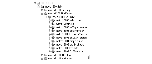
"Metro 1500 Series." The variable sysName is the hostname of the system and is set by the netconfig command. The variables sysLocation and sysContact are where the system is located and who is responsible for it. The variables sysName and sysContact can be changed either by the snmpconfig command or by SNMP set instructions. In RFC 1213 there are many variables defined for interface statistics and routing tables. For detailed information, refer to RFC 1213 documentation.In addition to the standard variables, Cisco Metro 1500 series supports specific variables. The MIB tree has information on the housing management system and information common to all inserted slots. Figure 5-1 shows the complete MIB tree beginning from root.
Figure 5-1 MIB Tree
Using the SNMP manager, you can read the status values of the unit. The community string used to read the values is public. If you need to set values, use the community string private. Be careful with this community string, because every SNMP manager in the network can change status values of the unit when using the private community string. Refer to Table 5-1 through Table 5-6 for SNMP variables.
Housing
The Housing subtree ( Figure 5-2) describes the information on the main system and the internal bus system. Table 5-1 describes the variables.
Figure 5-2 Housing Subtree
Slot Table
The slot table subtree ( Figure 5-3) describes all the common values of the installed slots. Table 5-2 describes the variables.
Figure 5-3 Slot Table Subtree
Power Supplies and Fan
The power supply and fan subtrees ( Figure 5-4) have two variables: one contains the part number and the other contains the on/off status. Table 5-3 and Table 5-4 describe the variables.
Figure 5-4 Power Supply and Fan Subtrees
Channel Module
The channel module subtree ( Figure 5-5) contains information on the installed channel modules. Table 5-5 describes the variables.
Figure 5-5 Channel Module Subtree
Switch
The switch subtree ( Figure 5-6) contains the information on installed switches. Table 5-6 describes the variables.
Figure 5-6 Switch Subtree
SNMP Traps
Failures and changes in state are stored in log files. SNMP traps are sent to the defined trap sinks. See Table 5-7 for a description of the log files.
Table 5-7 SNMP Log Files
/etc/FlashLog.log
Events are logged permanently.
/temp/RAMLog.log
Events are logged in memory. This log file is erased every time the NEMI reboots.
Enter less /temp/RAMLog.log or less /etc/FlashLog.log to see the logged events.
In the case of errors, traps are sent automatically to the IP addresses defined as trap sinks. These traps deliver a slot number, a power supply number, or a fan number. Table 5-8 through Table 5-10 show a list of the error classes.
Telnet
The Telnet protocol is designed to work between any host and any terminal. It operates in a client/server environment in which one host negotiates a session on another host. During the negotiation process, the two hosts agree on the parameters governing the session. You need a username and password on the Telnet server. The base Telnet protocol specification is defined in RFC 854.
ocmstate
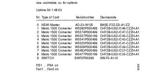
After logging in, you can use the ocmstate program to get basic information on the system. Figure 5-7 shows an example.
Figure 5-7 Output from ocmstate
Table 5-11 describes the ocmstate options.
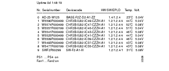
To get more information about the installed Wavelength Channel Modules (WCMs), you can enter ocmstate -l ( Figure 5-8). You can also use ocmstate -p, which forces ocmstate to update its output periodically.
Figure 5-8 Output from ocmstate -l
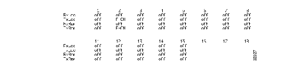
After entering ocmstate -s, you get information on the status of all local and remote receivers and transmitters ( Figure 5-9).
Figure 5-9 Output from ocmstate -s
To get the version information, enter ocmstate -?. Inputs with the format of ocmstate - # are also supported. Figure 5-10 shows the result of an ocmstate -3.
Figure 5-10 Output from ocmstate -3
Note
In expert mode you have the option to change the loop settings and the transmitter settings.
Figure 5-11 shows the output from the ocmstate -e -3 command.
Figure 5-11 Output from ocmstate -e -3
If you select s, you see the prompt as shown in Figure 5-12.
You can enter l or r to toggle the remote or local loop.
Figure 5-12 Loop Settings
If you select t, you see the prompt as shown in Figure 5-13.
Figure 5-13 Laser Settings
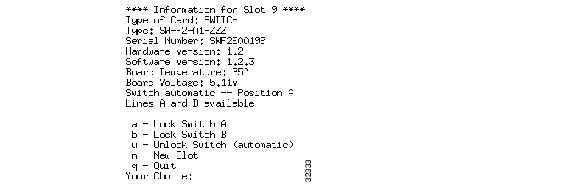
In expert mode you can also set the Remote Switch Module (RSM). If the RSM is installed at slot 9 and you enter ocmstate -e -9, the result is shown in Figure 5-14.
After execution of the lock or unlock command, you get a short report as shown in Figure 5-14.
Figure 5-14 Output from switchsetting
clockset
If you want to directly set multiclock options, use the clockset program. After typing clockset the main information screen appears.
Type in the desired slot number to view the card and receive options. A shortcut command is available for directly accessing cards in specific slots. Type the following to directly access a card in any given slot.
clockset-[slotnumber]
If you want to get version information, type clockset -?
snmpconfig
While netconfig is used to customize SNMP for just one network manager address with a standard configuration, snmpconfig is used for fine tuning the SNMP parameters. The snmpconfig command can address up to 10 network managers. Events and manager can be configured with different priorities to adjust the SNMP behavior to your requirements. Log files are treated in the same way as network manager addresses.
Events have assignable priorities ranging from 1 (very important), to 10 (informal), and 20 (don't report).
Trap sink reporting and logging into the log files is controlled by assigning to these receivers a reporting level with the same range from 1 to 10. See Figure 5-15.
By entering the snmpconfig command, you will get the main screen, which shows most of the SNMP settings ( Figure 5-15).
Figure 5-15 Main Screen
The first two lines of Figure 5-15 describe the settings of the log files. While the RAM log file has the priority 10 (get all events), the Flash log file gets only important information. Two trap sinks are defined (SNMP managers that receive SNMP traps) with priority 5. There is an option for setting the communities for read and write and to set system location and system contact, which is described later in this section.
Use the snmpconfig commands to fine tune the parameters for the network:
•
•
•
•
•
The previous settings are used for reporting SNMP traps, the next four settings change the behavior for the SNMP get and set instructions. The read community string is used for any SNMP get or getnext instruction. The instruction is only answered by the SNMP agent on the correct (read or write) community string. The write community string is sent with every SNMP set instruction. The instruction is only executed on the correct write community string. The community strings are used to increase security on SNMP.
The standard SNMP variables, system location and system contact, are defined in RFC 1213. They are used to manage SNMP agents on a large network. System location should be a short string that describes the location of the SNMP agent. System contact is the person who is responsible for this agent. These values can be set by snmpconfig. By entering s, save and exit, the settings are stored. The settings are activated after the next reboot.
Note
![]()
![]()
![]()
![]()
![]()
![]()
![]()
![]()
Posted: Tue Apr 26 05:59:07 PDT 2005
All contents are Copyright © 1992--2005 Cisco Systems, Inc. All rights reserved.
Important Notices and Privacy Statement.