|
|

Table Of Contents
Time Zone and Time Synchronization Settings
NEMI Serial Communication Settings
Simple Network Management Protocol Configuration
System Configuration
This chapter describes system configuration procedures for both the 16- and 32-channel systems. Included are the requirements and procedures for the physical connections of the hardware and the configuration of the network connection using the NEMI. This chapter includes the following sections:
•
NEMI 32 Channel Configuration
•
Note
Note
Required Materials
The following is required to configure the NEMI:
•
or
•
See Appendix A, "Cables and Cabling" for details on the cables that are used with the NEMI and DEMI modules.
Connections to the NEMI
This section describes the two types of NEMI connections:
Serial Connection
To connect a laptop computer to the NEMI you should use a LapLink cable. This cable contains all serial signals and has the handshake signals crossed. See Appendix A, "Cables and Cabling" for complete cable specifications.
Almost any serial communications program can be used, as long as it can be set to support the factory-default configuration. You can use HyperTerminal, available with Windows 95/98.
The following instructions assume the modem is connected to the COM2 or COM4 port, leaving the COM1 and COM3 ports available for the LapLink cable.
To connect a laptop computer to the NEMI, follow these steps:
Step 1
Step 2
The default settings are 19.2 kbps, 8 bits, no parity, 1 stop bit, hardware flow control. Cisco recommends using 9600 baud. Save these settings for future use.
Step 3
If the NEMI is powered on, the cable is connected properly with the NEMI DB9 linked to the laptop DB9, and the serial line port settings are correct, you should see the Linux login greeting:
unknown loginA NEMI serial connection is shown in Figure 4-1. Next, proceed to the "Logging into the NEMI" section.
Figure 4-1 NEMI Serial Connection
Ethernet Connection
The NEMI's ethernet address is set by default to 192.168.168.168 and the subnet mask is set to 255.255.255.0. Follow these steps to connect to the NEMI using an ethernet connection:
Step 1
Step 2
Step 3
telnet 192.168.168.xxx <Enter>If the NEMI is powered on and the cable is connected properly you should see the Linux login greeting:
unknown login:A NEMI ethernet connection is shown in Figure 4-2. Next, proceed to the "Logging into the NEMI" section.
Figure 4-2 NEMI Ethernet Connection
Logging into the NEMI
Once connected to the NEMI, you can log in as one of the following accounts: root, netadmin, or user.
Note
User root can change the passwords for everybody. For example, to change the password for the netadmin user, type the following:
passwd netadminFor administration we recommend using the netadmin account. System setup, typically done once per system, requires root privileges that are obtained with the super user (su) command. The su command prompts the user for the root password.
System Configuration
The following sections describe the configuration steps required for both the 16 and 32 Channel systems. The steps to configure the 32 Channel system are documented in the "NEMI 32 Channel Configuration" section.
16 Channel Configuration
The primary chassis of the 16 Channel system includes the NEMI module and the extension chassis contains the DEMI module. Both the NEMI and DEMI have to be interconnected using an external bus cable. In this configuration, only the NEMI is configured. Figure 4-3 shows the physical configuration of the
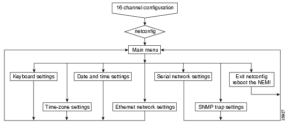
Cisco Metro 1500 series 16 Channel system and Figure 4-4 shows the software configuration steps flowchart.Figure 4-3 Cisco Metro 1500 Series 16 Channel System Configuration
Figure 4-4 Cisco Metro 1500 Series 16 Channel System Configuration Steps Flowchart
netconfig Command Options
.To configure the NEMI you'll use the netconfig command as follows:
netconfig <Enter>
Depending on your terminal emulation (Telnet or Hyper Terminal), the screen output may be appear differently from one connection type to the other.
Note
Be sure that your screen windows are as large as possible. Change the terminal emulation of the NEMI by typing either TERM=vt100, TERM=linux, or TERM=ansi. The netconfig screens are best viewed with Microsoft's Telnet application using TERM=vt100. The netconfig Menu screen is shown in Figure 4-5.
Figure 4-5 netconfig Menu Screen
Keymap Settings
By default, the NEMI comes configured for a U.S. keyboard. Use the netconfig command to change the keyboard setting permanently if you are not operating in a U.S. language environment. See Figure 4-5 and Figure 4-6.
Figure 4-6 Example of Azerty Keyboard Map
It takes a few moments to load the keyboard mapping files. Once you have selected the appropriate keyboard map, use the netconfig test mode to verify that you have chosen the correct mapping.
If you have selected an incorrect keymap, use one of the following commands to correct the problem:
•
•
Note
Time Zone and Time Synchronization Settings
The NEMI supports the Network Time Protocol (NTP). NTP synchronizes the time of a computer client or server to another server or reference time source. The time source can be a radio or satellite receiver or modem. NTP provides client accuracies typically within a millisecond on LANs and up to a few tenths of a millisecond on WANs relative to a primary server synchronized to Coordinated Universal Time (UTC) through a global positioning service (GPS) receiver. Typical NTP configurations utilize redundant servers and diverse network paths to achieve high accuracy and reliability. Some configurations include cryptographic authentication to prevent accidental or malicious protocol attacks.
Note
NTP has many options that depend on the time server setup. You need to be familiar with NTP, the Cisco Metro 1500 series system configuration, and the networking options to complete this setup.
To setup the NTP, follow these steps:
Step 1
Step 2
Note
Figure 4-7 Time-Zone Configuration
Step 3
Step 4
Step 5
Step 6
Step 7
Date Settings
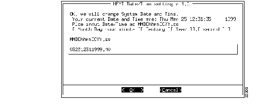
The NEMI sets the date and time using numbers only. To set the date and time, follow these steps:
Step 1
Step 2
Step 3
Figure 4-8 Date and Time Setting Screen
Note
Network Configuration
To configure the NEMI for use on an IP network, ask your network administrator for the following information and fill in the blank form available in the
Cisco Metro 1500 Series Operations Guide:•
•
•
•
•
•
•
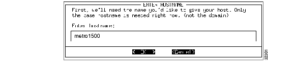
Once you have the necessary information (see Appendix B, "IP Addresses") log into the NEMI using the netadmin account. Enter the su command to gain root privilege and use the Netconfig command from the netconfig main menu to enter the above values. This procedure configures the network side of the NEMI. See Figure 4-9 through Figure 4-15 for the configuration screens.
Figure 4-9 Enter Host Name Screen
Figure 4-10 Enter Domain Name Screen
Figure 4-11 Enter Local IP Address Screen
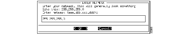
Figure 4-12 Enter Netmask Screen
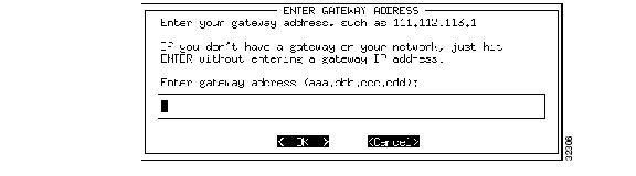
Figure 4-13 Enter Gateway Address Screen
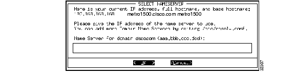
Figure 4-14 Select Nameserver Screen
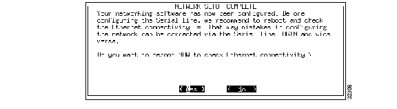
Figure 4-15 Network Setup Complete Screen
Check your work carefully, and then enter the reboot command to have the new network settings take effect.
After this reboot, if the correct IP addresses and masks have been defined, the NEMI shows up on the network. To test the success of the NEMI network configuration, try to ping the NEMI from another computer that is connected to the same network as the NEMI.
For example, from a Windows 95/98 system, open a DOS window and enter the ping xx.xx.xx.xx command, where xx.xx.xx.xx is the Host IP address you entered during the network configuration of the NEMI. If you receive a time-out message, either the NEMIs ethernet settings are not correct or there is a hardware problem.
NEMI Serial Communication Settings
You can use the NEMIs serial port in three different ways:
1.
2.
3.
Cisco recommends using PPP and a network protocol over the serial line at 9600 baud.
The following illustrations provide an overview of the process of configuring the serial settings. Select the ConSerial option from the netconfig menu screen to access these options.
Figure 4-16 Serial Settings Screen
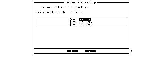
Figure 4-17 Serial Speed Setup Screen
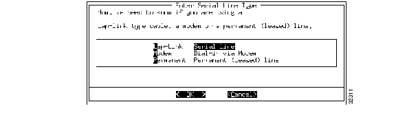
Figure 4-18 Serial Line Type Screen
Figure 4-19 PPP Usage Screen
If you dial-in with a modem or leased line, Cisco recommends using PPP. PPP establishes a network connection similar to an ethernet connection. You have to enter the IP addresses for both sides of the PPP connection and the netmask.
Figure 4-20 Remote IP Address Screen
The remote system can either be a terminal concentrator or a network management system which are connected to the other side of the PPP connection. Since PPP has only two stations on the network, the netmask can be automatically set by the computer. However, you can save address space by setting the subnet mask manually. See Figure 4-21 and Figure 4-22.
Figure 4-21 Netmask for PPP Screen
Figure 4-22 Enter Netmask for PPP Screen
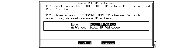
For a typical configuration, the NEMIs Ethernet IP address should be different from the PPP IP address. However, it is possible to choose the same addresses for both interfaces.
Figure 4-23 Local PPP IP Address Screen
Figure 4-24 Enter Local PPP IP Address Screen
Simple Network Management Protocol Configuration
The NEMI can direct SNMP traps to a specific system if it is installed on a permanent network. To access SNMP options, select the TrapIP option from the netconfig main menu screen. You can also use the snmpconfig command to configure more than one system to receive traps or multiple systems to receive classes of traps. See Chapter 6, "Command Reference."
To change configuration files and other text-based files, the NEMI makes two text editors available, pico and vi. Pico is a member of the pine mail-kit. The mail-kit is not included with this product.
Pico has a very short learning curve because the most often used commands are displayed in the two bottom lines of the screen. For a printed short introduction and a screen shot of pico, see Chapter 6, "Command Reference."
To avoid line wrapping in pico, start pico using pico -w filename.
Information Options
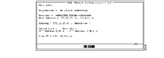
To access the information screen, select Info from the netconfig main menu. The info screen ( Figure 4-25) shows the date, the keyboard map, the network settings, and the serial settings. Changes made by netconfig are shown in this menu. However, they will be only activated after a system reboot. The header line shows the netconfig version in use. In case of trouble with the NEMI, you should make sure that you have the latest available version.
Figure 4-25 NEMI Network Configuration Screen
Restore Options
The netconfig main menu screen provides three options to restore the system to previously saved configurations:
•
•
•
Caution
NEMI 32 Channel Configuration
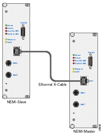
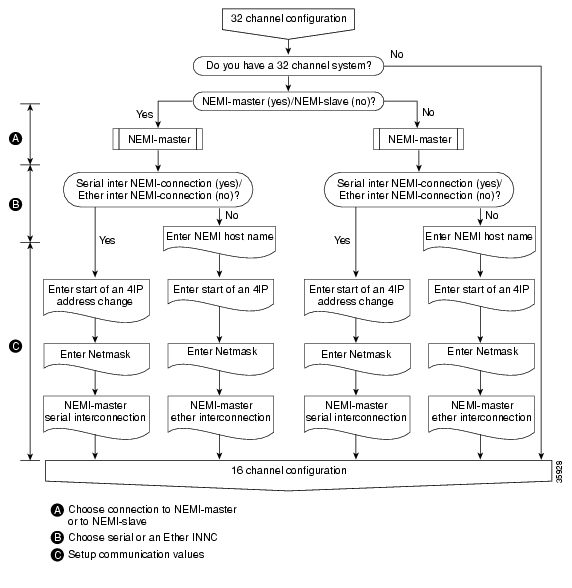
The 32 Channel system consists of two 16 Channel systems, which are interconnected using a hidden network domain between two NEMIs. The NEMI in the primary chassis is called the NEMI-Master and the NEMI in extension chassis B is called the NEMI-Slave. This type of configuration is called an Inter-NEMI Network Connection (INNC). Figure 4-26 shows the physical configuration of the Cisco Metro 1500 series 32 Channel system and Figure 4-27 shows the software configuration steps flowchart.
Figure 4-26 Cisco Metro 1500 Series 32 Channel System Configuration
Figure 4-27 Cisco Metro 1500 Series 32 Channel System Software Configuration Flowchart
The 32 Channel system can be configured in two different ways:
1.
2.
The Cisco Metro 1500 series leaves the factory configured as a 16 channel system. To configure a 32 Channel system you need to link two 16 Channel systems (each with a NEMI) together through either their ethernet ports (using an ethernet X-Cable) or by linking their serial ports using a LapLink cable.
Note
In a serial inter-connection, serial connections to both NEMIs are used for network management or service. In an Ethernet inter-connection, you can use the two free 10BaseT ports for these same tasks. The NEMI connected to the LAN is called the NEMI-Master and the NEMI used for service and configuration is called the NEMI-Slave.
The following configuration steps need to be repeated for both NEMIs:
1.
2.
After successful configuration and connection of both NEMIs, both systems exchange their data via the INNC and the same information is available on both systems. The two 16 channel systems that were separate, now appear to be a single 32 Channel system.
To achieve this task, the INNC needs a four address block of IP addresses out of a network address range. These addresses must not be used locally and cannot be routed.
Note
The /etc/.ResetNemiConfiguration file prepares the configuration process and reboots the NEMI. The netconfig option (after the reboot) displays the following screens, collects settings for the INNC and then branches into basic 16-channel netconfig mode.
To start the process, you need to login as root. After doing so, type the following:
/etc/.R<TAB><ENTER>Hitting the TAB-Key after the R invokes filename recognition and since there is only one filename, which starts with .R in the directory /etc, you will see the following:
/etc/.ResetNemiConfigThe Enter key starts execution of this program.
The ResetNEMIConfig file (as its name implies) resets the default 16 Channel configuration and allows you to define a new (in this case) 32 Channel configuration. This program reboots the NEMI. After the reboot, log in again as root and type the following:
netconfigThe first screen to appear is the NEMI Setup screen. See Figure 4-28. Select Yes to begin a 32 Channel configuration.
Figure 4-28 NEMI Setup Screen One
The next screen asks if you are working with a NEMI-Master or a NEMI-Slave. See Figure 4-29.
Figure 4-29 NEMI Setup Screen Two
You'll need to go through this sequence once while being logged in on the NEMI-Master and once again while being logged in on the NEMI-Slave.
Figure 4-30 NEMI 32 Channel Master Setup Screen One
At this stage you need to decide what type of INNC to use. It has to be the same type for both the NEMI-Master and NEMI-Slave. It can be either serial (as in this example), or 10BaseT.
Figure 4-31 NEMI 32 Channel Master Setup Screen Two
Next, enter the IP address range for the INNC. See Figure 4-32.
Figure 4-32 Enter NEMI 32 Channel Master Start of IP Address Screen
Record the block of IP addresses. They need to be the same for both the NEMI-Master and the NEMI-Slave. The program chooses the right address for each NEMI according to NEMI type. Next, enter the netmask of the NEMI. See Figure 4-33.
Figure 4-33 Enter NEMI Netmask
The NEMI 32 Channel Master Setup summary screen appears. See Figure 4-34. Look it over carefully and confirm your configuration options by selecting Yes.
Figure 4-34 NEMI 32 Channel Master Setup Summary Screen
You are now returned to the INNC netconfig menu screen. See Figure 4-35 and the "netconfig Command Options" section.
Figure 4-35 NEMI 32 Channel Master Serial Inter-Conn Setup Screen
These steps are the same as configuring a 16 Channel system. However, if the INNC uses the serial port, the serial menu entry is not displayed. Similarly, if the INNC uses the ethernet port, the Ethernet menu does not appear.
Software Maintenance Overview
The following sections provide information on various software maintenance issues that may arise while using the Cisco Metro 1500 series system.
Rebooting the NEMI
The NEMI may be rebooted using one of the following procedures:
1.
Log in using the root account and password. From the command line, issue the reboot command. This will result in an orderly shutdown and restart of the NEMI operating system. The optical systems are not affected by this type of reboot.
2.
The hardware reset button is recessed in a small hole located on the NEMI module just below the bus interconnect ports at the bottom of the NEMI module. Insert a small pointed object to depress the Reset button and reboot the NEMI. The optical systems are not affected by this type of reboot.
Emergency Password Reset
Security within the Linux operating system is robust. Since the Cisco Metro 1500 series system can supply a sizable portion of network bandwidth to the enterprise; security is a major concern. However, situations do arise when one of the access passwords to the system is not readily available, but access needs to be provided as soon as possible.
For these reasons, the system offers a password reset option that will return all passwords to their factory defaults.
To reset the factory passwords, follow these steps:
Step 1
Step 2
Step 3
account: Maintpassword: ChgMeNOWBe aware of upper and lower case sensitivity. Successful logging into the Maint account results in a pair of triple beeps and a reboot. Once rebooted, the system passwords are reset to their factory default values.
Password Reset Restrictions and Caveats
All logins are logged by the system. Restarts are also logged and transmitted using SNMP. The Maint account is only open for a window of 20 seconds after the last beep. Any attempt before or after that time will lead to standard UNIX procedures for handling wrong passwords or illegal logins (next login is delayed).
Therefore, you need to wait until the last beep to avoid system delays. It might take several attempts to complete this procedure. Only passwords are reset to factory defaults. All other settings and performance of the optical transmission systems are unaffected. This procedure does not interrupt optical traffic.
Cisco recommends that you personalize the NEMI passwords as soon as possible to minimize possible exposure. This is true even if the endpoints of the optical network are within the physical security zone. You want to restrict access to the NEMI to keep system security (and thereby system stability) high.
Software Updates
See the "Downloading a System Update" section on page C-1 for information on downloading and installing system software upgrades as they become available.
![]()
![]()
![]()
![]()
![]()
![]()
![]()
![]()
Posted: Tue Apr 26 06:01:01 PDT 2005
All contents are Copyright © 1992--2005 Cisco Systems, Inc. All rights reserved.
Important Notices and Privacy Statement.