|
|

Table Of Contents
Cisco Metro 1500 Series Spares Installation Note
Installing, Removing, and Cabling Modules
Removing and Installing the Power Supply Module
Replacing a Power Supply Module
Safety Information Referral Warning
Obtaining Technical Assistance
Cisco Metro 1500 Series Spares Installation Note
This installation note describes how to install and configure the spares for the Cisco Metro 1500 series metropolitan area network (MAN) dense wavelength division multiplexing (DWDM) system.
For a complete description of the commands to configure and maintain the Cisco Metro 1500 series system, refer to the Cisco Metro 1500 Series Management Guide. For complete Cisco Metro 1500 series installation information, refer to the Cisco Metro 1500 Series Operations Guide. The documents are available on the Documentation CD-ROM, the World Wide Web, or in print.
Contents
This document contains the following sections:
•
Installing, Removing, and Cabling Modules
•
•
Installing, Removing, and Cabling Modules
This section describes installing, removing, and cabling modules in the chassis. The following modules are covered:
•
•
•
•
•
•
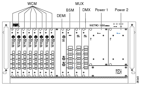
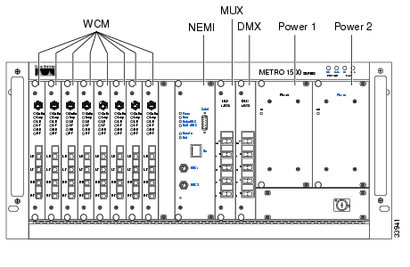
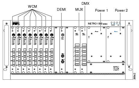
Refer to Figure 1, Figure 2, Figure 3, and Figure 4 for specific module slot locations.
Figure 1 Primary Chassis, Front View
Figure 2 Extension Chassis A, Front View
Figure 3 Extension Chassis B, Front View
Figure 4 Extension Chassis C, Front View
Required Tools
The following tools are required for installing modules in the chassis:
•
•
•
Warning
Installing a Module
You can add a module to your system without interrupting unit operation.
Note
Warning
To install a module, complete these steps:
Step 1
Step 2
Step 3
Step 4
Caution
Step 5
Step 6
Removing a Module
To remove a module from the Cisco Metro 1500 series unit without interrupting unit operation, complete these steps:
Warning
Step 1
Step 2
Step 3
Step 4
Step 5
Step 6
Step 7
Cabling a Module
After you have installed the module, you are ready to cable it. Refer to the Cisco Metro 1500 Series Operations Guide for instructions on cabling the different types of modules.
Cleaning Optical Connectors
The ferrules and end-face surfaces of fiber components must be kept clean and free of contaminants. To clean the connectors and loop plugs, complete these steps:
Step 1
Step 2
Step 3
If the surface is not clean or does not have a uniform shine, repeat the process using a fresh surface of the alcohol pad.
Caution
Removing and Installing the Power Supply Module
This section covers the removal and replacement of the power supply module (PSM).
Warning
The Cisco Metro 1500 series system has two identical, fully redundant PSMs. Each PSM can take over the power needs of the entire system.These PSMs provide 5V and 30A to the system, as well as full input-to-output, input-to-case, and output-to-output isolation.
Powering On and Off
Caution
Turn the power on or off using the key switch (refer to Figure 5). This switch supplies power to the redundant power supplies. You can only move the switch to on or off. Two keys are shipped with each unit and all units use the same key. The key can be removed in either the 1 or 0 position.
The status of power on and off is indicated on the display panel in front of the chassis and can be observed using network management at the NEMI. Refer to the Cisco Metro 1500 Series Management Guide for more information about power supply observation using network management and the NEMI.
Replacing a Power Supply Module
If the green LED on a power supply is off while the unit is powered on, and the power cable is plugged in the corresponding power socket, either the cable is faulty or the power supply itself has failed. First, check the power cable to make sure that it is securely plugged into the unit. If the cable is correctly attached, replace the power supply. During this procedure, the system will keep running with its remaining power supply. The redundant power supply continues to provide uninterrupted service but you should check and replace the failed unit as soon as possible.
Note
Figure 5 Power Suppliy Modules (PSMs)
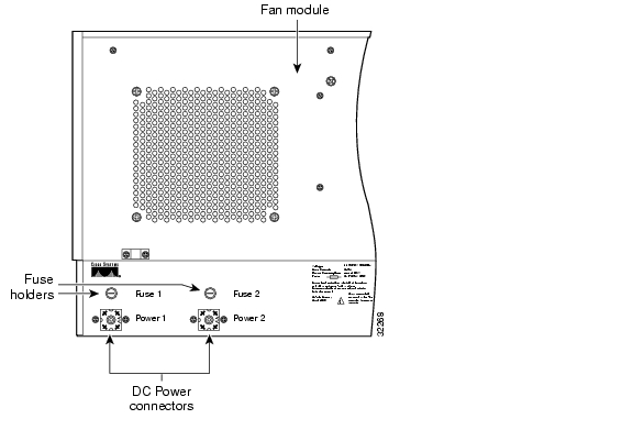
Figure 6 Rear View of Power Supply Module
All PSMs are hot-swappable and can be replaced while the system is in service. To replace a PSM, complete these steps:
Step 1
Step 2
Step 3
Step 4
Step 5
Step 6
Translated Warnings
This section repeats in multiple languages the warnings in this note. These translated warnings can be used with other documents related to this note.
Installation Warning
Safety Information Referral Warning
Obtaining Documentation
World Wide Web
You can access the most current Cisco documentation on the World Wide Web at http://www.cisco.com, http://www-china.cisco.com, or http://www-europe.cisco.com.
Documentation CD-ROM
Cisco documentation and additional literature are available in a CD-ROM package, which ships with your product. The Documentation CD-ROM is updated monthly. Therefore, it is probably more current than printed documentation. The CD-ROM package is available as a single unit or as an annual subscription.
Ordering Documentation
Registered CCO users can order the Documentation CD-ROM and other Cisco Product documentation through our online Subscription Services at http://www.cisco.com/cgi-bin/subcat/kaojump.cgi.
Nonregistered CCO users can order documentation through a local account representative by calling Cisco's corporate headquarters (California, USA) at 408 526-4000 or, in North America, call 800 553-NETS (6387).
Obtaining Technical Assistance
Cisco provides Cisco Connection Online (CCO) as a starting point for all technical assistance. Warranty or maintenance contract customers can use the Technical Assistance Center. All customers can submit technical feedback on Cisco documentation using the web, e-mail, a self-addressed stamped response card included in many printed docs, or by sending mail to Cisco.
Cisco Connection Online
Cisco continues to revolutionize how business is done on the Internet. Cisco Connection Online is the foundation of a suite of interactive, networked services that provides immediate, open access to Cisco information and resources at anytime, from anywhere in the world. This highly integrated Internet application is a powerful, easy-to-use tool for doing business with Cisco.
CCO's broad range of features and services helps customers and partners to streamline business processes and improve productivity. Through CCO, you will find information about Cisco and our networking solutions, services, and programs. In addition, you can resolve technical issues with online support services, download and test software packages, and order Cisco learning materials and merchandise. Valuable online skill assessment, training, and certification programs are also available.
Customers and partners can self-register on CCO to obtain additional personalized information and services. Registered users may order products, check on the status of an order and view benefits specific to their relationships with Cisco.
You can access CCO in the following ways:
•
•
•
–
–
You can e-mail questions about using CCO to cco-team@cisco.com.
Technical Assistance Center
The Cisco Technical Assistance Center (TAC) is available to warranty or maintenance contract customers who need technical assistance with a Cisco product that is under warranty or covered by a maintenance contract.
To display the TAC web site that includes links to technical support information and software upgrades and for requesting TAC support, use www.cisco.com/techsupport.
To contact by e-mail, use one of the following:
In North America, TAC can be reached at 800 553-2447 or 408 526-7209. For other telephone numbers and TAC e-mail addresses worldwide, consult the following web site: http://www.cisco.com/warp/public/687/Directory/DirTAC.shtml.
Documentation Feedback
If you are reading Cisco product documentation on the World Wide Web, you can submit technical comments electronically. Click Feedback in the toolbar and select Documentation. After you complete the form, click Submit to send it to Cisco.
You can e-mail your comments to bug-doc@cisco.com.
To submit your comments by mail, for your convenience many documents contain a response card behind the front cover. Otherwise, you can mail your comments to the following address:
Cisco Systems, Inc.
Document Resource Connection
170 West Tasman Drive
San Jose, CA 95134-9883We appreciate and value your comments
This document is to be used in conjunction with the Cisco Metro 1500 Series Operations Guide.
Access Registrar, AccessPath, Any to Any, Are You Ready, AtmDirector, Browse with Me, CCDA, CCDE, CCDP, CCIE, CCNA, CCNP, CCSI, CD-PAC, the Cisco logo, Cisco Certified Internetwork Expert logo, CiscoLink, the Cisco Management Connection logo, the Cisco NetWorks logo, the Cisco Powered Network logo, Cisco Systems Capital, the Cisco Systems Capital logo, Cisco Systems Networking Academy, the Cisco Systems Networking Academy logo, the Cisco Technologies logo, Fast Step, FireRunner, Follow Me Browsing, FormShare, GigaStack, IGX, Intelligence in the Optical Core, Internet Quotient, IP/VC, IQ Breakthrough, IQ Expertise, IQ FastTrack, IQ Readiness Scorecard, The IQ Logo, Kernel Proxy, MGX, Natural Network Viewer, NetSonar, Network Registrar, the Networkers logo, Packet, PIX, Point and Click Internetworking, Policy Builder, Precept, RateMUX, ReyMaster, ReyView, ScriptShare, Secure Script, Shop with Me, SlideCast, SMARTnet, SVX, The Cell, TrafficDirector, TransPath, VlanDirector, Voice LAN, Wavelength Router, Workgroup Director, and Workgroup Stack are trademarks; Changing the Way We Work, Live, Play, and Learn, Empowering the Internet Generation, The Internet Economy, and The New Internet Economy are service marks; and Aironet, ASIST, BPX, Catalyst, Cisco, Cisco IOS, the Cisco IOS logo, Cisco Systems, the Cisco Systems logo, the Cisco Systems Cisco Press logo, CollisionFree, Enterprise/Solver, EtherChannel, EtherSwitch, FastHub, FastLink, FastPAD, FastSwitch, GeoTel, IOS, IP/TV, IPX, LightStream, LightSwitch, MICA, NetRanger, Post-Routing, Pre-Routing, Registrar, StrataView Plus, Stratm, TeleRouter, and VCO are registered trademarks of Cisco Systems, Inc. or its affiliates in the U.S. and certain other countries. All other trademarks mentioned in this document are the property of their respective owners. The use of the word partner does not imply a partnership relationship between Cisco and any other company. (0005R)
Copyright © 2000, Cisco Systems, Inc.
All rights reserved.
![]()
![]()
![]()
![]()
![]()
![]()
![]()
![]()
Posted: Thu Aug 30 06:42:02 PDT 2007
All contents are Copyright © 1992--2007 Cisco Systems, Inc. All rights reserved.
Important Notices and Privacy Statement.