|
|

Table Of Contents
Troubleshooting Mux/Demux Module Problems
3.2 Initial Troubleshooting Checklist
3.3 Troubleshooting Mux/Demux Module Interface Problems
3.3.2 Mux/Demux Module Is Not Recognized
3.3.3 Mux/Demux Filter Interfaces Are Not Recognized After a Processor Card Switchover
3.3.4 Mux/Demux Traffic Degrades or Fails
Troubleshooting Mux/Demux Module Problems
This chapter describes how to troubleshoot mux/demux module problems. This chapter contains the following sections:
•
Overview
•
•
3.1 Overview
The optical mux/demux motherboards occupy slots 0 and 1 of the Cisco ONS 15540 ESPx chassis. The chassis uses one optical mux/demux motherboard for unprotected operation or two per system for protected operation. The chassis supports the following mux/demux motherboards:
•
•
Each Cisco ONS 15540 ESPx mux/demux motherboard can accept up to four 4-channel or 8-channel mux/demux modules or one 32-channel mux/demux module. The modular mux/demux motherboards are available with or without OSC (optical supervisory channel) and can be populated according to user needs.
There are three types of mux/demux modules available:
•
•
•
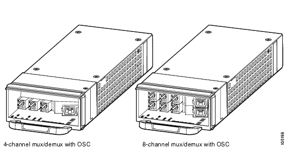
Channels not filtered are passed on to the next mux/demux module. (See Figure 3-1.)
Figure 3-1 4- and 8-Channel Mux/Demux Modules with OSC
One 32-channel terminal mux/demux module can be installed in slot 0 or 1 of the Cisco ONS 15540 ESPx chassis. The 32-channel terminal mux/demux module is equipped with OSC, input/output, and monitoring ports that use MU connectors. The remaining 8 ports that connect to the transponder modules use MTP connectors. The OSC is a dedicated, full duplex communication ITU-T DWDM channel for in-band management traffic. The input/output ports are trunk connections used to connect to the external fiber trunks. Monitoring ports use a one percent tap coupler (20 dB) for both the mux and demux sides and also allow you to non-obtrusively connect an OSA (optical spectrum analyzer) to monitor the incoming or outgoing DWDM signals.
3.2 Initial Troubleshooting Checklist
Follow this initial checklist before proceeding with the troubleshooting procedures:
•
•
•
3.3 Troubleshooting Mux/Demux Module Interface Problems
This section contains troubleshooting procedures for mux/demux module interface problems.
3.3.1 OSC Wave Interface Down
Symptom The OSC wave interface is down.
Table 3-1 describes the potential causes of the symptom and the solutions.
3.3.2 Mux/Demux Module Is Not Recognized
Symptom The mux/demux module does not appear in the show interfaces or the show running-config command output.
Table 3-2 describes the potential cause of the symptom and the solution.
3.3.3 Mux/Demux Filter Interfaces Are Not Recognized After a Processor Card Switchover
Symptom Mux/demux filter interfaces are not recognized after a processor card switchover.
Table 3-3 describes the potential cause of the symptom and the solution.
3.3.4 Mux/Demux Traffic Degrades or Fails
Symptom Mux/demux traffic degrades or fails.
Table 3-4 describes the potential cause of the symptom and the solution.
Table 3-4 Mux/Demux Traffic Degrades or Fails
CPU power loss. Both CPUs are down. A power failure significantly reduces the power at the receiver because the passband of the arrayed wavelength grating (AWG) filter is temperature sensitive.
Investigate the CPU power failure. For more information on CPU troubleshooting, see Chapter 2, "Troubleshooting Processor Card Problems."
![]()
![]()
![]()
![]()
![]()
![]()
![]()
![]()
Posted: Thu Feb 16 04:57:58 PST 2006
All contents are Copyright © 1992--2006 Cisco Systems, Inc. All rights reserved.
Important Notices and Privacy Statement.