|
|

Table Of Contents
Shelf Rules for Mux/Demux Motherboards
Shelf Rules for 4-Channel and 8-Channel Add/Drop Mux/Demux Modules
Add/Drop Mux/Demux Modules Without Protection
Add/Drop Mux/Demux Modules with Protection
Cabling Add/Drop Mux/Demux Modules
Shelf Rules for 32-Channel Terminal Mux/Demux Modules
Shelf Rules for Transponder Modules
Shelf Rules for Line Card Motherboards
Rules for Configurations with 10-Gbps Line Card Motherboards
Rules for Protected Configurations
Cabling Line Card Motherboards to the Mux/Demux Modules
Cabling Rules for Cross Connect Drawers
General Rules for Ring Topologies
Shelf Configuration Rules
The design of the Cisco ONS 15540 ESPx requires that a set of rules be followed during physical configuration of the shelf. These rules, along with examples, are provided in this chapter. This chapter contains the following major sections:
•
Shelf Rules for Mux/Demux Motherboards
•
•
•
•
•
•
Note
Shelf Rules for Mux/Demux Motherboards
This section describes the shelf rules for mux/demux motherboards.
OSC Support
In configurations where the OSC is not used, only one mux/demux motherboard is required on the shelf. When the OSC is used, two mux/demux motherboards with OSC support are required on the shelf.
Shelf Rules for 4-Channel and 8-Channel Add/Drop Mux/Demux Modules
This section describes the shelf rules for 4-channel and 8-channel add/drop mux/demux modules for different types of protection.
Add/Drop Mux/Demux Modules Without Protection
In an unprotected configuration, a shelf can have only one 4-channel or 8-channel add/drop mux/demux module with a given channel band transmitting and receiving in a given direction (either west or east). Table 3-1 lists the conflicting bands 4-channel and 8-channel add/drop mux/demux modules. If an add/drop mux/demux module that supports a band in a particular row of column 1 in Table 3-1 is installed on a shelf in an unprotected configuration, that shelf cannot also have a module that supports any of the conflicting bands in column 2 transmitting and receiving in the same direction. For example, modules for band A and band AB both cannot transmit to and receive from the west.
Add/Drop Mux/Demux Modules with Protection
When configuring channels to use splitter protection or line card protection, two 4-channel or 8-channel add/drop mux/demux modules with the same channels must be present on the shelf. Table 3-1 lists the conflicting bands when using the 4-channel or 8-channel add/drop mux/demux modules. If two add/drop mux/demux modules that support a band in a particular row of column 1 in Table 3-1 are installed on a shelf in an unprotected configuration, that shelf cannot also have other mux/demux modules that support any of the conflicting bands in column 2. For example, if the two mux/demux modules support band A, then there can be no mux/demux modules supporting band AB on the same shelf.
Note
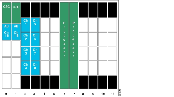
Figure 3-1 shows an example shelf configuration for splitter protection with add/drop mux/demux modules for band AB in positions 0/0 and 1/0.
Figure 3-1 Example Installation of Add/Drop Mux/Demux Modules with Splitter Protection
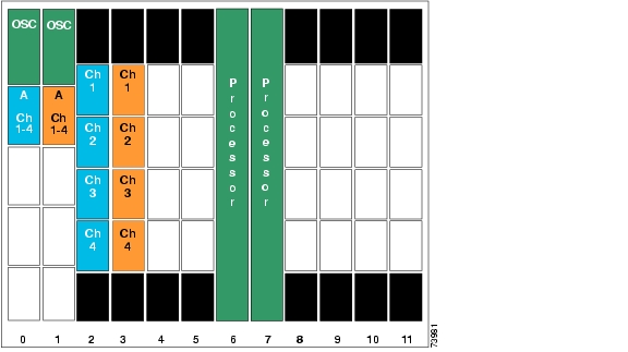
Figure 3-2 shows an example shelf configuration for line card protection with add/drop mux/demux modules for band A in positions 0/0 and 1/0.
Figure 3-2 Example Installation of Add/Drop Mux/Demux Modules with Line Card Protection
Cabling Add/Drop Mux/Demux Modules
The following rules apply when cabling the trunk and thru interfaces on the 4-channel and 8-channel add/drop mux/demux modules:
•
•
•
•
•
•
For examples of cabling add/drop mux/demux module in a protected ring configuration, see Figure 1-7 on page 1-17 and Figure 1-8 on page 1-18.
Shelf Rules for 32-Channel Terminal Mux/Demux Modules
The following rules apply when cabling the 32-channel terminal mux/demux modules:
•
•
Shelf Rules for Transponder Modules
The following rules apply to transponder modules:
•
•
•
Table 3-2 Transponder Module Placement When Using Direct Cross Connects
w+0
y/0
w+1
y/1
w+2
y/2
w+3
y/3
1 w = first channel number in a 4-channel band
2 y = transponder slot number in the shelf
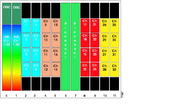
See Figure 3-3 for an example configuration.
Note
Figure 3-3 Example Shelf Configuration Using 32-Channel Terminal Mux/Demux Modules
Shelf Rules for Line Card Motherboards
The line card motherboards have MTP connectors located on their front panels: one connector on unprotected motherboards and two connectors for splitter protected motherboards.
In 2.5-Gbps line card motherboards, each MTP connector supports one 4-channel band. In 10-Gbps line card motherboards, each MTP connector supports one 1-channel band.
Line card motherboards can only install into slots 2 through 5 and slots 8 through 11.
Rules for Configurations with 10-Gbps Line Card Motherboards
An unprotected configuration of 10-Gbps line card motherboards with 10-GE transponder modules supports 16 channels. A protected configuration supports 8 channels.
Rules for Protected Configurations
The rules for line card motherboards in protected configurations are as follows:
•
•
•
Note
Cabling Line Card Motherboards to the Mux/Demux Modules
The Cisco ONS 15540 ESPx supports mux/demux modules with front panel optical filter connectors. If all channels in the line card motherboard are added and dropped at the node, cross connect the line card motherboard MTP connector directly to the mux/demux module. Each mux/demux module supports a specific band of channels. Every 4-channel band on the mux/demux module has its own MTP connector. A 4-channel mux/demux module has one MTP connector, an 8-channels has two, and a 32-channel mux/demux module has eight. Always connect the line card motherboard to the MTP connector for the channels supported by the transponders in the line card motherboard.
Shelf Rules for PSMs
For trunk fiber protection to function when the PSM (protection switch module) connects to a mux/demux module, the OSC or the in-band message channel (or both) must be available on the shelf. If the OSC is present, the PSM must connect to the mux/demux module that supports the OSC. If the PSM connects to a 10-GE transponder module, use the in-band message channel as the APS message channel to support trunk fiber protection. If the PSM connects to a 2.5-Gbps transponder module, use IP for the APS message channel.
Cabling Rules for Cross Connect Drawers
The optical cross connect drawer provides a much greater degree of flexibility for provisioning channels on the Cisco ONS 15540 ESPx. It allows you access to individual channels within a band. You can, for example, pass through some channels within a band while adding and dropping others. The cross connect drawer also allows the Cisco ONS 15540 ESPx to accept ITU grid signals from other platforms, such as the Cisco ONS 15530.
For protected configurations, a cross connect drawer supports up to 16 channels. To support more than 8 protected channels, use two cross connect drawers.
Note
General Rules for Ring Topologies
The following network rules apply to ring topologies:
•
•
•
![]()
![]()
![]()
![]()
![]()
![]()
![]()
![]()
Posted: Tue Jan 25 15:02:05 PST 2005
All contents are Copyright © 1992--2005 Cisco Systems, Inc. All rights reserved.
Important Notices and Privacy Statement.