|
|

Table Of Contents
10-Gigabit Ethernet Functionality
2.5-Gbps Line Card Motherboards
10-Gbps Line Card Motherboards
Comparison of In-Band Message Channel, SONET, and OSC
System Overview
The Cisco ONS 15540 ESPx is an optical transport platform that employs DWDM (dense wavelength division multiplexing) technology. With the Cisco ONS 15540 ESPx, users can take advantage of the availability of dark fiber to build a common infrastructure that supports data networking (Ethernet based as well as SONET/SDH based) and storage networking.
This chapter contains the following major sections:
•
System and Network Management
Chassis Description
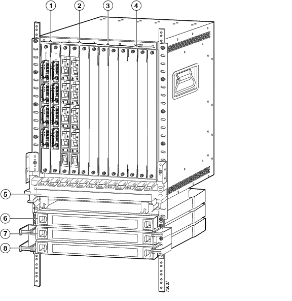
The Cisco ONS 15540 ESPx uses a 12-slot modular vertical chassis (see Figure 1-1). The system receives power through redundant -48 VDC inputs. A redundant external AC power supply is available, or DC power can be provided directly. As you face the chassis, the two leftmost slots (slots 0 and 1) hold the mux/demux motherboards. These slots, which are populated with optical mux/demux modules, correspond to the west and east directions, respectively. Slot 0 or 1 can also contain a PSM (protection switch module) to provide trunk fiber protection switch. Slots 2 to 5 and 8 to 11 hold the line card motherboards, which are populated with transponder modules. Slots 6 and 7 hold the processor cards. Air inlet, fan tray, and cable management are located beneath the modular slots. The system has an electrical backplane for system control.
Figure 1-1 Cisco ONS 15540 ESPx Shelf Layout
System Functional Overview
The Cisco ONS 15540 ESPx connects to client equipment to the DWDM trunk (transport network). Simply described, the Cisco ONS 15540 ESPx takes a client signal and converts it to an ITU-T G.692 compliant wavelength, then optically multiplexes it with the other client signals for transmission over an optical fiber link.
The Cisco ONS 15540 ESPx supports 1+1 path protection using both hardware and software mechanisms. In a single shelf configuration, a Cisco ONS 15540 ESPx node can support up to 32 channels with facility (fiber) protection or 16 channels with line card protection. In a dual shelf configuration a node can support up to 32 channels with line card protection.
The Cisco ONS 15540 ESPx can be deployed in point-to-point, linear add/drop, hubbed ring, and meshed ring topologies. Mulitple trunks connected to a single shelf can support two or more of these topologies.
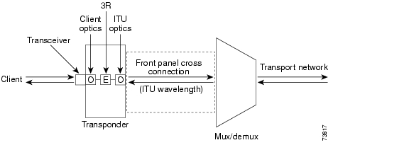
The transponder module receives the client signal through a transceiver attached to the external port. Inside the transponder module the 850-nm or 1310-nm input optical signal is converted to an electrical signal and the 3R (reshape, retime, retransmit) function is performed. A modulated laser diode then converts the electrical signal back to an optical one with a specific wavelength that complies with the ITU laser grid.
Inside the optical mux/demux module the input signals are multiplexed into a single DWDM signal and launched into the fiber on the trunk side. Thus, a one-to-one relationship exists between each client signal and each wavelength on the trunk side.
The Cisco ONS 15540 ESPx is a duplex system with both light emitters for transmission and light detectors for reception. For example, the client side interfaces on the transponder modules both transmit and receive light. The same is true of the transponder's DWDM interface. Also, the optical mux/demux modules both multiplex the transmit signal and demultiplex the receive signal.
Figure 1-2 illustrates the principal functions involved in transmission of the signal between the client and trunk networks within the Cisco ONS 15540 ESPx. The optical signal leaves the transponder module and travels from the backplane side of the transponder module to an optical connector on the front panel of the line card motherboard. Optical cross connections from the front panel of the line card motherboard take the signal to the mux/demux modules.
Figure 1-2 Simplified Data Flow Architecture for the Cisco ONS 15540 ESPx
10-Gigabit Ethernet Functionality
The 10-GE transponder module transports 10-Gigabit Ethernet over the network. The module can be used as a downlink to the Cisco ONS 15530 and for direct connections to 10-GE interfaces on client equipment.
The hardware providing this functionality includes a 10-Gbps line card motherboard and 10-GE transponder modules.
System Components
The Cisco ONS 15540 ESPx has a modular architecture that allows flexibility in configuration and permits incremental upgrades of the system. These components are described in the following sections.
Transponder Modules
The Cisco ONS 15540 ESPx supports four types of transponder modules: Type 1 SM (single-mode), Type 1 MM (multimode), Type 2 extended range with SFP optics, and 10 GE.
The transponder modules populate the line card motherboards and have two interfaces: an external interface that connects to client equipment, and an internal interface that connects to the line card motherboard.
In the transponder module, the client signal is regenerated and retransmitted on an ITU-compliant wavelength.
The laser on each 2.5-Gbps transponder module is capable of generating one of two wavelengths on the trunk side. Thus, 16 different transponder modules exist (for channels 1-2, 3-4,..., 31-32) to support the 32 channels; each module is available in Type 1 SM, Type 1 MM, and Type 2 extended range versions. The wavelength the module generates is configurable from the CLI (command-line interface).
The 10-GE transponder modules each support one wavelength on the trunk side for a total of 32 different transponder modules.
A safety protocol, LSC (laser safety control), shuts the transmit laser down on the trunk side when a fiber break or removed connector is detected. The transponder modules are hot pluggable, permitting in-service upgrades and replacement.
Type 1 SM Transponder Modules and MM Transponder Modules
The SM transponder modules and MM transponder modules are Type 1 transponder modules with fixed, nonpluggable client interface ports. The client interfaces are protocol transparent and bit-rate transparent, and accept either single-mode or multimode client signals on the 1310-nm wavelength through SC connectors. The multimode transponder supports 62.5 Βm MM, 50 Βm MM, and 9 or 10 Βm SM fiber; the single-mode transponder supports 50 Βm MM fiber and 9 or 10 Βm SM fiber.
The transponder client interfaces support encapsulation of client signals in either 3R enhanced mode, which allows some client protocol monitoring (such as code violations and data errors) or regular 3R mode, where the transponder is transparent to the client data stream. In either case, the content of the client data stream remains unmodified. Configurable failure and degrade thresholds for monitored protocols are also supported.
Table 1-1 shows the common client signal encapsulations supported on the SM transponder modules and MM transponder modules.
Table 1-2 shows the IBM storage protocols on the SM transponder modules and MM transponder modules.
Table 1-2 IBM Storage Protocols Supported on Single-Mode and Multimode Transponder Modules
Encapsulation
MonitoringESCON (200 Mbps)
SM 9 or 10/125 Βm
Yes
No
Yes
Yes
Yes
MM 50/125 Βm
Yes
No
No
Yes
Yes
MM 62.5/125 Βm
Yes
No
No
Yes
Yes
FICON (1062 Mbps)
SM 9 or 10/125 Βm
Yes
No
Yes
No
Yes
MM 50/125 Βm
Yes
No
Yes1
No
Yes
MM 62.5/125 Βm
Yes
No
Yes 1
No
Yes
FICON (2125 Mbps)
SM 9 or 10/125 Βm
Yes
No
Yes
No
Yes
MM 50/125 Βm
Yes
No
Yes2
No
Yes
MM 62.5/125 Βm
Yes
No
Yes 1
No
Yes
Coupling Facility,
ISC compatibility
(1062 Mbps)SM 9 or 10/125 Βm
Yes
No
Yes
No
Yes
MM 50/125 Βm
Yes
No
Yes 1
No
Yes
MM 62.5/125 Βm
No
No
—
—
—
Coupling Facility,
ISC peer (2125 Mbps)SM 9 or 10/125 Βm
Yes
No
Yes
No
Yes
MM 50/125 Βm
No
No
—
—
—
MM 62.5/125 Βm
No
No
—
—
—
Coupling Facility,
ISC peer (1062 Mbps)SM 9 or 10/125 Βm
Yes
No
Yes
No
Yes
MM 50/125 Βm
No
No
—
—
—
MM 62.5/125 Βm
No
No
—
—
—
Sysplex Timer (ETR and CLO)
(8 Mbps3 )SM 9 or 10/125 Βm
No
No
—
—
—
MM 50/125 Βm
Yes
No
No
Yes
No
MM 62.5/125 Βm
Yes
No
No
Yes
No
1 These protocols require the use of a special mode-conditioning patch cable (available from IBM) at each end of the connection.
2 These protocols require the use of a special mode-conditioning patch cable (available from IBM) at each end of the connection.
3 Sysplex Timer is the only protocol supported at a clock rate less than 16 Mbps.
Table 1-3 shows some other common protocols that are supported on the SM transponder modules and MM transponder modules without protocol monitoring.
Additional discrete rates are also supported in regular 3R mode. For SM transponder modules, these rates fall between 16 Mbps and 2.5 Gbps; for MM transponder modules, the rates are between 16 Mbps and 622 Mbps.
Note
The system supports OFC (open fiber control) for Fibre Channel and ISC encapsulations. Alternatively, FLC (forward laser control) can be enabled to shut down the laser on the client or trunk side if a LOL (loss of light) is detected on the other side.
Note
For detailed information about client interface configuration, refer to the Cisco ONS 15540 ESPx Configuration Guide.
Type 2 Extended Range Transponder Modules with SFP Optics
The Type 2 extended range transponder module accepts two types of SFP optics:
•
•
Fixed rate SFP optics modules support specific protocols. Table 1-4 lists the features for the fixed rate SFP optics supported by the Type 2 extended range transponder modules.
Table 1-4 Fixed Rate SFP Optics Features
15500-XVRA-01A2
ESCON, SONET OC-3 SR, SDH STM-1
MM 50/125 Βm
MM 62.5/125 Βm1310 nm
MT-RJ
15500-XVRA-02C1
Gigabit Ethernet1 ,
Fibre Channel (1 Gbps)2 , FICON (1 Gbps), ISC-1 (1-Gbps)MM 50/125 Βm
MM 62.5/125 Βm850 nm
LC
15500-SFP-GEFC-SX
Fibre Channel (1 Gbps and 2 Gbps)3 , FICON (1 Gbps and 2 Gbps), ISC-3 (1-Gbps and 2-Gbps), Gigabit Ethernet
MM 50/125 Βm
MM 62.5/125 Βm850 nm
LC
15500-XVRA-03B1
Gigabit Ethernet4 ,
Fibre Channel (1 Gbps)5 ,
FICON (1 Gbps), ISC compatibility mode (1 Gbps), ISC peer mode (1 Gbps)SM 9/125 Βm
1310 nm
LC
15500-XVRA-03B2
Fibre Channel (1 Gbps6 and 2 Gbps7 ), FICON (1 Gbps and 2 Gbps), ISC compatibility mode (1 Gbps), ISC peer mode (1 Gbps and 2 Gbps)
SM 9/125 Βm
1310 nm
LC
15500-XVRA-06B1
SONET OC-12 SR8 , SDH STM-4
SM 9/125 Βm
1310 nm
LC
15500-XVRA-07B1
SONET OC-48 SR, SDH STM-16
SM 9/125 Βm
1310 nm
LC
1 1000BASE-SX
2 FC-0-100-M5-SN-S and FC-0-100-M6-SN-S standards
3 FC-0-200-M5-SN-S and FC-0-200-M6-SN-S standards
4 1000BASE-LX
5 FC-0-100-SM-LC-S standard
6 FC-0-100-SM-LC-S standard
7 FC-0-200-SM-LC-S standard
8 SR = short range
Variable rate SPF optics modules support a range of clock rates. Table 1-5 lists features for the variable rate SFP optics supported by the Type 2 extended range transponder modules.
Table 1-5 Variable Rate SFP Optics Features
15500-XVRA-10A1
Low-band 8 Mbps to 200 Mbps
Sysplex (CLO and ETR)1 (8 Mbps),
Fast Ethernet2 (125 Mbps),
SONET OC-33 (155.52 Mbps),
SDH STM-1 (622 Mbps),
ESCON4 (200 Mbps)MM 50/125 Βm 62.5/125 Βm
1310 nm
LC
15500-XVRA-10B1
Low-band 8 Mbps to 200 Mbps
Sysplex (CLO and ETR)1 (8 Mbps),
Fast Ethernet2 (125 Mbps),
SONET OC-33 (155.52 Mbps),
SDH STM-1 (155.52 Mbps), ESCON4 (200 Mbps)SM 9/125 Βm
1310 nm
LC
15500-XVRA-11A1
Mid-band 200 Mbps to 622 Mbps
ESCON4 (200 Mbps),
SONET OC-123 (622 Mbps),
SDH STM-4 (622 Mbps)MM 50/125 Βm 62.5/125 Βm
1310 nm
LC
15500-XVRA-11B1
Mid-band 200 Mbps to 1.25 Gbps
ESCON4 (200 Mbps),
SONET OC-123 (622 Mbps),
SDH STM-4 (622 Mbps),
FC4 (1.062 Gbps),
FICON (1.062 Gbps),
GE4 (LX) (1.250 Gbps)
ISC compatibility mode (1.062 Gbps),
ISC peer mode (1.062 Gbps)SM 9/125 Βm
1310 nm
LC
15500-XVRA-12B1
High-band 1.062 Gbps to 2.488 Gbps
FC4 (1.062 Gbps and 2.125 Gbps),
FICON (1.062 Gbps and 2.125 Gbps),
GE4 (LX) (1.250 Mbps),
SONET OC-48 (2.488 Gbps),
SDH STM-16 (2.488 Gbps),
ISC compatibility mode (1.062 Gbps),
ISC peer mode (1.062 Gbps and 2.125 Gbps)SM 9/125 Βm
1310 nm
LC
1 Manchester coded
2 4B/5B coded
3 Scrambler 223-1
4 8B/10B coded
Note
The following protocols can be monitored with the Type 2 extended range transponder modules:
•
•
•
•
•
•
•
•
For detailed information about client interface configuration, refer to the Cisco ONS 15540 ESPx Configuration Guide.
Caution
For information on transceiver specifications, refer to the Cisco ONS 15540 ESPx Hardware Installation Guide.
The Type 2 extended range transponder modules also support the OFC (open fiber control) safety protocol for Fibre Channel.
Note
Conditions Monitored on 2.5-Gbps Transponder Modules
For GE, FC, and FICON traffic, the Cisco ONS 15540 ESPx monitors the following conditions:
•
•
•
•
For SONET errors, the Cisco ONS 15540 ESPx monitors the SONET section overhead only, not the SONET line overhead. Specifically, the Cisco ONS 15540 ESPx monitors the B1 byte and the framing bytes. The system can detect the following defect conditions:
•
•
•
•
For SONET performance, the system monitors the B1 byte, which is used to compute the four SONET section layer performance monitor parameters:
•
•
•
•
For ISC traffic, the system monitors the following conditions:
•
•
•
10-GE Transparent Transponder Modules
The 10-GE transponder module is double the size of the 2.5-Gbps transponder module and requires a special 10-Gbps line card motherboard. Network configurations that use 10-GE transponder might require Cisco ONS 15216 Dispersion Compensator Units.
Note
Each 10-GE transponder module supports one client side and one trunk side interface. The client side is a short-reach 1310 nm interface and the trunk side interface is an ITU grid compliant 15xx nm long-reach interface. The transmitter supports a 1260 nm to 1355 nm wavelength range. The 10-GE transponder module is available in 32 versions, one for each of the 32 ITU wavelengths.
The 10-GE transponder module is not protocol independent. It supports the IEEE 802.ae specification for 10GBASE-LR interfaces.
10-GE Transponder Module Performance Monitoring
This section describes the parameters, alarms and statistics that the 10-GE transponder module monitor.
The module monitors the following optical parameters:
•
•
The module monitors the following digital or protocol alarms:
•
•
•
•
The module collects the following statistics:
•
•
•
•
•
•
2.5-Gbps Line Card Motherboards
The 2.5Gbps line card motherboards hold the 2.5-Gbps transponder modules and provide front panel optical connectors for the ITU signal generated by the transponder modules. The 2.5-Gbps line card motherboards are modular and can be populated according to user needs. A single system can hold up to eight line card motherboards, each of which accepts four 2.5-Gbps transponder modules.
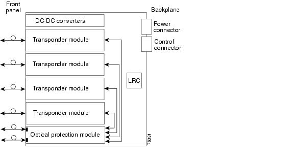
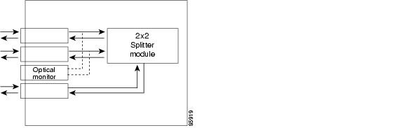
The Cisco ONS 15540 ESPx supports two types of 2.5-Gbps line card motherboards: splitter and nonsplitter. The splitter 2.5-Gbps motherboard provides protection against fiber failure by delivering the ITU wavelengths emitted from their associated 2.5-Gbps transponder modules to two optical connectors on the front panel (see Figure 1-3). Use these optical connectors to connect the line card motherboard to two mux/demux modules, either directly or with the cross connect drawer. The mux/demux modules support the same channels with one sending to the west and one sending to the east.
Figure 1-3 Cisco ONS 15540 ESPx Splitter Line Card Motherboard
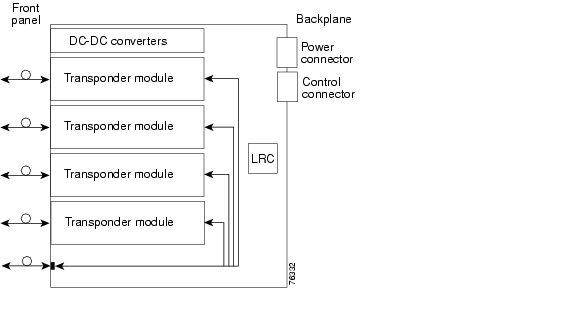
The nonsplitter 2.5-Gbps line card motherboard delivers the ITU wavelengths from the associated transponder modules to one optical connector on the front panel (see Figure 1-4). Use this optical connector to connect the line card motherboard to one mux/demux module, either directly or using the cross connect drawer.
Figure 1-4 Cisco ONS 15540 ESPx Nonsplitter Line Card Motherboard
10-Gbps Line Card Motherboards
A single system can hold up to eight dual-subslot 10-Gbps line card motherboards. There are two 10-Gbps line card motherboards available, splitter and nonsplitter.
The splitter protected motherboard provides trunk side protection. The motherboard has two external optical connectors at the bottom of the board, one for the east direction and one for the west direction. Both optical connectors carry the optical signal from a 10-GE transponder to the respective mux/demux motherboard. The two optical connectors are not selectable.
The nonsplitter motherboard is used in configurations where trunk side protection is not required. The motherboard has one external optical connector at the bottom of the board. The optical connector carries a band of wavepatch interfaces and the optical signal from the 10-GE transponder to the respective mux/demux motherboard.
Mux/Demux Motherboards
The mux/demux motherboards hold the optical mux/demux modules. Either slot 0 or slot 1 can be populated with a single mux/demux motherboard for unprotected operation, or both slots can be populated for protected operation.
The Cisco ONS 15540 ESPx chassis supports two types of mux/demux motherboards, with and without OSC support.
The mux/demux motherboards can accept up to four mux/demux modules:
•
•
•
The mux/demux motherboard can also accept a PSM for trunk fiber based protection along with the mux/demux modules.
OSC Support
The OSC is implemented with a dedicated laser and receiver for a 33rd wavelength (channel 0) on the mux/demux motherboard. The OSC is a per-fiber duplex management channel for communicating between Cisco ONS 15540 ESPx systems. It allows control and management traffic to be carried without the necessity of a separate Ethernet connection to each Cisco ONS 15540 ESPx, Cisco ONS 15540 ESP, and Cisco ONS 15530 in the network.
The OSC is established over a point-to-point connection and is always terminated on a neighboring node. By contrast, data channels may or may not be terminated on a given node, depending on whether the channels are express (pass-through) or add/drop.
The OSC carries the following types of information:
•
•
•
•
Note
Optical Mux/Demux Modules
The optical mux/demux modules are passive devices that optically multiplex and demultiplex a specific band of ITU wavelengths. In the transmit direction, the optical mux/demux modules multiplex signals transmitted by the transponder modules over optical cross connections and provide the interfaces to connect the multiplexed signal to the DWDM trunk side. In the receive direction, the optical mux/demux modules demultiplex the signals from the trunk side before passing them over optical cross connections to the transponder modules.
Optical Mux/Demux Modules and Channel Bands
There are two types of optical mux/demux modules—OADM (optical add/drop multiplexing) and terminal. Each module supports one or more 4-channel bands. The OADM modules support one or two bands (four channels or eight channels); the terminal mux/demux modules support eight bands (32 channels).
Table 1-6 lists the optical mux/demux modules that support each channel band. All modules are available with or without OSC support. For correspondence between channel numbers and wavelengths on the ITU grid, refer to the Cisco ONS 15540 ESPx Hardware Installation Guide.
Table 1-6 Optical Mux/Demux Modules and Supported Channel Bands
1-4
Band A
Band AB
Band AH
5-8
Band B
9-12
Band C
Band CD
13-16
Band D
17-20
Band E
Band EF
21-24
Band F
25-28
Band G
Band GH
29-32
Band H
1 A 32-channel terminal mux/demux module occupies all four subslots in a mux/demux motherboard.
OADM Modules
An OADM module adds a specified band of channels at a node and passes the other bands through. To support the 32-channel spectrum, there are eight different 4-channel modules and four different 8-channel modules.
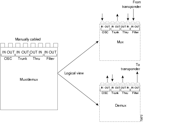
Figure 1-5 shows the physical layout of the Cisco ONS 15540 ESPx OADM module with front panel optical connectors along with a logical view of its multiplexing and demultiplexing functions. Optical signals received from the transponder, the Thru IN connector, and the OSC IN connector are multiplexed and sent through the Trunk OUT connector. The optical signal received from the Trunk IN connector is demultiplexed and the OSC signal is sent to the OSC OUT connector; the dropped channels are sent to the transponder; and the passed channels are sent to the Thru OUT connector.
Figure 1-5 Cisco ONS 15540 ESPx Optical Add/Drop Mux/Demux Module
32-Channel Terminal Mux/Demux Modules
The 32-channel terminal mux/demux module is based on AWG (arrayed waveguide grating) technology and supports the ITU wavelengths within the AH band (channels 1-32) and optionally the OSC. The 32-channel module installs in either slot 0 or slot 1 and supports front panel optical filter connectors, and it occupies all four subslots.
Because of their more favorable optical power loss characteristics, terminal mux/demux modules may be preferred at nodes where selective add/drop is not required, such as in a point-to-point topology or at the hub node in a hubbed ring topology.
Optical Mux/Demux Module Configurations and Cabling
The modular nature of the mux/demux motherboard allows optical mux/demux modules to be added as needed to support the desired number of client signals. In the case of add/drop mux/demux modules, the capacity can be increased with the addition of 4- or 8-channel modules to support increased channel demand or the requirements of a meshed ring topology.
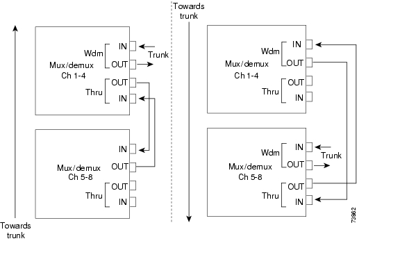
The 4- or 8-channel add/drop modules can be combined in a cascading fashion using optical fiber cables with MU connectors. Figure 1-6, for example, shows how two 4-channel modules are cabled together to upgrade a point-to-point configuration from 4 channels to 8 channels.
Figure 1-6 Cascaded 4-Channel Mux/Demux Modules
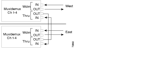
In ring configurations, channels that are not destined for a particular node are passed through that node and sent back on the ring. Figure 1-7 shows an example of how two 4-channel mux/demux modules might be cabled in a protected ring configuration.
Figure 1-7 4-Channel Mux/Demux Modules in a Protected Ring Configuration
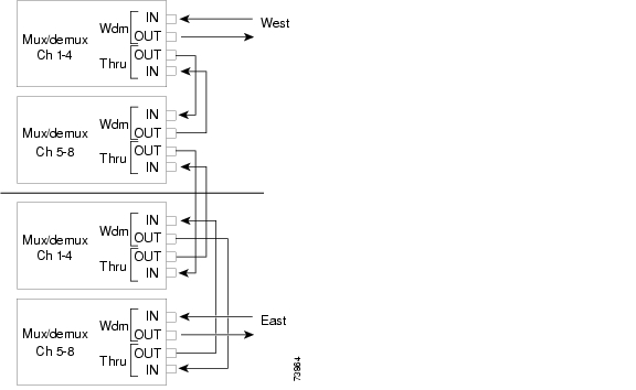
In some ring topologies, cascading add/drop mux/demux modules may be required to support the add/drop requirements of the configuration. Figure 1-8 shows one example.
Figure 1-8 Cascaded Add/Drop Mux/Demux Modules in a Protected Ring Configuration
PSMs
The PSM (protection switch module) provides trunk fiber protection for Cisco ONS 15540 ESPx systems configured in point-to-point topologies. The PSM sends the signal from a mux/demux module or a transponder module in both the west and east directions. It receives both the west and east signals and selects one to send to the mux/demux module or the transponder module. Both nodes in the network topology must have the same shelf configuration. When a trunk fiber cut occurs on the active path, the PSM switches the received signal to the standby path. The PSM can protect up to 32 data channels and the OSC (see Figure 1-9).
The PSM also has an optical monitor port for testing the west and east receive signals. This port samples one percent of the receive signal, which can be monitored with an optical power meter.
Figure 1-9 PSM Architecture
Cross Connect Drawer
The Cisco ONS 15540 ESPx design allows access to all optical connectors from the front of the shelf. For futher cabling flexibility, you can also use a cross connect drawer. This is particularly useful for adding and dropping fewer than four channels on a node that contains 4-channel, 8-channel, or 32-channel mux/demux modules. For example, you can cross connect channels 1 and 2 in band A from the west mux/demux module to a transponder module to add and drop at the node and cross connect channels 3 and 4 to pass through to the east mux/demux module unchanged. Each cross connect drawer supports a maximum of 8 protected channels. Protecting more than 8 channels requires additional cross connect drawers.
You can also use the cross connect drawer to receive ITU signals from other DWDM shelves, such as the Cisco ONS 15530, to multiplex and demultiplex the same as signals generated on the Cisco ONS 15540 ESPx shelf.
Processors Cards
The Cisco ONS 15540 ESPx includes two processor cards for redundancy. Each processor consists of a number of subsystems, including a CPU, a system clock, Ethernet switch for communicating between processors and with the LRC (line card redundancy controller) on the mux/demux motherboards and line card motherboards, and a processor redundancy controller. The active processor controls the node, and all cards in the system make use of the system clock and synchronization signals from the active processor.
The processor card is equipped with a console port, a Fast Ethernet interface for Telnet access and network management, and an auxiliary port. There are two slots for Flash PC Cards or Flash disks.
On the processor card front panel are LEDs that display the status of critical, major, and minor signals, as well as the status of alarm cutoff and history conditions. The alarm signals from the processor go to an alarm daughterboard on the backplane, which has a connector for central office alarm facilities.
The processor cards run Cisco IOS software and support the following features:
•
•
•
•
•
•
•
•
•
•
•
•
•
Processor Redundancy and Online Insertion and Removal
When the Cisco ONS 15540 ESPx is powered up, the two processors engage in an arbitration process to determine which will be the active and which will be the standby. Previous power state information is stored in the processor non-volatile random access memory (NVRAM). The processor that was previously active reassumes the active role. During operation, the two processors remain synchronized (application states, running and startup configurations, system images), and the two clocks are maintained in phase alignment. The operational status of each processor is monitored by the processor redundancy controller of the other processor through the backplane Ethernet. In the event of a failure or removal of an active processor, the standby processor immediately takes over and assumes the active role. Once the problem on the faulty card has been resolved, it can be manually restored to the active function.
In addition to providing protection against hardware or software failure, the redundant processor arrangement also permits installing a new Cisco IOS system image without system downtime. For more information about processor redundancy operation, as well as other software features, refer to the
Cisco ONS 15540 ESPx Configuration Guide.System and Network Management
The Cisco ONS 15540 ESPx is fully manageable through the following three mechanisms: the in-band message channel, the OSC, and a direct Ethernet connection to the NME (network management Ethernet) on the processor card. While all shelves will be equipped with at least one processor card, provisioning the OSC is optional, and the in-band message channel is only available on the 10-GE transponder modules.
All three mechanisms can be deployed within a single network. Each mechanism is associated with an interface that can be assigned an IP address. Management information will be routed between these interfaces.
Different levels of availability exist for each of these management mechanisms. High availability for the direct NME connection can be achieved with redundant processor cards. The OSC becomes highly available when it is provisioned on both the working and protection trunk fibers. The availability of a particular in-band message channel will mirror the availability of the ITU wavelength with which it is associated.
In-Band Message Channel
The in-band message channel establishes a method for providing in-band, per-wavelength OAM&P (operations, administration, management, and provisioning) functions.
The in-band OAM&P messages carry the following types of information:
•
•
•
•
–
–
–
–
•
In-Band Message Channel Consideration
The following considerations apply for the in-band message channel:
•
•
•
OSC
The OSC is an out-of-band method for providing OAM&P functions on a 33rd wavelength. The OSC supports a message channel that functions like the SONET DCC for management and provisioning. Messages transit the network hop-by-hop, and can be forwarded or routed according to established routing protocols. The OSC can be used to carry traffic to a network management system, or to carry other internodal management traffic such as link management, fiber failure isolation, performance monitoring, alarms, and APS protocol messages.
OSC Considerations
The following considerations apply for the OSC:
•
•
•
NME
The NME is a 10/100 Ethernet port on the processor card. You can connect this port to a router and configure the interface to route messages using established routing protocols. The NME can be used to carry traffic to a network management system.
Note
NME Considerations
The following considerations apply to the NME:
•
•
Comparison of In-Band Message Channel, SONET, and OSC
Table 1-7 compares the features provided by the in-band message channel, SONET, and OSC.
Table 1-7 Comparison of the In-Band Message Channel, SONET, and OSC
Management reach
Per fiber section
Per wavelength
Per wavelength
Fault isolation and topology discovery
Hop-by-hop fiber (physical topology)
End-to-end wavelength (logical topology)
End-to-end wavelength (logical topology)
Payload
Separate out-of-band channel
10-GE, GE, ESCON, Fibre Channel, FICON2
SONET (OC-n)
Management channel
Per fibre via a 33rd wavelength (channel 0)
Per wavelength via a message byte
Per wavelength via section DCC
Performance monitoring
OSC protocol
8B/10B(GE), 64/66B (10-GE), HEC3 , frame FCS
Section BIP4
1 SONET based management is not supported on the Cisco ONS 15540 ESPx and is included for comparison with the in-band message channel only.
2 ESCON, Fibre Channel, and FICON traffic carrying in-band message channel messages originate in a Cisco ONS 15530 system connected to the Cisco ONS 15540 ESPx by way of a 10-Gbps uplink card to the 10-GE transponder module.
3 HEC = Header Error Control
4 BIP = bit interleaved parity
For the most comprehensive set of monitoring and management capabilities, use both the in-band message channel and OSC on your network. The in-band message channel provides fault isolation and monitoring at the wavelength level, and OSC provides that functionality for the fiber.
![]()
![]()
![]()
![]()
![]()
![]()
![]()
![]()
Posted: Fri Feb 25 16:24:03 PST 2005
All contents are Copyright © 1992--2005 Cisco Systems, Inc. All rights reserved.
Important Notices and Privacy Statement.