|
|

Table Of Contents
Displaying Wdmsplit Interface Information
Configuring Trunk Fiber Based Protection
Displaying Trunk Fiber Protection Configuration
About Switchovers and Optical Power Thresholds
Post-Amplified and Preamplified Topologies
Configuring Optical Power Thresholds
Displaying Optical Power Threshold Configuration
Configuring Wdmsplit Interfaces in the Network Topology
Displaying Topology Information for Wdmsplit Interfaces
Configuring PSM Interfaces
This chapter describes how to configure PSM (protection switch module) interfaces and patch connections on the Cisco ONS 15540 ESPx. This chapter includes the following sections:
•
Enabling Wdmsplit Interfaces
•
•
•
•
•
Note
About the PSM
The PSM (protection switch module) provides trunk fiber protection for Cisco ONS 15540 ESPx systems configured in point-to-point topologies. The PSM sends the signal from a mux/demux module or a transponder module to both the west and east directions.
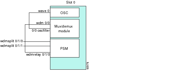
Figure 6-1 shows an example of PSM interfaces and their optical patch connections to a mux/demux module.
Figure 6-1 Optical Patch Connection Example Between a PSM and a Mux/Demux Module
Enabling Wdmsplit Interfaces
To enable the PSM wdmsplit interfaces, perform the following tasks, starting in global configuration mode:
Example
The following example shows how to enable wdmsplit interfaces:
Switch(config)# interface wdmsplit 0/0/0Switch(config-if)# no shutdownSwitch(config-if)# exitSwitch(config)# interface wdmsplit 0/0/1Switch(config-if)# no shutdownDisplaying Wdmsplit Interface Information
The following example shows how to display wdmsplit interface information.
Switch# show interface wdmsplit 0/1/0WdmSplit0/1/0 is administratively down, line protocol is downStatus :ActiveReceived power :0.00 dBm (EF9)Threshold Value :-22.00 dBm (8CE)Optical threshold monitored for :Receive Power (in dBm)Low alarm value = -22.0 dBm (default)Low Alarm Severity = majorLow warning value = -20.0 dBm (default)Low Warning Severity = not alarmedHigh alarm value = -2.0 dBm (default)High Alarm Severity = majorHigh warning value = -4.0 dBm (default)High Warning Severity = not alarmedHardware is split wavelength_add_dropConfiguring Trunk Fiber Based Protection
To configure trunk fiber protection on the wdmsplit interfaces, perform the following steps, beginning in global configuration mode:
For more information on configuring APS and trunk fiber based protection, refer to Chapter 7, "Configuring APS."
Examples
The following example shows how to configure trunk fiber protection:
Switch(config)# redundancySwitch(config-red)# associate group psm-groupSwitch(config-red-aps)# aps working wdmsplit 0/1/0Switch(config-red-aps)# aps protection wdmsplit 0/1/1Switch(config-red-aps)# aps message-channel ip far-end group-name psm-group ip-address 172.18.44.93Switch(config-red-aps)# aps enableDisplaying Trunk Fiber Protection Configuration
To display the trunk fiber configuration, use the following EXEC command:
show aps {detail | group name | interface wavepatch slot/subcard/port}
Displays detailed APS configuration information for groups and interfaces.
Note
Examples
The following example shows how to display the protocol encapsulation configuration of a wdmsplit interface:
Switch# show aps group psm-groupAPS Group psm-group :architecture.: 1+1, remote prov: 1+1span.........: end-to-endprot. mode...: network side wdm splitterdirection....: prov: bi, current: bi, remote prov: birevertive....: noaps state....: enabled (associated)request timer: holddown: 5000 ms, max: 15000 ms, count 2msg-channel..: ip (up), psm-group, 172.18.44.93created......: 22 hours, 11 minutesauto-failover: disabledtransmit k1k2: sf-lp, 0, 0, 1+1, bireceive k1k2: reverse-request, 0, 0, 1+1, biswitched chan: 0protection(0): WdmSplit0/0/1 (STANDBY - DOWN): channel request: sf-lp: switchover count: 7: last switchover: 18 minutesworking...(1): WdmSplit0/0/0 (ACTIVE - UP): channel request: no-request: switchover count: 7: last switchover: 18 minutesAbout Switchovers and Optical Power Thresholds
The switchovers for trunk fiber protection on the PSM are controlled by an optical power threshold value set in the CLI. The value to set is determined by the characteristics of the point-to-point topology. The PSM supports the following types of point-to-point topologies:
•
•
•
Note
Unamplified Topologies
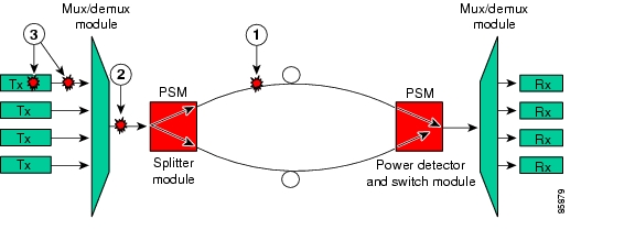
A topology without amplification is the simplest case. Figure 6-2 shows an unamplified topology and the locations where failures can occur.
Figure 6-2 Point-to-Point Topology Without Amplification
Note
The switching behavior for the failures is as follows:
•
The receive power on the active path drops below the minimum detectable level (-31 dBm) and the PSM switches over to the standby path.
•
In this case, the receive power on both the active and standby paths drops below the minimum detectable level. However, a switchover will occur if the auto-failover is enabled in the hardware. Since the system monitors the standby signal at 1 second intervals, the system might not detect the standby signal failure before the switchover occurs. After this switchover, no further switchovers occur.
•
No switchover occurs because the change in the channel power is less than 15 dB.
The recommended low alarm threshold value for this topology is -28 dBm and the low warning threshold is at least -26 dBm.
Post-Amplified Topologies
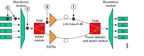
Figure 6-3 shows an example topology with post-amplification and the locations where failures can occur.
Figure 6-3 Point-to-Point Topology with Post-Amplification
Trunk fiber cut
Mux/demux module-to-PSM patch cable cut
PSM-to-EDFA patch cable cut
Individual channel failures
Note
The switching behavior for the failures is as follows:
•
The receive power on the active path drops below the minimum detectable level (-31 dBm) and the PSM switches over to the standby path.
•
The EDFA generates -9 dBm of noise on the active path so the PSM receives (-9 - D) dBm signal power where D is the link loss between the EDFA and the PSM receiver. If the low alarm optical threshold is set correctly, the PSM switches over to the standby path.
•
The EDFA generates -9 dBm of noise on both paths so the PSM receives (-9 - D) dBm signal power where D is the link loss between the EDFA and the PSM receiver. If auto-failover is enabled and the low alarm optical threshold is set correctly, the PSM switches to the standby path before it detects that the standby path has also failed. No further switchovers occur.
•
No switchover occurs because the change in the channel power is less than 15 dB.
The recommended value for the low alarm optical threshold is (-6 - D) dBm and the low warning threshold is at least 2 dB higher.
Post-Amplified and Preamplified Topologies
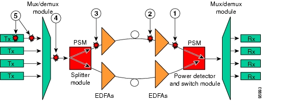
Figure 6-4 shows an topology with post-amplification and preamplification and the locations where failures can occur.
Figure 6-4 Point-to-point Topology with Post-Amplification and Pre-Amplification
EDFA-to-PSM patch cable cut
Mux/demux module-to-PSM patch cable cut
Trunk fiber cut
Individual channel failures
PSM-to-EDFA patch cable cut
Note
The switching behavior for the failures is as follows:
•
The receive power on the active path drops below the minimum detectable level (-31 dBm) and the PSM switches over to the standby path.
•
The EDFA generates -9 dBm of noise so the PSM receives (-9 - L) dBm signal power where L is the output attenuation from the EDFA. The PSM switches over to the standby path if the low alarm threshold is correctly configured.
•
The receive power drops, but not below the minimum detectable level because of the cumulative noise from the two EDFAs. The PSM switches over to the standby signal if the low alarm threshold is correctly configured.
•
The receive power drops but not below the minimum detectable level because of the cumulative noise from the two EDFAs. If auto-failover is enabled, the PSM switches to the standby path before it detects that the standby path has also failed. No further switchovers occur.
•
No switchover occurs because the change in the channel power is less than 15 dB.
Figure 6-5 shows an example topology and the locations where failures can occur.
Figure 6-5 Failure Scenario with Noise from Two EDFAs
You can calculate the noise using the following formula:
10 dB * log(10((-9)/10) + 10((-9-D+17)/10)) dB - L dB
where D is the link loss between the EDFAs and L is equal to 17 minus the configured gain on the EDFA closest to the PSM receiver.
The recommended value for the low alarm optical threshold is the calculated noise value plus 3 dBm.
Set the low warning threshold at least 2 dB higher.
Configuring Optical Power Thresholds
The optical power thresholds provide a means of monitoring the signal power received from the active trunk fiber path. Two types of thresholds are provided:
•
•
When the low alarm threshold is crossed on the active path, the PSM switches over to the standby path. When either of the thresholds are crossed, the system sends messages to the console and generates traps, if traps are enabled.
To configure optical power thresholds for wdmsplit interfaces on a PSM, perform the following steps, beginning in global configuration mode:
Examples
The following example shows how to configure optical power thresholds for wdmsplit interfaces on a PSM:
Switch(config)# interface wdmsplit 0/1/0Switch(config-if)# optical threshold power receive low alarm -27Switch(config-if)# optical threshold power receive low warning -25Switch(config-if)# exitSwitch(config)# interface wdmsplit 0/1/1Switch(config-if)# optical threshold power receive low alarm -26Switch(config-if)# optical threshold power receive low warning -24Displaying Optical Power Threshold Configuration
To display the optical power thresholds for a wdmsplit interface, use the following EXEC command:
Example
The following example shows how to display the optical threshold configuration for an interface:
Switch# show interfaces wdmsplit 0/1/0WdmSplit0/1/0 is administratively down, line protocol is downStatus :ActiveReceived power :0.00 dBm (EF9)Threshold Value :-22.00 dBm (8CE)Optical threshold monitored for :Receive Power (in dBm)Low alarm value = -22.0 dBm (default)Low Alarm Severity = majorLow warning value = -20.0 dBm (default)Low Warning Severity = not alarmedHardware is split wavelength_add_dropConfiguring Patch Connections
To configure patch connections between a PSM and a mux/demux module, use the following global configuration command:
Note
Example
The following example shows how to configure the patch connections between a PSM and a mux/demux module:
Switch#configure terminalSwitch(config)#patch wdm 0/0 wdmrelay 0/1/0Displaying Patch Connections
To display the patch connections, use the following privileged EXEC command:
show patch [detail]
Displays the patch connections.
show interfaces {wdm slot/subcard1 wdmrelay | slot/subcard2/port | wavepatch slot/subcard/port}
Displays the interface information.
Example
The following example shows the patch connections:
Switch# show patchPatch Interface Patch Interface Type Dir Error------------------ ------------------ --------- ---- ----------------Wdm0/0 WdmRelay0/1/0 USER BothSwitch# show interfaces wdm0/0Wdm0/0 is up, line protocol is upPatched Interface(s) :WdmRelay0/1/0Wdm Hw capability:N/ANum of Wavelengths Add/Dropped:5List of Wavelengths:0, 13, 14, 15, 16Hardware is wavelength_add_dropConfiguring Wdmsplit Interfaces in the Network Topology
The wdmsplit interfaces on a PSM do not support CDP and must be manually configured in the network topology.
Note
Note
To add wdmsplit interfaces to the network topology, perform the following steps on the wdmsplit interfaces on both the nodes in the point-to-point network topology, beginning in global configuration mode:
Example
The following example shows how to add wdmsplit interfaces to the network topology:
Switch(config)# interface wdmsplit 1/1/0Switch(config-if)# topology neighbor name NodeB port name wdmsplit1/1/0Switch(config-if)# topology neighbor agent ip-address 10.1.1.1Switch(config-if)# exitSwitch(config)# interface wdmsplit 1/1/1Switch(config-if)# topology neighbor name NodeB port name wdmsplit1/1/1Switch(config-if)# topology neighbor agent ip-address 10.1.1.1Displaying Topology Information for Wdmsplit Interfaces
To display the topology information for wdmsplit interfaces, use the following EXEC command:
Example
The following example shows how to display the topology information:
Switch# show topology neighborPhysical Topology:Local Port Neighbor Node Neighbor Port Link Dirn---------- ------------- ------------- ---------WdmSplit0/1/0 PSM-2 wdms0/1/0 BothWdmSplit0/1/1 PSM-2 wdms0/1/1 Both
![]()
![]()
![]()
![]()
![]()
![]()
![]()
![]()
Posted: Thu Feb 16 04:05:29 PST 2006
All contents are Copyright © 1992--2006 Cisco Systems, Inc. All rights reserved.
Important Notices and Privacy Statement.