|
|

Table Of Contents
Basic Network Verification Procedures
NTP-23 Verify the Optical Power Budget Between Nodes
NTP-24 Verify the Connectivity Between OSC Modules
NTP-25 Verify the Topology Neighbor Connectivity
NTP-26 Verify the Power Levels
NTP-27 Test the Optical Transmission Quality
NTP-28 Verify the Optical Protection Configuration
DLP-54 Verify the APS Configuration
DLP-55 Verify the Splitter Protection Operation
DLP-56 Verify the Y-Cable Protection Operation
Basic Network Verification Procedures
This chapter describes the procedures for basic network-level verification.
Note
Before performing the procedures in this chapter, the nodes must have been installed and configured. All cabling must be complete.
Note
Before You Begin
This section lists the chapter non-trouble procedures (NTPs). Turn to a procedure for applicable tasks or detailed level procedures (DLPs).
1.
2.
3.
4.
5.
6.
NTP-23 Verify the Optical Power Budget Between Nodes
Note
Note
Step 1
Step 2
Step 3
Step 4
Switch# configure terminalSwitch(config)# interface wavepatch 2/0/0Switch(config-if)# shutdownSwitch(config-if)# exitSwitch(config)# interface wavepatch 2/0/1Switch(config-if)# no shutdownRepeat Step 3.
Step 5
Step 6
If the results for a particular wavelength do not match, make sure the connectors are fully inserted and the transponder line cards are correctly installed. Clean the fibers and connectors, if necessary. Rerun the test.
If the results still do not match, there might be a hardware problem.
Step 7
NTP-24 Verify the Connectivity Between OSC Modules
Step 1
Switch# show oscp interface wave 2/0Codes: Bndl - bundling identifier, Pri - OSCP selection priorityOSCP - dedicated wavelength channel, CDL - in-band wavelength channelOSCP Interface(s)Local Port Port ID Type Status OSCP St Bndl Pri Rem Port ID Rem Node Id~~~~~~~~~~~~~ ~~~~~~~ ~~~~ ~~~~~~ ~~~~~~~ ~~~~ ~~~ ~~~~~~~~~~~ ~~~~~~~~~~~~~~Wave2/0 1000000 OSCP Active 2way 0 0 1000000 0000.1644.28fbStep 2
If the status is not active, the interface is not enabled. Perform a no shutdown command on the OSC wave interface.
Step 3
NTP-25 Verify the Topology Neighbor Connectivity
Step 1
Switch# show topology neighbor detailPhysical Topology:Local Port: Wdm0/0Neighbor Node : node3Neighbor Port : Wdm0/1Neighbor Agent Address: 172.20.50.21Neighbor Discovery : Via CDP (Proxy Port: Wave2/1)Link Direction : BothLocal Port: Wdm0/1Neighbor Node : node1Neighbor Port : Wdm0/0Neighbor Agent Address: 172.20.42.27Neighbor Discovery : Via CDP (Proxy Port: Wave2/0)Link Direction : BothStep 2
Step 3
NTP-26 Verify the Power Levels
Purpose
This procedure verifies the expected power levels provided by a network design.The measured power should be within an acceptable range from the expected power
Tools/Equipment
OSA (optical spectrum analyzer)
Prerequisite Procedures
NTP-14 Verify the System Configuration, page 3-43
Required/As Needed
Required
Onsite/Remote
Onsite
Security Level
Privileged
Step 1
Step 2
Step 3
Step 4
Step 5
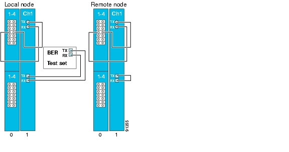
NTP-27 Test the Optical Transmission Quality
Purpose
This procedure tests optical transmission quality between the nodes that add and drop the same channel.
Tools/Equipment
BER test set
Prerequisite Procedures
NTP-14 Verify the System Configuration, page 3-43
Required/As Needed
Required
Onsite/Remote
Onsite
Security Level
Privileged
Step 1
Step 2
Note
Figure 5-1 Example Setup for Testing Bit Error Rate
Step 3
Step 4
Step 5
Step 6
a.
b.
c.
Step 7
Step 8
NTP-28 Verify the Optical Protection Configuration
Step 1
Step 2
Step 3
DLP-54 Verify the APS Configuration
Step 1
Switch# show aps group sonet-groupAPS Group sonet-group :architecture.: 1+1, remote prov: 1+1span.........: end-to-endprot. mode...: client side y-cabledirection....: prov: bi, current: bi, remote prov: birevertive....: noaps state....: enabled (associated)request timer: holddown: 5000 ms, max: 15000 ms, count 2msg-channel..: auto (up on osc)created......: 17 hours, 10 minutesauto-failover: enabledtransmit k1k2: reverse-request, 1, 1, 1+1, bireceive k1k2: forced-switch, 1, 1, 1+1, biswitched chan: 1protection(0): Transparent7/0/0 (ACTIVE - UP), Wave7/0 (UP): channel request: no-request: switchover count: 2: last switchover: 15 hours, 14 minutesworking...(1): Transparent4/0/0 (STANDBY - UP), Wave4/0 (UP): channel request: no-request: switchover count: 3: last switchover: 14 hours, 41 minutesStep 2
Step 3
Step 4
Step 5
DLP-55 Verify the Splitter Protection Operation
Purpose
This task verifies the operation of the splitter protection configuration on your network.
Tools/Equipment
SONET analyzer or Ethernet analyzer
Prerequisite Procedures
NTP-14 Verify the System Configuration, page 3-43
Required/As Needed
As needed
Onsite/Remote
Onsite or remote
Security Level
Privileged
Note
Step 1
a.
b.
c.
Step 2
a.
b.
c.
Step 3
a.
b.
aps switch group-name manual working-to-protection
c.
Step 4
a.
b.
aps switch group-name manual protection-to-working
c.
Step 5
DLP-56 Verify the Y-Cable Protection Operation
Purpose
This task verifies the operation of the y-cable protection configuration on your network.
Tools/Equipment
SONET analyzer or Ethernet analyzer
Prerequisite Procedures
NTP-14 Verify the System Configuration, page 3-43
Required/As Needed
As needed
Onsite/Remote
Onsite or remote
Security Level
Privileged
Note
Step 1
a.
b.
c.
Step 2
a.
b.
c.
Step 3
a.
b.
aps switch group-name manual working-to-protection
c.
Step 4
a.
b.
aps switch group-name manual protection-to-working
c.
Step 5
![]()
![]()
![]()
![]()
![]()
![]()
![]()
![]()
Posted: Tue May 17 00:32:21 PDT 2005
All contents are Copyright © 1992--2005 Cisco Systems, Inc. All rights reserved.
Important Notices and Privacy Statement.