cc/td/doc/product/mels/15530
hometocprevnextglossaryfeedbacksearchhelp
PDF

Table Of Contents

Network Turn Up of Amplified Ring Topologies with Per-Channel Equalization

Before You Begin

NTP-29 Initial Deployment

Prerequisites

Overview

DLP-57 Equalize the Optical Power at the Site

DLP-58 Equalize the Optical Power in the Network

NTP-30 Add or Remove Data Channels

Prerequisites

DLP-59 Add a Data Channel

DLP-60 Remove a Data Channel

NTP-31 Add or Remove the OSC

DLP-61 Add the OSC

DLP-62 Remove the OSC

NTP-32 Remove and Reinsert a Transponder Line Card or OSC Module Online


Network Turn Up of Amplified Ring Topologies with Per-Channel Equalization


This chapter describes how to deploy amplified meshed ring and hubbed ring topologies with per-channel equalization.

Before You Begin

This section lists the chapter non-trouble procedures (NTPs). Turn to a procedure for applicable tasks or detailed level procedures (DLPs).

1. 29 Initial Deployment

2. 30 Add or Remove Data Channels

3. 31 Add or Remove the OSC

4. 32 Remove and Reinsert a Transponder Line Card or OSC Module Online

NTP-29 Initial Deployment

Purpose

This procedure describes how to initially turn up a Cisco ONS 15530 amplified ring network with per-channel equalization.

Tools/Equipment

Optical TAPs installed on the trunk output of every site

OPM (optical power meter)

OSA (optical spectrum analyzer)

Prerequisite Procedures

NTP-14 Verify the System Configuration, page 3-43 for every node in the network

Required/As Needed

As needed

Onsite/Remote

Onsite

Security Level

None


Step 1 Complete the "DLP-57 Equalize the Optical Power at the Site" task.

Step 2 Complete the "DLP-58 Equalize the Optical Power in the Network" task.


Prerequisites

This procedure requires the following:

You are familiar with the Cisco ONS 15530, its components, and the Cisco IOS CLI (command-line interface).

Cisco ONS 15530 technical documentation is available and consulted during installation, configuration, and testing. You can find the documentation at this URL:

http://www.cisco.com/univercd/cc/td/doc/product/mels/15530/index.htm

You have used design analysis or a design tool for the network to determine the target power for channel power equalization (Ptarget) at each site, plus EDFA gains (Gain). There may be exceptions in the design analysis where the full equalization is not applied to a particular span. In those cases, the design analysis provides a minimum value to use as the local target power.


Note The acceptable tolerance that is provided in the procedure for equalizing to the proper Ptarget values should already be accounted for in the design analysis phase.


Certain designs that are optimized and do not follow the strict per-channel equalization rules. The per-channel equalization rule for equalizing added channels to pass through channels are relaxed in nonamplified spans. During initial deployment, you can equalize the added channels d to a minimum power derived from the downstream Ptarget value. The Gain for amplifiers is usually set to a mid-range value and then adjusted during the final network equalization.

The complete site cabling diagram is available from the design analysis or the design tool. This diagram provides DWDM cabling detail for interchassis and intrachassis connections.

All Cisco ONS 15530 components are installed and optically characterized as described in Chapter 2, "Basic Hardware Installation Procedures," Chapter 3, "Software Setup Procedures," the Cisco ONS 15530 Hardware Installation Guide, and the Cisco ONS 15530 Configuration Guide and Command Reference. This includes the OSC modules, transponder line cards, WB-VOA modules, PB-OE modules, and OADM modules needed in the design. All trunk connections have a TAP.


Note The final OADM modules for the design should be installed at initial deployment to allow for future uninterrupted upgrades.


You have selected and recorded the Reference Node. For hubbed ring topologies, use the hub node as the Reference Node. For meshed ring topologies, use the node with the optical seam.

You have selected and recorded the Reference Channel on each node. Select an added data channel that is readily available in the initial stage as the Reference Channel. The Reference Channel is initially used to achieve the desired Ptarget with high degree of accuracy. We recommend that you select a data channel because not all deployments require the OSC (Optical Supervisory Channel).


Note In the first phase of the deployment (Site Equalization) for meshed rings, you might not start from the Reference Node because the network sites are not connected at that point. During the last phase (Network Equalization), we recommend starting from Reference Node so you can make the initial adjustments to the PB-OE modules in the optical seam.


If there are EDFAs in the optical path, their input ports are disconnected.

Perform a procedure first in one direction (for example, clockwise). After completing the first pass, perform the same procedure for the other direction (counter-clockwise).


Note These turn-up procedures require multiple passes through the network.


Overview

There are two main steps for per-channel equalization in the initial deployment of the amplified ring:


Step 1 Site power equalization.

At this point the site trunks are not connected to an EDFA or to another site. The objective is to equalize the added channels to Ptarget. The procedure starts with equalizing the Reference Channel to Ptarget using an OPM (optical power meter). Then the procedure equalizes the rest of the added channels to the Reference Channel using an OSA (optical spectrum analyzer).

Step 2 Network power equalization.

At the end of the site power equalization procedure the site trunks are connected to an EDFA or to another site. The network power equalization procedure consists of starting from a Reference Node and adjusting amplifier gain to equalize the express channels to the Reference Channel.


DLP-57 Equalize the Optical Power at the Site

Purpose

This task equalizes the optical power of the added channels to the selected Reference Channel at the node site.

Tools/Equipment

OPM (optical power meter)

OSA (optical spectrum analyzer)

Prerequisite Procedures

DLP-23 Connect OADM Modules, WB-VOA Modules, and Transponder Line Cards for Per-Channel Equalization, page 2-52

NTP-14 Verify the System Configuration, page 3-43

Prerequisites

Required/As Needed

Required

Onsite/Remote

Onsite or remote

Security Level

Privileged


Assumptions

All conditions described in the "Prerequisites" section are met or considered.

The following states apply to the corresponding components following the initial installation.

ITU lasers on all transponder line cards are turned off using the shutdown command on the wave interfaces.

WB-VOA module attenuations are set to the minimum values using the optical attenuation manual command on the voain interfaces.

PB-OE module attenuations are set to the minimum using the optical attenuation manual command on the voafilterin subinterfaces.

EDFA gain values are set to the minimum.

Trunk or EDFA connections are not in place.


Step 1 Start with the Reference Node.

Step 2 Select the Reference Channel as described in the "Prerequisites" section.

Step 3 Make sure that the client services are connected to the transponder line card and that the transparent interface is modulated with the correct protocol encapsulation or clock rate to provide more accurate power readings.

Step 4 Turn on the transponder line card ITU laser for the Reference Channel using the no shutdown command on the wave interface.


Note At this point the Reference Channel should be the only active signal on the node output trunk. Make sure that the MID_IN and MID_OUT ports on the OADM modules are not cabled yet. This prevents pass through channels from interfering with the added channel equalization procedure.


Step 5 Connect the OPM to the TRUNK_OUT port on the OADM module to monitor the Reference Channel power.


Note Use the TAP trunk output and not the TAP monitoring port to provide a higher degree of accuracy for the Reference Channel that is used for equalizing the other channels.


Step 6 Adjust the attenuation of the WB-VOA module using the optical attenuation manual command on the voain interface to bring the Reference Channel power within ±0.1 dB of Ptarget.

Step 7 Issue a show interfaces voain command on the WB-VOA module and record the power reading from the command output for future reference.

Step 8 Disconnect the OPM from the TRUNK_OUT port on the OADM module and connect an OSA.

Step 9 Perform the following steps for each of the other transponder line cards installed at this site:

a. Make sure that the client services are connect to the transponder line card and that the transparent interface is modulated with the correct protocol encapsulation or clock rate to provide more accurate power readings.

b. Turn the ITU laser on using the no shutdown command on the wave interface.

c. Monitor the added channel using the OSA connected to the TRUNK_OUT port on the OADM module.

d. While monitoring the newly added channel, adjust the WB-VOA module output using the optical attenuation manual command on the voain interface to equalized this channel to the Reference Channel.


Note The acceptable tolerance while setting attenuation and equalizing the new channel is within ±0.5 dB with respect to the Reference Channel.


e. Use the show interface voain command on the WB-VOA module to obtain the power reading and record it for future reference.

Step 10 Equalize the OSC (if present) as described in Step 9 for added data channels, except for modulating the client interface.


Note In some designs, the OSC is not completely equalized due to its hop-by-hop nature and the receiver sensitivity range of the OSC module. Depending on the desired degree of equalization, set the appropriate attenuation for the OSC.


Step 11 Record the optical power of the data channels measured by the OSA at the TAP trunk output when the added channel equalization is completed,.

Step 12 Disconnect the OSA from the trunk and connect the trunk to the TRUNK_OUT port on the OADM in the desired direction.

Step 13 Switch the WB-VOA modules from manual attenuation to automatic control with the optical attenuation automatic command on the voain interfaces using the power readings of the WB-VOA modules recorded in Step 9 and Step 10.

Step 14 Make sure that the connections for the pass through (express) channels are completed by connecting the MID_IN and MID_OUT ports on the OADM modules as described in the "DLP-27 Connect the OADM Modules for Splitter or Line Card Protection" task on page 2-64.

Step 15 If a post amplifier is present, perform the following steps:

a. Connect the OADM module TRUNK_OUT port in the desired direction to the trunk input port on the post amplifier.

b. Use the setgainmean command to adjust the gain value on the EDFA as indicated in the design analysis.

c. Connect the OSA to the trunk output port of the post amplifier and read the power of all added channels. Record all power readings.

d. Using the OSA, verify that the actual gain values and gain tilt values agree with the design analysis. The gain tilt value is the difference between the highest and lowest gain values for all the added channels.

e. Disconnect the OSA and reconnect the trunk to the trunk output port on the post amplifier.

Step 16 Connect the incoming trunk (or preamplifier, if present) to the OADM module TRUNK_IN port in the desired direction.

Step 17 Move to the next downstream node.

Step 18 Connect to the OSA to the trunk, before the preamplifier (if present), and record all power readings.

Step 19 If a preamplifier is present, perform the following steps:

a. Connect the trunk to the trunk input port of the preamplifier.

b. Connect the OSA to the trunk output port of the preamplifier.

c. Use the setgainmean command to set the gain on the preamplifier as defined in the design analysis and record all power readings.

d. Using the OSA, verify that the actual gain values and gain tilt values agree with the design analysis. The gain tilt value is the difference between the highest and lowest gain values for all the added channels.

e. Disconnect the OSA and connect the trunk between the node and the preamplifier to the trunk input port on the preamplifier.

Step 20 Repeat Step 2 through Step 19 for the remaining nodes in the current direction.

Step 21 You have now equalized the added channels on all of the nodes in one direction. Repeat Step 1 through Step 20 for the other direction.


Note The added channels at every site are equalized to their appropriate Ptarget value or the power value designated by the design analysis but the pass through channels have not been considered yet.


Considerations

If you replace the Reference Channel transponder line card with a new transponder line card during the life of the network, you can use the remaining equalized channels can to adjust the replacement. Adjust and equalize the newly replaced Reference Channel to the average peak of the existing channels.

If you remove the Reference Channel and do not replace it with another transponder line card, the remaining equalized channels are left intact. If you add a new channel, you can equalize it to the average peak of the existing channels.

There are many ways to address the number of people and equipment needed (for example, the OSAs and OPMs). To minimize movements and coordination difficulties during troubleshooting, ideally you can have an individual with an OSA and OPM at every site with conference bridges available. However, this might not always be possible. You can use the following steps to efficiently address this issue:

1. Start with the Reference Node as the first site. Have individuals with OSAs and OPMs at three consecutive sites moving in one direction around the ring topology.

2. Complete the procedure in this section, including the specified monitoring and trunk connections, at the first and the second sites.

3. Then complete the procedure at the second and the third sites, while the individual who was at the first site goes to the fourth site in the ring topology, if one exists.

4. Complete this procedure on the next two nodes and continue around the ring until you reach the Reference Node.

Example

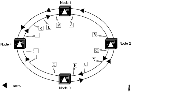
Figure 6-1 shows an example of a protected ring topology. Table 6-1 lists the detailed steps for the site equalization process.


Note Only the clockwise direction is considered. A similar process must performed for the counter-clockwise direction.


Figure 6-1 Example of a Protected Ring Network Topology

Table 6-1 Site Power Equalization Process Example 

Site
Steps
Test Location
Actions

Node 1

1 to  8

Point A

Start with Node 1 (the Reference Node), select a Reference Channel, and set and record the power for the Reference Channel based on the network design.

9 to  13

Point A

Equalize all other added channels on Node 1 relative to the Reference Channel and record the power values.

14

Node 1

Connect the pass through channels between the two OADM modules.

15


Not applicable. In the example, this span has no post amplifier after Node 1 in the clockwise direction.

16

Node 1

Connect the input trunk to the OADM module.

17

Node 2

Continue to Node 2.

18

Point B

Record power values at the end of the span between Node 1 and Node 2.

19


Not applicable. In the example, this span has no preamplifier before Node 2 in the clockwise direction.

Node 2

2 to  8

Point C

Select a Reference Channel and set the power for the Reference Channel based on the network design

9 to  13

Point C

Equalize all other added channels on Node 2 relative to the Reference Channel and record the power values.

14

Node 2

Connect the pass through channels between the two OADM modules.

15

Point D

Measure the power from the trunk output on the post amplifier and set the gain as defined in the design analysis.

16

Node 2

Connect the input trunk to the OADM module.

17

Node 3

Move to Node 2.

18

Point E

Record power values at the end of the span between Node 2 and Node 3.

19

Point F

Measure the power from the trunk output on the preamplifier and set the gain as defined in the design analysis.

Node 3

2 to  8

Node 3

Select a Reference Channel and set the power for the Reference Channel based on the network design

9 to  13

Point G

Equalize all other added channels on Node 3 relative to the Reference Channel and record the power values.

14

Node 3

Connect the pass through channels between the two OADM modules.

15


Not applicable. In the example, this span has no post amplifier after Node 3 in the clockwise direction.

16

Node 3

Connect the input trunk to the OADM module.

17

Node 4

Continue to Node 4.

18

Point H

Record power values at the end of the span between Node 3 and Node 4.

19

Point I

Measure the power from the trunk output on the preamplifier and set the gain as defined in the design analysis.

Node 4

2 to  8

Node 4

Select a Reference Channel and set the power for the Reference Channel based on the network design

9 to  13

Point J

Equalize all other added channels on Node 4 relative to the Reference Channel and record the power values.

14

Node 4

Connect the pass through channels between the two OADM modules.

15

Point J

Measure the power from the trunk output on the post amplifier and set the gain as defined in the design analysis.

16

Node 4

Connect the input trunk to the OADM module.

17

Node 1

Continue to Node 1.

18

Point K

Record power values at the end of the span between Node 4 and Node 1.

19

Point L

Measure the power from the trunk output on the preamplifier and set the gain as defined in the design analysis.


DLP-58 Equalize the Optical Power in the Network

Purpose

This task equalizes the optical power of the pass through channels to the added channels on the entire network.

Tools/Equipment

OSA (optical spectrum analyzer)

Prerequisite Procedures

57 Equalize the Optical Power at the Site

Prerequisites

Required/As Needed

Required

Onsite/Remote

Onsite or remote

Security Level

Privileged


Note The network power equalization phase might require a different approach at each site, such as the following:

No action indicated by the network design.

Equalize the express channels by adjusting attenuation settings on the seam or adjusting prior EDFA gain.

Make adjustments to the attenuation of the WB-VOA module for the remote upstream site based on the actual readings (since the analysis may consider the worst statistical values) to bring the local express channel powers inline with respect to the Reference Channel.


Assumptions

All added channels on all of the nodes have been equalized properly or all factors have been considered as outlined in the "DLP-57 Equalize the Optical Power at the Site" task.

Al the trunk connections are completed.


Step 1 Start at the Reference Node.

Step 2 Connect the OSA to the TAP trunk output.

Step 3 Monitor all channels using the OSA.

Step 4 Equalize the express channels to the added channels, as needed, by changing the attenuation setting of the optical seam PB-OE modules using the optical attenuation manual command on the voafilterin interfaces or by changing the attenuation setting of the WB-VOA modules at the remote upstream site.


Note For the hub node in hubbed ring topologies, all channels terminate on this node and no optical seam is required.


Step 5 Disconnect the OSA.

Step 6 Continue to the next downstream node and connect the OSA to the TAP trunk output.

Step 7 Equalize the express channels, as needed, by either adjusting the gain on the preamplifier using the setgainmean command or adjusting the attenuation setting on the WB-VOA module at the remote upstream site.

Step 8 Continue to the next node and repeat Step 2 through Step 7 on the remaining nodes in the network.


Considerations

While adjusting the express channels, the average peak can be used with respect to the Reference Channel if a single value is needed for all express channels.

We recommend having one individual with an OSA at each site for fully connecting the network and isolating problems during the network power equalization stage. However, it may not be practical to do so. Consider streamlining the number of staff and equipment needed as described in the "DLP-57 Equalize the Optical Power at the Site" task.

Example

Table 6-2 lists the detailed steps for the network power equalization process for the example network shown in Figure 6-1.


Note Only the clockwise direction is considered. A similar process must performed for the counter-clockwise direction.


Table 6-2 Network Power Equalization Process Example 

Site
Steps
Test Location
Actions

Node1

1 to  6

Point A

Start with the Reference Node. If this is a meshed ring topology, make any necessary adjustments to the PB-OE modules in the optical seam on this node.

Node 2

7 to  8

Point C

Make any necessary adjustments to the WB-VOA modules on Node 1 for the pass through channels.

Node 3

7 to  8

Point G

Make any necessary adjustments to the preamplifier gain setting.

Node 4

7 to  8

Point J

Make any necessary adjustments to the preamplifier gain setting.


NTP-30 Add or Remove Data Channels

Purpose

This procedure describes how to incrementally add a data channel to or remove it from an equalized network.

Tools/Equipment

Optical TAPs installed on the trunk output of every site

OPM (optical power meter)

OSA (optical spectrum analyzer)

Number 1 Phillips screwdriver

Prerequisite Procedures

29 Initial Deployment

Required/As Needed

As needed

Onsite/Remote

Onsite

Security Level

None


Step 1 As needed, complete the "DLP-59 Add a Data Channel" task to add a data channel to an existing equalized network.

Step 2 As needed, complete the "DLP-60 Remove a Data Channel" task to remove a data channel from an existing equalized network.


Prerequisites

The tasked outlined here rely on the following:

The final maximum OADM module configuration is in place.

The design analysis and values are available based on the final design.

DLP-59 Add a Data Channel

Purpose

This task adds a single data channel to an equalized network.

Tools/Equipment

Optical TAPs installed on the trunk output of every site

OPM (optical power meter)

OSA (optical spectrum analyzer)

Prerequisite Procedures

29 Initial Deployment

DLP-11 Install the WB-VOA Module, page 2-15

DLP-13 Install the Transponder Line Cards, page 2-17

DLP-23 Connect OADM Modules, WB-VOA Modules, and Transponder Line Cards for Per-Channel Equalization, page 2-52

Required/As Needed

As needed

Onsite/Remote

Onsite

Security Level

None


Step 1 Set the attenuation on the particular WB-VOA module to the maximum (30 dB) using the optical attenuation manual command on the voain interface.

Step 2 Place an OSA on the TAP trunk output.

Step 3 Adjust the WB-VOA module attenuation in 3 dB increments to equalize the newly added channel to the Reference Channel. If the Reference Channel is not available, use the average peak of the existing equalized channels. Apply smaller increments as the value gets closer to the equalized value. The acceptable tolerance is within ±0.5 dB of the Reference Channel power.

Step 4 Issue a show interfaces voain command on the WB-VOA module when the channel is equalized and record the power value.

Step 5 Switch to automatic mode using the optical attenuation automatic command using the power value recorded in Step 4.


DLP-60 Remove a Data Channel

Purpose

This task removes a single data channel from an equalized network.

Tools/Equipment

Number 1 Phillips screwdriver

Prerequisite Procedures

29 Initial Deployment

Required/As Needed

As needed

Onsite/Remote

Onsite

Security Level

None


Note If you are performing an online removal and reinsertion of the same transponder line card, follow the process described in the "32 Remove and Reinsert a Transponder Line Card or OSC Module Online" procedure.


Assumptions

The appropriate client services are disconnected.


Step 1 Use the optical attenuation manual command on the voain interface on the WB-VOA module to gradually increase attenuation in 3 dB increments until the attenuation reaches the maximum value (30 dB). (This is a conservative recommendation and not due to any limitation, such as EDFA receiver sensitivity.)

Step 2 Monitor the WB-VOA module output power to make sure that it is less than -20 dBm.

Step 3 Turn off the transponder line card ITU laser using the shutdown command on the wave interface.

Step 4 Disconnect the WB-VOA module output from OADM module and the transponder line card.

Step 5 Loosen the captive screws on the transponder line card with a number 1 Phillips screwdriver and carefully remove the transponder line card from the slot.


NTP-31 Add or Remove the OSC

Purpose

This procedure describes how to incrementally add or remove the OSC from an equalized network.

Tools/Equipment

Optical TAPs installed on the trunk output of the site

OPM (optical power meter)

OSA (optical spectrum analyzer)

Number 1 Phillips screwdriver

Prerequisite Procedures

29 Initial Deployment

Required/As Needed

As needed

Onsite/Remote

Onsite

Security Level

None


Step 1 As needed, complete the "DLP-61 Add the OSC" task, to add the OSC on an existing equalized network.

Step 2 As needed, complete the "DLP-62 Remove the OSC" task, to remove the OSC from an existing equalized network.


Prerequisites

The final maximum OADM module configuration is in place.

DLP-61 Add the OSC

Purpose

This task adds the OSC to an existing equalized network.

Tools/Equipment

Optical TAPs installed on the trunk output of the site

OSA (optical spectrum analyzer)

Prerequisite Procedures

29 Initial Deployment

DLP-10 Install the OSC Module, page 2-14

DLP-11 Install the WB-VOA Module, page 2-15

DLP-23 Connect OADM Modules, WB-VOA Modules, and Transponder Line Cards for Per-Channel Equalization, page 2-52

Required/As Needed

As needed

Onsite/Remote

Onsite

Security Level

None


Assumptions

The OADM module with OSC is installed and cabled properly.

The OSC module is available.

The Ptarget value for the Reference Channel has been noted for this particular node. If the analysis has dictated a non-equalized power value for the OSC, a fixed attenuator can be used at the receiver.


Step 1 Set the attenuation on the WB-VOA module to the maximum (30 dB) using the optical attenuation manual command on the voain interface.

Step 2 Place an OSA on the TAP trunk output.

Step 3 Adjust the WB-VOA module attenuation in 3 dB increments to equalize the newly added channel to the Reference Channel. If the Reference Channel is not available, use the average peak of the existing equalized channels. Apply smaller increments as the value gets closer to the equalized value. The acceptable tolerance is within ±0.5 dB of the Reference Channel power.

Step 4 Issue a show interfaces voain command on the WB-VOA module once the equalization is achieved and record the power value.

Step 5 Switch to automatic attenuation mode using the optical attenuation automatic command with the power value determined in Step 4.


DLP-62 Remove the OSC

Purpose

This task removes the OSC from an existing equalized network.

Tools/Equipment

Optical TAPs installed on the trunk output of every site

OPM (optical power meter)

OSA (optical spectrum analyzer)

Number 1 Phillips screwdriver

Prerequisite Procedures

29 Initial Deployment

Required/As Needed

As needed

Onsite/Remote

Onsite or remote

Security Level

Privileged


Note If you are performing an online removal and reinsertion of the same OSC module, follow the process described in the "32 Remove and Reinsert a Transponder Line Card or OSC Module Online" procedure.


Assumptions

The appropriate services, such as a network management system and APS, that depend on this OSC are addressed properly.


Step 1 Use the optical attenuation manual command to gradually raise the WB-VOA module attenuation (or decrease output power) in 3 dB increments until it reaches the maximum attenuation (30 dB).

Step 2 Monitor the WB-VOA module output to make sure that it is less than -20 dBm.

Step 3 Turn off the laser using the shutdown command on the OSC module wave interface.

Step 4 Disconnect the OSC module from the WB-VOA module and the OADM module.

Step 5 Use the number 1 Phillips screwdriver to loosen the screw on the module locking level, release the module locking lever, and carefully remove the module from the carrier motherboard.


Considerations

During initial deployment and future updates to the network, if you remove and reinsert an OSC module online, make sure that the attenuation on the corresponding WB-VOA module is set to the maximum before removing the OSC module (see the "32 Remove and Reinsert a Transponder Line Card or OSC Module Online" procedure).

NTP-32 Remove and Reinsert a Transponder Line Card or OSC Module Online

Purpose

This procedure removes and reinsert a transponder line card or OSC module that is connected to a WB-VOA module in an equalized network.

Tools/Equipment

Optical TAPs installed on the trunk output of every site

OPM (optical power meter)

OSA (optical spectrum analyzer)

Number 1 Phillips screwdriver

Prerequisite Procedures

29 Initial Deployment

Required/As Needed

As needed

Onsite/Remote

Onsite

Security Level

None


Note The online removal and reinsertion of a transponder line card or OSC module must follow the following steps. You can avoid inaccurate power readings and incorrect attenuation settings by using this procedure.


Step 1 Read the current WB-VOA module setting using the show interfaces command on the voain interface.

Step 2 Use the optical attenuation manual command on the voain interface to gradually raise the WB-VOA module attenuation in 3 dB increments until it reaches the maximum attenuation (30 dB).

Step 3 Use a number 1 Phillips screwdriver to release the captive screws on the transponder line card or the module locking lever on the carrier motherboard.

Step 4 Remove the transponder line card or OSC module from the shelf.

Step 5 Reinsert the same transponder line card or OSC module into the shelf and seat firmly.


Note If you do not reinsert the same module into the shelf, you must follow the equalization steps in the "DLP-59 Add a Data Channel" task for a new transponder line card, or the "DLP-61 Add the OSC" task for a new OSC module.


Step 6 Use a number 1 Phillips screwdriver to tighten the captive screws on the transponder line card or the module locking lever on the carrier motherboard.

Step 7 Reset the WB-VOA module attenuation setting to the value obtained in Step 1 using the optical attenuation manual command on the voain interface.

Step 8 Switch the WB-VOA module from manual attenuation mode to automatic attenuation mode using the optical attenuation automatic command on the voain interface.


hometocprevnextglossaryfeedbacksearchhelp

Posted: Tue May 17 01:31:51 PDT 2005
All contents are Copyright © 1992--2005 Cisco Systems, Inc. All rights reserved.
Important Notices and Privacy Statement.