|
|

Table Of Contents
Optical Amplification Overview
About Variable Optical Attenuation
Amplified Network Planning Considerations
Amplified Network Planning Guidelines
Optical Component Gain or Loss
Amplified Network Planning
The Cisco ONS 15530 topologies might require signal amplification because of the distance between nodes and the optical loss of channels as they pass through nodes in the network. This chapter discusses the amplification and attenuation features supported by the Cisco ONS 15530. This chapter contains the following sections:
•
Optical Amplification Overview
•
•
•
Optical Amplification Overview
Due to attenuation caused by the physical characteristics of the network topology, such as the distance between nodes and the optical loss for channels passing through nodes, there are limits to how far a signal can propagate with integrity before it has to be regenerated. The optical amplifier makes it possible to amplify all the wavelengths at once without any optical-electrical-optical (O-E-O) conversion. Besides being used on optical links, optical amplifiers also can be used to boost signal power after multiplexing (post-amplification), or before demultiplexing (preamplification).
Erbium-Doped Fiber Amplifiers
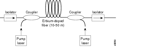
The EDFA (erbium-doped fiber amplifier) is a key enabling technology that extends the range of DWDM networks. Erbium is a rare-earth element that, when excited, emits light around 1.54 micrometers—the low-loss wavelength for optical fibers used in DWDM. Light at 980 nm or 1480 nm is injected into the fiber using a pump laser. This injected light stimulates the erbium atoms to release their stored energy as additional 1550-nm light. As this process continues down the fiber, the signal on the fiber grows stronger. The spontaneous emissions in the EDFA also add noise to the signal, which is a limiting factor for an EDFA. Figure 5-1 shows a simplified diagram of an EDFA.
Figure 5-1 Erbium-Doped Fiber Amplifier Design
The key performance parameters of optical amplifiers are gain, gain flatness, noise level, and output power. EDFAs are typically capable of gains of 30 dB or more and output power of 17 dBm or more. The target parameters for an EDFA, however, are low noise and flat gain. Gain should be flat because all signals must be amplified uniformly. While the signal gain provided with EDFA technology is inherently wavelength-dependent, it can be corrected with gain flattening filters. Such filters are often built into modern EDFAs.
Low noise is a requirement because noise, along with signal, is amplified. Because this effect is cumulative, and cannot be filtered out, the signal-to-noise ratio is a limiting factor in the number of amplifiers that can be concatenated and, therefore, the end-to-end reach of optical signals. That is because the optical amplifier merely amplifies the signals and does not perform the 3R functions (reshape, retime, retransmit).
Note
About Variable Optical Attenuation
Optical attenuation is often needed to equalize all DWDM channel powers in an amplified ring network. In a ring network, the pass through channels are typically weaker than the added channels. To equalize the channel powers, the added channel powers are attenuated down to the power level of the pass through channels. Power equalization is needed in an amplified network because of the input power limitation of the EDFAs and to simplify network management.
The Cisco ONS 15530 supports two types of variable optical attenuation, per channel and per band. Per channel attenuation equalizes the channel powers on a channel-by-channel basis, while the per band attenuation achieves equalization by attenuating channels on a band-by-band basis.
VOA Modules
Variable optical attenuation on the Cisco ONS 15530 is provided by two types of VOA modules:
•
•
The VOA modules are half-height modules inserted into a carrier motherboard installed in a Cisco ONS 15530 chassis slot.
PB-OE Modules
The PB-OE module selects and attenuates one or two specific four-channel bands and passes the remaining bands to be attenuated by another PB-OE module, by a WB-VOA module, or not attenuated at all. After the bands are attenuated, they are merged back together and sent out on the trunk fiber. The Cisco ONS 15530 supports eight single band PB-OE modules (one for each four-channel band) and four dual band PB-OE modules (for bands AB, CD, EF, and GE).
Table 5-1 lists the optical specifications for the PB-OE modules.
A single band PB-OE module accepts an incoming signal containing more than one band. The band are split by an optical band filter into two components. One component is attenuated and the other component can be passed to an another module where it can be attenuated and passed back to the original PB-OE module. The PB-OE module then recombines the two equalized components and sends it out on the trunk fiber.
Figure 5-2 shows a logical view of a single band PB-OE module combined with a single WB-VOA module for pass through band attenuation. You can also combine a PB-OE module with other PB-OE modules in a cascaded fashion.
Figure 5-2 Single Band PB-OE Module and Single WB-VOA Module Example
If a band pair has to be attenuated, use a dual band PB-OE module. When more than two add bands are to be attenuated, multiple PB-OE modules and WB-VOA modules can be cascaded. The dual band PB-OE supports band pairs AB, CD, EF, and GH.
Figure 5-3 shows a logical view of a dual band PB-OE module and single WB-VOA module combination. The single WB-VOA module attenuates the signal passed out from the dual PB-OE module.
Figure 5-3 Dual Band PB-OE Module and Single WB-VOA Module Example
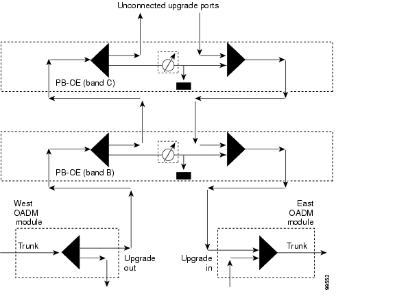
The PB-OE modules can also be use to provide an optical seam that terminates unused bands in a meshed ring topology. Unlike a hubbed ring network, the unused and dark channels in a meshed ring topology are not terminated by any OADM module anywhere in the network. If optical amplifiers are used in a meshed ring network, the EDFA-generated noise corresponding to the unused channels or bands is circulated in the ring and amplified by the EDFAs. If the loss around the ring is less than the gain around the ring, then power oscillations can occur, leading to network instability. An optical seam terminates all unused and dark channels and eliminates potential network instability due to power oscillations. Figure 5-4 shows an example of an optical seam at network site with two pass through bands, band B and band C. The optical seam consists of a band B PB-OE module cascaded with a band C PB-OE module (to allow bands B and C to pass through) and with the attenuation set to a minimum level. The upgrade ports of the band C PB-OE module are unconnected to terminate the unused bands.
Figure 5-4 Optical Seam Example
WB-VOA Modules
The Cisco ONS 15530 supports two types of WB-VOA modules: single and dual. A single WB-VOA module accepts an optical signal and attenuates all frequencies within that signal. The signal can contain a single channel, such as the OSC, a band of channels, or the entire trunk signal.
A dual WB-VOA module consists of two WB-VOA units combined into a single module. Each WB-VOA unit accepts an optical signal and attenuates all frequencies within that signal. The two WB-VOA units function independently of each other. The dual WB-VOA module provides more attenuator ports when space in a shelf is limited.
Table 5-2 lists the optical specifications for the WB-VOA modules.
Table 5-2 WB-VOA Optical Specifications
Maximum attenuation
30 dB
30 dB
Minimum attenuation resolution
0.1 dB
0.1 dB
Minimum attenuation
1.7 dB
1.7 dB
You can use WB-VOA modules for the following types of attenuation:
•
•
•
Amplified Network Planning Considerations
When planning an amplified network topology, you need to consider the following:
•
•
•
Optical Power Budget
Optical power budgets, or link loss budgets, are a critical part of planning an optical network. In general, there are many factors that can result in optical signal loss. The most obvious of these is the distance of the fiber itself. Also, the number of nodes in a network topology is a significant contributor to optical loss.
The key to precise optical power budget calculation is to get an accurate reading on the fiber using an optical time domain reflectometer (OTDR). Using an OTDR, you can obtain the following information about a span:
•
•
•
•
The goal in calculating optical loss is to ensure that the total loss does not exceed the span budget. The following are typical values for the main elements in a span:
•
•
•
It is also important to ensure that the client side or tributary equipment does not overload the local receive laser of the DWDM equipment. This means that the client or tributary equipment must operate within the specifications of the DWDM client interface.
OSNR
Besides the signal itself, optical amplifiers boost the entire input, including noise. The effect is cumulative through the network. The OSNR (optical signal-to-noise ratio) can become so low that a clear signal is not correctly decoded at the receiving end. At this point the signal must be regenerated.
Chromatic Dispersion
Chromatic dispersion occurs because different wavelengths propagate at different speeds.It can result in signal power spread and can reduce receiver sensitivity.
Amplified Network Planning Guidelines
This section describes the guidelines for planning a Cisco ONS 15530 amplified network.
Receive Power Levels
Receiver power levels for individual transponder line cards and ITU trunk cards should be within the power range defined by minimum receiver sensitivity and maximum receiver overload for each card. Depending on network configuration characteristics, such as dispersion and OSNR, apply the proper penalties to the minimum receiver sensitivity.
Optical Component Gain or Loss
Use the statistical gain or loss, determined by mean and variance values, for optical components in the network, such as OADM modules, connectors, and EDFAs. The loss for OADM modules should be based on measured data, and the gain should be based on the gain flatness specification (+/- 0.75 dB) of the Cisco ONS 15501 EDFA. The gain or loss of optical components should be accumulated in a statistical manner, such that the mean and variance of the total gains and losses is the sum of individual means and variances. The maximum gain or loss of an aggregate of optical components is equal to the mean plus three times the standard deviation (sigma), and the minimum gain or loss is equal to the mean minus three times the standard deviation.
EDFA Input Power Limits
The maximum total input power to a Cisco ONS 15501 EDFA is 0 dBm and the minimum total input power is -29 dBm.
OSNR
Use the following equation to compute the OSNR:
OSNRout = -10*log(10-OSNRin/10 + 6.33*10-6 * 10-Pin/10)
where OSNRin and Pin are the OSNR and input power, respectively, of the signal at the input of the EDFA, and OSNRout is the OSNR of the signal at the output of the EDFA.
The signal OSNR at the receiver should be higher than the minimum OSNR required for the particular card type and the data bit rate, with the proper penalties for dispersion depending on network configuration.
The above OSNR calculations can be carried out manually to verify the OSNR of individual optical channels. However, we recommend that a network design tool, such as Metro Planner, be used to validate all amplified network designs.
Channel Power Equalization
Amplified networks require that all channel powers be equalized in the network. There are two channel equalization options for Cisco ONS 15530 and Cisco ONS 15540 networks: per-channel and per-band equalization.
In the per-channel option, a WB-VOA module is placed between each transmitting ITU laser and the OADM module. The WB-VOA module attenuation value is set individually so that all channels added at the OADM module are equal in power on the outgoing trunk.
Alternatively, the added channels can be equalized on a per-band basis. The PB-OE modules and WB-VOA modules can be used for this purpose. In this case, the added bands are demultiplexed, separately attenuated, and multiplexed back together by PB-OE modules placed at the OADM module out-going trunk. The pass through bands can also be attenuated by the WB-VOA modules connected to the pass through path of the PB-OE modules.
For more information on the PB-OE modules and WB-VOA modules, see the "PB-OE Modules" section and the "WB-VOA Modules" section.
Dispersion Limits
Table 5-3 lists the dispersion limits, in the absence of DCUs (dispersion compensation units), of various components on the Cisco ONS 15530 and the Cisco ONS 15540.
DCUs
DCUs (dispersion control units) can be used in networks that exceed the dispersion limit of the transmitters. There are three types of Cisco ONS 15216 DCUs that are available: -350 ps/nm, -750 ps/nm, and -1150 ps/nm. DCUs should be placed where total power is low, for example, at the input to a preamplifier or just before an OADM module input trunk. DCUs should be placed such that any span of half the dispersion limit or more should be compensated to a value close to zero, and that the residual dispersion at the receiver is within the dispersion limit.
We recommend the use of a network design tool, such as Metro Planner, for the validation of DCUs in amplified network designs for Cisco ONS 15530 and Cisco ONS 15540 networks.
Fiber Nonlinearity
To avoid undesirable nonlinear effects, the maximum allowed channel power in ITU-652 compliant fibers must be limited in the network.
Maximum per-channel power for 10 Gbps channels is 2 dBm when there are at most three post-amplifiers, and 0 dBm when there are at most five post-amplifiers.
Maximum per-channel power for 2.5 Gbps channels is 5 dBm when there are at most five post-amplifiers.
Other types of fibers, such as ZSDF, LEAF and Truewave are not supported by these rules and must be treated separately as special cases.
OSC
The OSC (Optical Supervisory Channel) is a 1562-nm node-to-node communication channel. Because it is within the C-band range, it is also amplified by the Cisco ONS 15501 EDFA. All the rules for data channels, such as receiver power levels, OSNR, optical gains and losses, and dispersion, also apply to the OSC.
![]()
![]()
![]()
![]()
![]()
![]()
![]()
![]()
Posted: Sat Jul 1 02:06:49 PDT 2006
All contents are Copyright © 1992--2006 Cisco Systems, Inc. All rights reserved.
Important Notices and Privacy Statement.