|
|

Table Of Contents
Configuring Trunk and Uplink Card Interfaces
Configuring 2.5-Gbps ITU Trunk Card Interfaces
Displaying the 2.5-Gbps ITU Trunk Card Interface Configuration
Configuring 10-Gbps ITU Trunk Card Interfaces
Displaying the 10-Gbps ITU Trunk Card Interface Configuration
Configuring 10-Gbps Uplink Card Interfaces
Displaying the 10-Gbps Uplink Card Interface Configuration
Displaying the Cross Connection Configuration
Displaying the Alarm Threshold Configuration
Configuring Trunk and Uplink Card Interfaces
This chapter describes how to configure 2.5-Gbps ITU trunk cards, 10-Gbps ITU trunk cards, and 10-Gbps uplink cards on the Cisco ONS 15530. This chapter includes the following sections:
•
Configuring 2.5-Gbps ITU Trunk Card Interfaces
•
•
•
•
Note
Configuring 2.5-Gbps ITU Trunk Card Interfaces
To configure the 2.5-Gbps ITU trunk card interface, perform the following tasks, beginning in global configuration mode:
Step 1
Switch(config)# interface waveethernetphy slot/0
Switch(config-if)#
Selects the interface to configure and enters interface configuration mode.
Step 2
Switch(config-if)# laser frequency number
Selects one of the two frequencies in GHz supported by the laser. The default is the lower frequency for the 2.5-Gbps ITU trunk card. (Optional)
Step 3
Switch(config-if)# [no] loopback [facility | terminal]
Enables or disables internal loopback for testing and defect isolation. (Optional)
Step 4
Switch(config-if)# [no] laser control safety enable
Enables or disables laser safety control.
Step 5
Switch(config-if)# [no] laser shutdown
Turns the laser on and off. (Optional)
Note
Step 6
Switch(config-if)# [no] cdl defect-indication force hop-endpoint
Enables or disables hop endpoint for in-band message channel defect indications when APS is not configured (Optional).
Step 7
Switch(config-if)# no shutdown
Enables the interface.
Step 8
Switch(config-if)# exit
Switch(config)
Returns to global configuration mode.
Step 9
Switch(config)# interface wavepatch slot/0/0
Switch(config-if)#
Selects the interface to configure and enters interface configuration mode.
Step 10
Switch(config-if)# optical threshold power receive {low | high} {alarm | warning} value [severity {critical | major | minor | not alarmed | not reported}]
Specifies the optical power receive threshold value in units of 0.1 dBm. The default values are as follows:
Low alarm: -28 dBm
Low warning: -26 dBm
High warning: -10 dBm
High alarm: -8 dBm
Alarm severity: major
Warning severity: not alarmed
Step 11
Switch(config-if)# [no] shutdown
Enables or disables the interface.
Repeat Step 9and Step 11 on wavepatch slot/0/1 for splitter 2.5-Gbps ITU trunk cards.
Caution
Note
Example
The following example shows how to configure 2.5-Gbps ITU trunk card waveethernetphy interfaces:
Switch(config)# interface waveethernetphy 10/0Switch(config-if)# cdl defect-indication force hop-endpointSwitch(config-if)# no shutdownDisplaying the 2.5-Gbps ITU Trunk Card Interface Configuration
To display the configuration of 2.5-Gbps ITU trunk card interfaces, use the following EXEC command:
show interfaces {waveethernetphy slot/0 | wavepatch slot/0/port}
Displays the interface configuration.
Examples
The following example shows how to display the configuration of a waveethernetphy interface:
Switch# show interfaces waveethernetphy 1/0WaveEthernetPhy1/0 is up, line protocol is upChannel: 1 Frequency: 192.1 Thz Wavelength: 1560.61 nmActive Wavepatch : Wavepatch1/0/0Splitter Protected : NoSignal quality : GoodReceive power level : -6.45 dBmLaser shut down : NoOsc physical port : NoWavelength used for inband management: NoLoopback not setConfigured threshold Group: NoneCDL HEC error count: 0CRC error count: 0Code violation and running disparity error count( 64b66b cvrd): 0Defect Indication Status : upConfigured Node Behavior : Hop TerminatingCurrent Node Behavior : Hop TerminatingDefect Indication Receive : FDI-H FDI-EDefect Indication Transmit : BDI-HTx Frames sent to N/W : 218707020912Tx Frames rcvd from Client : 0Tx CRC Errors : 0Tx HEC Errors : 0Tx QuadPHY sybl Errs : 4257380395Tx Dropped Frames : 0Tx Oversize Frames : 0Tx Undersize Frames : 0Tx Idle Frames from Fabric : 0Tx Generated CDL Idle Frames : 218720041509(having an SII of 255)Rx Frames rcvd from N/W : 218719304600Rx Frames sent to Client : 647Rx CRC Errors : 0Rx HEC Errors : 0Rx MII (Decoder) Errors : 0Rx Dropped Frames : 0Rx Oversize Frames : 0Rx Undersize Frames : 0Rx Total Drpd Idle Frames : 218719303953Rx Dropped CDL Idle Frames : 218719301229(having an SII of 255)Last clearing of "show interface" counters neverHardware is data_enabled_portSwitch#sh int wavepatch 1/0/0Wavepatch1/0/0 is up, line protocol is upReceiver power level: -6.46 dBmOptical threshold monitored for : Receive Power (in dBm)Threshold exceeded for : High Warning and High AlarmLow alarm value = -28.0 (default)Low Alarm Severity = majorLow warning value = -26.0 (default)Low Warning Severity = not alarmedHigh alarm value = -8.0 (default)High Alarm Severity = majorHigh warning value = -10.0 (default)High Warning Severity = not alarmedHardware is passive_portThe following example shows how to display the configuration of a wavepatch interface:
Switch# show interfaces wavepatch 1/0/0Wavepatch1/0/0 is up, line protocol is upReceiver power level: -6.46 dBmOptical threshold monitored for : Receive Power (in dBm)Threshold exceeded for : High Warning and High AlarmLow alarm value = -28.0 (default)Low Alarm Severity = majorLow warning value = -26.0 (default)Low Warning Severity = not alarmedHigh alarm value = -8.0 (default)High Alarm Severity = majorHigh warning value = -10.0 (default)High Warning Severity = not alarmedHardware is passive_portConfiguring 10-Gbps ITU Trunk Card Interfaces
To configure the 10-Gbps ITU trunk card interface, perform the following tasks, beginning in global configuration mode:
Step 1
Switch(config)# interface waveethernetphy slot/0
Switch(config-if)#
Selects the interface to configure and enters interface configuration mode.
Step 2
Switch(config-if)# [no] loopback [facility | terminal]
Enables or disables internal loopback for testing and defect isolation. (Optional)
Step 3
Switch(config-if)# [no] laser shutdown
Turns the laser on and off. (Optional)
Note
Step 4
Switch(config-if)# [no] cdl defect-indication force hop-endpoint
Enables or disables hop endpoint for in-band message channel defect indications when APS is not configured. (Optional)
Step 5
Switch(config-if)# no shutdown
Enables the interface.
Step 6
Switch(config-if)# exit
Switch(config)
Returns to global configuration mode.
Step 7
Switch(config)# interface wavepatch slot/0/0
Switch(config-if)#
Selects the interface to configure and enters interface configuration mode.
Step 8
Switch(config-if)# optical threshold power receive {low | high} {alarm | warning} value [severity {critical | major | minor | not alarmed | not reported}]
Specifies the optical power receive threshold value in units of 0.1 dBm. The default values are as follows:
Low alarm: -22 dBm
Low warning: -20 dBm
High warning: -10 dBm
High alarm: -8 dBm
Alarm severity: major
Warning severity: not alarmed
Step 9
Switch(config-if)# [no] shutdown
Enables or disables the interface.
Repeat Step 7 and Step 9 on wavepatch slot/0/1 for splitter 10-Gbps ITU trunk cards.
Caution
Note
Example
The following example shows how to configure 10-Gbps ITU trunk card waveethernetphy interfaces:
Switch(config)# interface waveethernetphy 10/0Switch(config-if)# cdl defect-indication force hop-endpointSwitch(config-if)# no shutdownDisplaying the 10-Gbps ITU Trunk Card Interface Configuration
To display the configuration of 10-Gbps ITU trunk card interfaces, use the following EXEC command:
show interfaces {waveethernetphy slot/0[.subinterface] | wavepatch slot/0/port}
Displays the interface configuration.
Examples
The following example shows how to display the configuration of a waveethernetphy interface:
Switch# show interfaces waveethernetphy 10/0WaveEthernetPhy10/0 is down, line protocol is downChannel:30 Frequency:195.7 Thz Wavelength:1531.90 nmActive Wavepatch :Wavepatch10/0/1Splitter Protected :NoSignal quality :Loss of lockReceive power level :-35.0 dBmLaser Bias Current :91 mALaser Temperature :31.0 degree CLaser shut down :NoOsc physical port :NoWavelength used for inband management:NoLoopback not setConfigured threshold Group:NoneCDL HEC error count:0Number of times SF threshold exceeded:0Number of times SD threshold exceeded:0CRC error count:0Number of times SF threshold exceeded:0Number of times SD threshold exceeded:0Code violation and running disparity error count( 64b66b cvrd):0Number of times SF threshold exceeded:0Number of times SD threshold exceeded:0Defect Indication Status :upConfigured Node Behavior :NoneCurrent Node Behavior :Path TerminatingDefect Indication Receive : NoneDefect Indication Transmit :BDI-HTotal Tx Frames Sent to N/W: 0Tx Gen CDL Idle Frame: 1843017892Rx Frames rcvd from N/W: 0Rx CRC Errors: 0Rx HEC Errors: 0Rx XGMII Errors: 0Rx IPG drpd pkts: 0Rx Idle Packets : 0Rx Oversize Frames : 0Rx Undersize Frames : 0Rx SII mismatch drpd data Frames : 0Rx SII mismatch drpd idle Frames : 0Last clearing of "show interface" counters neverHardware is data_enabled_portThe following example shows how to display the configuration of a waveethernetphy subinterface:
Switch# show interfaces waveethernetphy 10/0.1WaveEthernetPhy10/0.1 is down, line protocol is downTx Frames Sent to N/W: 0Tx HEC Errors: 0Tx CRC Errors: 0Tx QuadPHY sybl Errs: 55688870321Tx Dropped Frames: 0Tx Oversize Frames: 0Tx Undersize Frames: 0Tx Rcvd Idle Packets: 0Rx Frames Sent to Clnt: 0Rx FIFO full drpd pkts: 0Rx Gen Idle pkt cnt: 0Last clearing of "show interface" counters neverHardware is data_enabled_portThe following example shows how to display the configuration of a wavepatch interface:
Switch# show interfaces wavepatch 3/0/0Wavepatch3/0/0 is up, line protocol is upReceiver power level:-9.86 dBmOptical threshold monitored for :Receive Power (in dBm)Threshold exceeded for :High WarningLow alarm value = -22.0 (default)Low Alarm Severity = majorLow warning value = -20.0 (default)Low Warning Severity = not alarmedHigh alarm value = -8.0 (default)High Alarm Severity = majorHigh warning value = -10.0 (default)High Warning Severity = not alarmedHardware is passive_portConfiguring 10-Gbps Uplink Card Interfaces
To configure the 10-Gbps uplink card interface, perform the following tasks, beginning in global configuration mode:
Caution
Note
Example
The following example shows how to configure 10-Gbps uplink card interfaces:
Switch(config)# interface tengigethernetphy 10/0Switch(config-if)# cdl defect-indication force hop-endpointSwitch(config-if)# no shutdownDisplaying the 10-Gbps Uplink Card Interface Configuration
To display the configuration of 10-Gbps uplink card interfaces, use the following EXEC command:
show interfaces tengigethernetphy slot/0[.subinterface]
Displays the interface configuration.
Example
The following example shows how to display the configuration of an tengigethernetphy interface:
Switch# show interfaces tengigethernetphy 3/0TenGigEthernetPhy3/0 is up, line protocol is upSignal quality :Goodlaser shut down :OffOsc physical port :NoLoopback not setWavelength used for inband management:NoConfigured threshold Group:NoneCDL HEC error count:0Number of times SF threshold exceeded:0Number of times SD threshold exceeded:0CRC error count:0Number of times SF threshold exceeded:0Number of times SD threshold exceeded:0Code violation and running disparity error count( 64b66b cvrd):0Number of times SF threshold exceeded:0Number of times SD threshold exceeded:0Defect Indication Status :upConfigured Node Behavior :NoneCurrent Node Behavior :Path TerminatingDefect Indication Receive : NoneDefect Indication Transmit : NoneTotal Tx Frames Sent to N/W: 48297Tx Gen CDL Idle Frame: 2173636535Rx Frames rcvd from N/W: 0Rx CRC Errors: 0Rx HEC Errors: 0Rx XGMII Errors: 0Rx IPG drpd pkts: 0Rx Idle Packets : 1836560218Rx Oversize Frames : 0Rx Undersize Frames : 0Rx SII mismatch drpd data Frames : 0Rx SII mismatch drpd idle Frames : 1842816773Last clearing of "show interface" counters neverHardware is data_enabled_portThe following example shows how to display the configuration of a tengigethernetphy subinterface:
Switch# show interfaces tengigethernetphy 3/0.4TenGigEthernetPhy3/0.4 is up, line protocol is upTx Frames Sent to N/W: 0Tx HEC Errors: 0Tx CRC Errors: 0Tx QuadPHY sybl Errs: 37831687439Tx Dropped Frames: 0Tx Oversize Frames: 0Tx Undersize Frames: 0Tx Rcvd Idle Packets: 0Rx Frames Sent to Clnt: 0Rx FIFO full drpd pkts: 0Rx Gen Idle pkt cnt: 0Last clearing of "show interface" counters neverHardware is data_enabled_portAbout Cross Connections
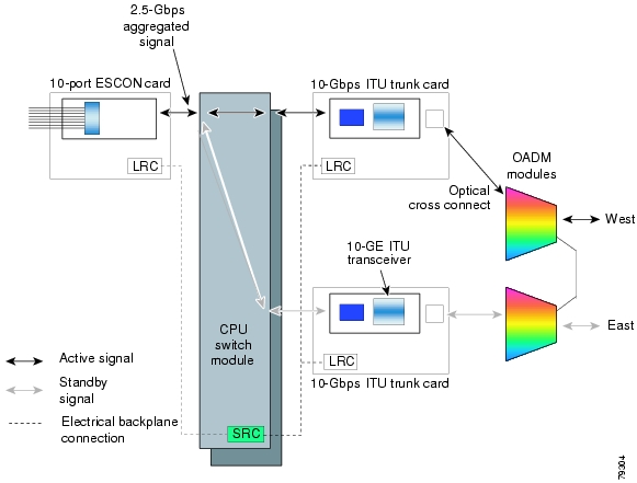
The client signal follows a path of interface optical cross connections through the Cisco ONS 15530. Figure 7-1 shows an example of cross connections. Knowing the path of a signal through the shelf helps with system management and troubleshooting.
Figure 7-1 Optical Cross Connection Example
Configuring Cross Connections
The aggregated signal from the ESCON aggregation cards and the 8-port FC/GE aggregation cards passes through the switch fabric to the 2.5-Gbps ITU trunk card, 10-Gbps ITU trunk card, or the 10-Gbps uplink card. To establish a cross connection through the switch fabric, perform the following steps, beginning in global configuration mode:
Step 1
Switch(config)# connect interface1 interface2
Creates a cross connection between two interfaces through the switch fabric.
Example
The following example shows how to configure a cross connection between an ESCON aggregation card and a 2.5-Gbps ITU trunk card:
Switch(config)# connect portgroup 2/0/0 waveethernetphy 3/0The following example shows how to configure a cross connection between an ESCON aggregation card and a 10-Gbps ITU trunk card:
Switch(config)# connect portgroup 2/0/0 waveethernetphy 3/0.1The following example shows how to configure a cross connection between an ESCON aggregation card and a 10-Gbps uplink card:
Switch(config)# connect portgroup 2/0/0 tengigethernetphy 3/0.1Displaying the Cross Connection Configuration
To display the cross connection configuration, use the following privileged EXEC command:
show connect [edge | intermediate [sort-channel | interface interface]]
Displays the signal cross connection configuration through the system.
Examples
The following example shows the cross connections within a system for an ESCON signal:
Switch# show connectIndex Client Intf Trunk Intf Kind C2TStatus T2CliStatus----- --------------- --------------- ----------- ---------- ---------15 Port3/0/0 WaveE8/0.1 Provisioned Up UpThe following example shows the cross connections within a system for a transponder signal:
Switch# show connect intermediateclient/ wave wave wdmwave client patch filter trk channel------------ ------------ ------- ------ ----- -------Trans7/0/0 Wave7/0 7/0/0* 0/0/0 0/0 257/0/1About Alarm Thresholds
You can configure thresholds on the 2.5-Gbps ITU trunk card, 10-Gbps ITU trunk card, and 10-Gbps uplink interfaces that issue alarm messages to the system if the thresholds are exceeded.
Every second, the monitoring facility updates the counters that correspond to the alarm thresholds. When the signal degrades, or fails entirely, the system issues alarms to the console. These alarms can help isolate failures in the system and in the network.
You can configure more than one threshold list on an interface. The threshold lists cannot have overlapping counters so that only one counter is set for the interface. Also, the threshold list name cannot begin with the text string "default" because the it is reserved for use by the system.
Configuring Alarm Thresholds
To configure alarm thresholds on the 2.5-Gbps ITU trunk card, 10-Gbps ITU trunk card, and 10-Gbps uplink card interfaces, perform the following steps, beginning in global configuration mode:
Step 1
Switch(config)# threshold-list name
Switch(config-t-list)#
Creates or selects the threshold list to configure and enters threshold list configuration mode.
Note
Step 2
Switch(config-t-list)# notification-throttle timer seconds
Configures the SNMP notification timer. The default value is 5 seconds. (Optional)
Step 3
Switch(config-t-list)# threshold name {cvrd | cdl hec | crc | sonet-sdh section cv | tx-crc} {failure | degrade} [index value]
Switch(config-threshold)#
Specifies a threshold type to modify and enters threshold configuration mode.
Step 4
Switch(config-threshold)# value rate value
Specifies the threshold rate value. This value is the negative power of 10 (10-n).
Step 5
Switch(config-threshold)# description text
Specifies a description of the threshold. The default value is the null string. (Optional)
Step 6
Switch(config-threshold)# exit
Switch(config-t-list)#
Returns to threshold list configuration mode.
Repeat Step 3 through Step 6 to configure more thresholds in the threshold list.
Step 7
Switch(config-t-list)# exit
Switch(config)#
Returns to global configuration mode.
Step 8
Switch(config)# interface interface
Switch(config-if)#
Selects the interface to configure and enters interface configuration mode.
Step 9
Switch(config-if)# threshold-group name
Configures the threshold list on the interface.
Table 7-1 lists the threshold error rates in errors per second.
Example
The following example shows how to create an alarm threshold list and configure that list for 10-Gbps ITU trunk card interfaces:
Switch# configure terminalSwitch(config)# threshold-list cvrd-countersSwitch(config-t-list)# threshold name cvrd degradeSwitch(config-threshold)# value rate 9Switch(config-threshold)# exitSwitch(config-t-list)# threshold name cvrd failureSwitch(config-threshold)# value rate 7Switch(config-threshold)# exitSwitch(config-t-list)# exitSwitch(config)# interface waveethernetphy 10/0Switch(config-if)# threshold-group cvrd-countersDisplaying the Alarm Threshold Configuration
To display the configuration of a threshold list and the threshold group for an interface, use the following EXEC commands:
Examples
The following example shows how to display the configuration of a threshold group:
Switch# show threshold-list cvrd-countersThreshold List Name: cvrd-countersNotification throttle timer : 5 (in secs)Threshold name : CVRD Severity : DegradeValue : 10e-9APS Trigger : Not setThreshold name : CVRD Severity : FailureValue : 10e-7APS Trigger : Not setThe following example shows how to display the threshold group information for an interface:
Switch# show interfaces waveethernetphy 10/0WaveEthernetPhy10/0 is administratively down, line protocol is downChannel: 3 Frequency: 192.3 Thz Wavelength: 1558.98 nmActive Wavepatch : Wavepatch10/0/0Splitter Protected : NoReceive power level : -8.38 dBmLaser shut down : NoOsc physical port : NoWavelength used for inband management: NoLoopback not setConfigured threshold Group(s): cvrd-countersThreshold monitored for: 64b66b cvrdSF set value: 10e-7 (1031 in 1 secs)SD set value: 10e-9 (10 in 1 secs)CDL HEC error count: 0CRC error count: 0Code violation and running disparity error count( 64b66b cvrd): 0Number of times SF threshold exceeded: 0Number of times SD threshold exceeded: 0Defect Indication Status : downConfigured Node Behavior : NoneCurrent Node Behavior : Path TerminatingDefect Indication Receive : FDI-H FDI-EDefect Indication Transmit : FDI-H FDI-EMTU Size: 10232 bytesTotal Tx Frames Sent to N/W: 0Tx Gen CDL Idle Frame: 540367537118Rx Frames rcvd from N/W: 0Rx IPG drpd pkts: 0Rx Idle Packets : 0Rx Oversize Frames : 0Rx Undersize Frames : 0Rx SII mismatch drpd data Frames : 0Rx SII mismatch drpd idle Frames : 0Last clearing of "show interface" counters neverHardware is data_enabled_portAbout Patch Connections
Because the mux/demux modules are passive devices, the Cisco ONS 15530 does not detect its optical patch connection configuration. For system management purposes, you must also configure the patch connection configuration using the CLI.
Configuring Patch Connections
To configure patch connections between link cards within the same shelf, use the following global configuration commands:
Note
Example
The following example shows how to configure the patch connections between line cards in a shelf with two OSC cards in slot 4, two OADM modules with OSC in slot 0, and a splitter 2.5-Gbps ITU trunk card or 10-Gbps ITU trunk card in slot 3:
Switch# configure terminalSwitch(config)# patch thru 0/0 thru 0/1Switch(config)# patch wave 4/0 oscfilter 0/0Switch(config)# patch wave 4/1 oscfilter 0/1Switch(config)# patch wavepatch 3/0/0 filter 0/0/1Switch(config)# patch wavepatch 3/0/1 filter 0/1/1
![]()
![]()
![]()
![]()
![]()
![]()
![]()
![]()
Posted: Wed Jun 2 13:14:40 PDT 2004
All contents are Copyright © 1992--2004 Cisco Systems, Inc. All rights reserved.
Important Notices and Privacy Statement.