|
|

Table Of Contents
Optimized Automatic Gain Control
Adding or Dropping Wavelengths
Adjusting to Span Loss Changes
Cisco ONS 15501 AC Front Panel
Cisco ONS 15501 DC Front Panel
Cisco ONS 15501 LED Alarm Definitions
Product Overview
The Cisco ONS 15501 is a low-noise, gain-flattened C-band optical EDFA (erbium-doped fiber amplifier). This guide describes how to install and operate the Cisco ONS 15501 15501-EDFA and 15501-EDFA-AC.
The Cisco ONS 15501 complements high-performance digital transmitters in topologies requiring amplification of 1550-nm optical signals.
This chapter includes the following sections:
•
Cisco ONS 15501 Applications
•
•
•
Product Description
The Cisco ONS 15501 contains erbium-doped optical fiber, optical couplers, and one or more pump lasers and isolators. An optical signal (within a range of 1530 to 1563 nm) arrives at the input connector. The 1550-nm signal travels through a length of erbium-doped fiber cable. Inside the amplifier, light from a laser at a wavelength of 980 nm (called the pump laser) is used to amplify the signal at 1550 nm. The amplified signal is coupled to the output cable for transmission to a node. In longer cable runs, up to six Cisco ONS 15501 EDFAs can be connected in tandem.
The Cisco ONS 15501 uses 980-nm pump lasers that are built to meet Bellcore TR-NWT-000468 and MIL-883D standards. With a noise figure approaching the theoretical minimum, the amplifier achieves results superior to that obtained from a 1480-nm pump laser. The 980-nm pump laser has a long lifetime, exceeding one million hours. Use of a small number of high-quality components makes the Cisco ONS 15501 a highly reliable product.
The Cisco ONS 15501 is polarization, modulation, and frequency independent, and operates in gain-controlled mode. It is optimized for different input and output powers, and it can be used as a preamplifier, inline amplifier, or booster. The unit provides excellent gain flatness for the cascading of amplifiers in DWDM applications.
The Cisco ONS 15501 is physically designed to fit into a 19-inch, 23-inch, or ETSI equipment rack, with front, middle, or rear mounting capability. It is equipped with connectors for optional monitoring either locally or remotely.
Optical Specifications
Table 1-1 lists the Cisco ONS 15501 optical specifications and Table 1-2 lists the alarms thresholds. For other technical specifications, see "Technical Specifications."
Table 1-1 Cisco ONS 15501 Optical Specifications
Wavelength range
1530 to 1563 nm
Input power range
-29 to 0 dBm
Saturated output power
17.3 ± 0.3 dBm
Noise figure
< 6.0 dB
Nominal gain
+17 dB
Gain flatness
< 1.5 dB
Settable variable gain
7 to 17 dB1
Automatic gain control accuracy
± 1.0 dB
Transient suppression response time
50 microseconds
Backward ASE2 power
< -25 dBm
PMD3
< 0.6 ps
Mode of operation
Unidirectional
Optical return loss
> 27 dB
Input and output isolation
> 30 dB
Polarization sensitivity
< 0.5 dB
Tap ratio for output monitoring port
1 percent or -20 dB
1 Gain flatness is <1.5 dB for 13 to 17 dB; <2.0 dB for 7 to 13 dB.
2 ASE = amplified spontaneous emission
3 PMD = polarization mode dispersion
Table 1-2 Alarm Thresholds
Optical input mean
-10
-10
0
Optical input trigger
0
20
20
Signal mean
-6
0
0
Signal trigger
0
17.5
18
Gain mean1
7
17.5
17.5
Gain trigger
0
1
2
Temp mean
20
30
40
Temp trigger
20
25
30
1 Gain mean is the only settable parameter that affects system performance.
Some attributes (optical input, optical output, temperature, and gain) allow alarm trigger points to be set on them. The alarms are triggered, or asserted, when the measured value crosses the value of Mean ± Trigger. Once triggered the alarm is cleared only when the measured value is at Mean ± 90% of Trigger. This approach builds a hysteresis window of 10% of trigger value. If chattering is noted for one of the alarms, increase the trigger value (so that the hysteresis is bigger) to eliminate the alarm chatter.
Key Features
The Cisco ONS 15501 has the following key features:
•
•
•
•
•
•
•
Constant Gain Flatness
The Cisco ONS 15501 is a constant gain amplifier. It does not deliver a constant output, but rather ensures that the output energy spectrum is gain-flattened irrespective of input power (up to the maximum allowed). If a channel is removed, the output level drops at the wavelength that is removed, but the remaining energy spectrum remains nearly flat over its wavelength band. The gain flatness is also only minimally affected if the input signal is not flat by several decibels.
Optimized Automatic Gain Control
The Cisco ONS 15501 has a wide input power range of -29 to 0 dBm, over which it maintains gain flatness as well as a low noise figure across the entire C band. The Cisco ONS 15501 maintains a high level of precision, as well as speed, which allows it to be used as a booster, inline or preamplifier, thus reducing sparing expenses. The constant gain and noise figure capabilities of the Cisco ONS 15501 make network designs simpler and more predictable.
The lower gain available in the Cisco ONS 15501, combined with its ability to handle input signal powers of up to 0 dBm, also enables the network designer to achieve much higher OSNR (optical signal-to-noise ratio) after cascading several EDFAs. In addition, it allows the network to expand beyond 32 wavelengths to a maximum of 128 wavelengths if necessary. The OSNR improvements of 6 dB is equivalent to a four-fold increase in the number of EDFAs that can be cascaded. Alternatively, the unit can accommodate signals with four times the data rate (for instance, OC-192 as opposed to OC-48). Thus, the limitations of higher gain EDFAs that have input powers limited to -6 dBm can be easily overcome by using the Cisco ONS 15501. Some representative figures are included in Table 1-3, assuming a flat input to the first Cisco ONS 15501.
.
Table 1-3 Relative OSNR in Cascading EDFAs
1
32
37.00 dB
31.00 dB
2
32
33.25 dB
27.25 dB
3
32
30.70 dB
24.70 dB
4
32
28.75 dB
22.70 dB
5
32
27.00 dB
21.00 dB
6
32
25.50 dB
19.50 dB
1 OSNR = optical signal-to-noise ratio
2 0 dBm total input power.
3 -6 dBm total; -21 dBm per channel.
Variable Gain
When the gain of an EDFA is fixed, the assumption is that all networks can be laid out with equally spaced EDFAs. In reality, this is rarely the case. For designs in which the spacing must be flexible, variable gain allows the network designer to tailor network requirements much more accurately. For instance, when a Cisco ONS 15501 is used as a preamplifier for receivers having an overload point of -8 dBm per wavelength, the output VOA (variable optical attenuator) can prevent overload by reducing the signal going to the receiver. Alternately, when EDFA spacing is only 10 dB, the output VOA can be enabled to avoid saturation of the next stage EDFA, ensuring that the entire network has good gain flatness and virtually consistent OSNR across all wavelengths.
The variable gain capabilities of the Cisco ONS 15501 greatly enhance the flexibility of an optical network. System operators can add or drop optical elements, such as OADM (optical add/drop multiplexer), without drastic network redesigns or costly equipment changes. When a change occurs in span loss, the adjustable gain can be used to reset the network to a better operating point.
Transient Suppression
Transients in the performance of EDFAs are inevitable whenever the number of signals or the relative power of signals change. For example, when channel rerouting or system failure (caused by a fiber cut or equipment malfunction) transfers all incoming power to a single "surviving channel," that channel momentarily experiences a higher gain, which can cause BER (bit error rate) problems due to eye-pattern closure. The amount of time required by an amplifier to recover from such a change indicates its suitability for add/drop applications.
The most important parameters in transient suppression are the recovery time and the overshoot and undershoot amplitude. The recovery time for the signal amplitude to get within 10% of the "steady state" amplitude after the switching event is referred to as the transient suppression time. Smaller values are desirable. From a 10 dB change in power (simulating the adding or dropping of 29 out of 32 channels present), the Cisco ONS 15501 never exceeds 100 microseconds and is typically below 50 microseconds. The Cisco ONS 15501 can respond to the most drastic power changes with overshoots or undershoots of less than 1 dB.
Low Noise Figure
The low noise characteristics of the Cisco ONS 15501 allow over six amplifiers to be cascaded and still achieve an excellent OSNR at input powers as low as -21 dBm per channel. This enables seamless migration to higher speeds beyond OC-48 and to a larger number of channels.
High Maximum Input Power
The high maximum optical power of the Cisco ONS 15501 increases the number of wavelengths that can potentially be routed to it. The higher input power range available can be used to increase the number of wavelengths to 128 from 32, without having any spectral gain tilt effects.
Network Management
The Cisco ONS 15501 supports SNMP, and it has a console port to facilitate setup and monitoring. With a customer-supplied network monitor and the provided MIB file, all monitorable and settable parameters are available remotely.
Cisco ONS 15501 Applications
The Cisco ONS 15501 supports the following applications:
•
•
•
•
Point-to-Point Topologies
In a metropolitan point-to-point DWDM network, the Cisco ONS 15501 can function as a pre-, post-, and/or inline amplifier. Most metropolitan point-to-point DWDM networks require post-amplifiers, but if a given span length exceeds the unit gain (>17 dB), a preamplifier may also be required to handle the optical link loss budget. When the span length greatly exceeds 17 dB, an inline amplifier might also be required.
Because of the wide input power range (-29 to 0 dBm) of the Cisco ONS 15501, trunk attenuation is typically also necessary, especially when the unit is used as a post-amplifier. For instance, when the per channel output power from the node is -5 dBm in a 32-channel system, the total output power from the node is +10 dBm. Thus, at least 10 dB of trunk attenuation is required directly preceding the amplifier.
The Cisco ONS 15501 can also be tuned to meet post- or inline amplification input power requirements.
Assuming that the typical per channel power levels in a point-to-point network are identical at the source node, and that there are fewer than four amplifiers between source and destination nodes, it is not necessary to maintain per channel power equalization to satisfy each amplifier's total input power requirement and maintain acceptable OSNR for each channel.
Ring Topologies
An amplified ring topology requires more fine-tuning of power for each channel or band. Figure 1-1 illustrates a hubbed ring network utilizing counter-clockwise signal transmission. All bands (A, B, C and D) are transmitted from node 1. Node 2 terminates and transmits bands A and B; node 3 terminates and transmits band C; and node 4 terminates and transmits band D.
Figure 1-1 Power Equalization in an Amplified Ring Network
In general, EDFAs in a ring topology should be placed so they maintain the power level at the receiver, as well as the OSNR, of each channel. In this case, EDFAs serving as postamplifiers are located at nodes 2 and 4.
At node 2, the input power level of the EDFA is much higher than the input power level of the pass-through band (bands C and D), due to the added power from bands A and B. If trunk attenuation is employed directly before the EDFA at node 2 to keep the unit's total input power within the required range, the power levels of both the add bands (bands A and B) and the pass-through bands (bands C and D) are attenuated equally. As a result, the power level of the pass-through bands is much lower than that of the add bands. This significantly degrades the OSNR of the pass-through bands, and in cases where there are more than two EDFAs in the ring, some of the channels in the ring will not meet OSNR requirements.
To solve this problem, optical power attenuation should be applied on a per channel or per band basis. More attenuation is typically required for the add bands than for the pass-through bands. At the EDFA input, the individual channel or band power levels should be equalized as close as possible to the maximum per channel input power level (for example, -15 dBm in a 32-channel system). This process of optical power equalization is necessary to obtain better OSNR.
Inserting attenuation devices such as VOAs (variable optical attenuators) between the OADM (optical add/drop multiplexer) and the transmitter allows optical power management of individual channels. Per band power management at the trunk line, between the OADM and the EDFA, is also an effective method. The Cisco ONS 15501 is capable of supporting either approach, and its wide input range (-29 to 0 dBm) makes it an ideal amplifier for a broad array of ring network designs.
Adding or Dropping Wavelengths
Automatic gain control reacts to the adding or dropping of wavelengths in a network, without requiring power equalization tuning. The fast response of the Cisco ONS 15501 reduces the impact of adding or dropping channels, and prevents BER hits.
Adjusting to Span Loss Changes
It is typically necessary to adjust gain and attenuation values both for trunk attenuation and channel or band power equalization.
Cisco ONS 15501 AC Front Panel
Figure 1-2 shows the Cisco ONS 15501 front panel. The front panel provides an all-front access interface (fibers, power, alarm contact, and management) that complies with international standards. Table 1-4 explains the front panel features.
Figure 1-2 Cisco ONS 15501 AC Front Panel
Table 1-4 Cisco ONS 15501 AC Front Panel Features
Output monitor (connector)
Provides spectrum monitoring of the Cisco ONS 15501 output and uses an SC/UPC type bulkhead connector. (A shutter automatically closes when the cable is removed.)
Output (connector)
Provides output to an optical fiber cable and uses an SC/UPC type standard connector. (A shutter automatically closes when the cable is removed.)
Input (connector)
Provides optical fiber cable access to the input of the Cisco ONS 15501 and uses an SC/UPC type standard connector. (This is a nonshuttered connector.)
Fail (red LED)
Indicates a major failure, such as the pump laser, power supply, or the temperature level.
Power (green LED)
Indicates the unit is receiving normal operating power.
LOS (loss of signal) (yellow LED)
Indicates a loss of input signal when the input signal falls below the LOS threshold.
RS-232 (connector)
Provides a console port for local monitoring of the Cisco ONS 15501 and uses a straight serial, DB-9 type female connector that ships with the product. (See "Connector Pinouts.") This port should only be used for the evaluation of the unit by a trained technician. It is not designed for permanent connection.
Alarm out (connector)
Provides four pairs of dry contacts for an optional external alarm-monitoring system. Normally has closed contacts and uses an RJ-45 type connector. (See "Connector Pinouts.")
LAN (connector)
Provides Ethernet access for connecting to a remote SNMP monitoring location, and contains two LEDs. The left LED (green) indicates that an Ethernet connection is established. The right LED (yellow) indicates that a signal is being transmitted to the Ethernet. It uses an RJ-45 type connector.
ESD (connector)
Provides a socket for an anti-ESD wrist strap.
Cisco ONS 15501 DC Front Panel
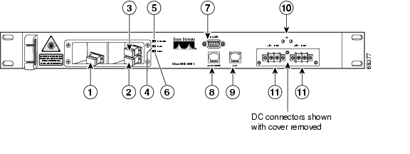
Figure 1-3 shows the Cisco ONS 15501 DC front panel. The front panel provides an all-front access interface (fibers, power, alarm contact, and management) that complies with international standards. Table 1-5 explains the front panel features.
Figure 1-3 Cisco ONS 15501 DC Front Panel
Table 1-5 Cisco ONS 15501 DC Front Panel Features
Output monitor (connector)
Provides spectrum monitoring of the Cisco ONS 15501 output and uses an SC/UPC type bulkhead connector. (A shutter automatically closes when the cable is removed.)
Output (connector)
Provides output to an optical fiber cable and uses an SC/UPC type standard connector. (A shutter automatically closes when the cable is removed.)
Input (connector)
Provides optical fiber cable access to the input of the Cisco ONS 15501 and uses an SC/UPC type standard connector. (This is a nonshuttered connector.)
Fail (red LED)
Indicates a major failure, such as the pump laser, power supply, or the temperature level.
Power (green LED)
Indicates the unit is receiving normal operating power.
LOS (loss of signal) (yellow LED)
Indicates a loss of input signal when the input signal falls below the LOS threshold.
RS-232 (connector)
Provides a console port for local monitoring of the Cisco ONS 15501 and uses a DB-9 type female connector that ships with the product. (See "Connector Pinouts.") This port should only be used for the evaluation of the unit by a trained technician. It is not designed for permanent connection.
Alarm out (connector)
Provides four pairs of dry contacts for an optional external alarm-monitoring system. Normally has closed contacts and uses an RJ-45 type connector. (See "Connector Pinouts.")
LAN (connector)
Provides Ethernet access for connecting to a remote SNMP monitoring location, and contains two LEDs. The left LED (green) indicates that an Ethernet connection is established. The right LED (yellow) indicates that a signal is being transmitted to the Ethernet. It uses an RJ-45 type connector.
Frame ground attachment
Provides tapped-screw mounting holes for attaching a frame ground lug and wiring.
Dual-circuit DC power input
Provides two sets of DC input barrier strip terminals. The right-hand strip terminal is for the primary DC power wiring; the left-hand strip terminal is for an optional backup DC power source. The left screw terminal of each strip is for -48 VDC; the right screw terminal is for the return path.
Cisco ONS 15501 LED Alarm Definitions
The Cisco ONS 15501 front panel has three LEDs:
•
–
–
–
•
–
–
•
–
–
![]()
![]()
![]()
![]()
![]()
![]()
![]()
![]()
Posted: Thu Jun 24 09:55:01 PDT 2004
All contents are Copyright © 1992--2004 Cisco Systems, Inc. All rights reserved.
Important Notices and Privacy Statement.