|
|

The Catalyst 3900 Token Ring switch and Catalyst 5000 Token Ring switch module can be used to collapse network backbones and floor rings in classic Token Ring environments with redundantly placed source-route bridges. The use of a Catalyst Token Ring switch in this scenario improves network performance by eliminating the need for multiple bridges and by allowing the direct attachment of high-utilization devices, such as servers, front-end processors, and routers.
This section provides an example of using Catalyst Token Ring switches to replace multiple bridges in a classic Token Ring network.
This chapter provides the following information:
In your company, you have two backbone rings that service five floor rings. You have a server, router, and front-end processor attached to each of the backbone rings. Because the number of users is growing and there is an increased need to access the devices that are attached to the backbone rings, you need to improve the performance of your network. You have decided to replace one ring with a Catalyst 3900 and one with a Catalyst 5000 with a Token Ring switching module.
Figure 7-1 illustrates the initial network configuration.
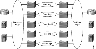
To configure your collapsed backbone network, on each switch you will need to configure a new bridge (TrBRF) as you cannot add TrCRFs to the default TrBRF, a ring (TrCRF) for each floor, as well as a TrCRF that will contain the high-utilization devices.
On the Catalyst 3900, you must configure a new bridge (TrBRF) and six new rings (TrCRFs).
To define a bridge (TrBRF), complete the following steps:
Step 1. On the Catalyst 3900 Main Menu, select Configuration. The Configuration panel is displayed.
Step 2. On the Configuration panel, select VLAN and VTP Configuration. The VLAN and VTP Configuration panel is displayed.
Step 3. On the VLAN and VTP Configuration panel, select VTP VLAN Configuration. The VTP VLAN Configuration panel is displayed.
Step 4. On the VTP VLAN Configuration panel, select Add.
Step 5. At the prompt, enter a VLAN ID of 100 .
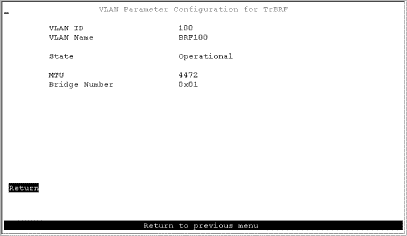
Step 6. At the prompt, select TrBRF. The VLAN Parameter Configuration for TrBRF panel (Figure 7-2) is displayed.
Step 7. On the VLAN Parameter Configuration for TrBRF panel, specify:
Step 8. Select Return to save your changes.
To define the rings (TrCRFs) for the first floor, complete the following steps:
Step 1. On the VTP VLAN Configuration panel, select Add.
Step 2. At the prompt, enter a VLAN ID of 101.
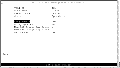
Step 3. At the prompt, select TrCRF. The VLAN Parameter Configuration for TrCRF (Figure 7-3) panel is displayed.
Step 4. On the VLAN Parameter Configuration for TrCRF panel, specify:
Step 5. Select Return to save your changes.
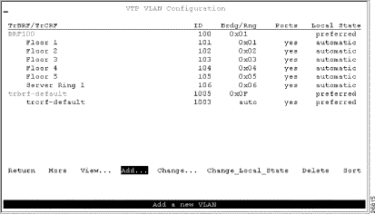
To define the TrCRFs for the remaining floors, repeat Step 1 through Step 5 and use the following values:
To define the TrCRF for the high-utilization devices, repeat Step 1 through Step 5 and use the following values:
Figure 7-4 shows the resulting VTP VLAN Configuration panel.
Next, you must assign the ports to the appropriate TrCRFs. On the Catalyst 3900, complete the following steps:
Step 1. On the VLAN and VTP Configuration panel, select Local VLAN Port Configuration. The Local VLAN Port Configuration panel is displayed.
Step 2. On the Local VLAN Port Configuration panel, select Change.
Step 3. At the prompt enter port number 1.
Step 4. Select Floor 1 from the list of possible TrCRFs. To select the TrCRF, use your arrow keys to highlight the desired TrCRF, press the space bar to select it, and press Enter to implement your change (Figure 7-5).
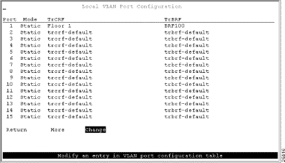
Step 5. Repeat Step 2 through Step 4 to assign the ports to the appropriate TrCRFs as follows:
| Ports | TrCRF |
|---|---|
2 | Floor 1 |
3, 4 | Floor 2 |
5, 6 | Floor 3 |
7, 8 | Floor 4 |
9, 10 | Floor 5 |
11, 12, 13 | Server Ring 1 |
Step 6. Select Return to save your changes.
If you install an external bridge to create a backup path, you introduce possible loops into your network. However, STPs prevent these loops. By default, the TrBRF runs the IBM STP. The STP run on the TrCRF can be manually configured, however, by default the TrCRF STP is determined by the bridging mode. TrCRFs with a bridging mode of SRB will run the IEEE STP and TrCRFs with a bridging mode of SRT will run the Cisco STP.
On the Catalyst 5000, you must configure a new bridge (TrBRF), 6 new rings (TrCRFs), and the STP. You have inserted the Token Ring module into slot 2 of the Catalyst 5000.
To define the bridge (TrBRF), complete the following steps:
Step 1. At the Catalyst 5000 command prompt, enter enable.
Step 2. At the enable prompt, enter set vlan 200 name brf200 type trbrf bridge 2.
Step 3. To verify the configuration of the new VLAN, enter show vlan.
The output (Figure 7-6) indicates that brf200 has been added, but it does not have any TrCRFs assigned to it yet.
VLAN Name                             Status    Mod/Ports, Vlans
---- -------------------------------- --------- ----------------------------
1    default                          active    1/1-2
200  brf200                           active
1002 fddi-default                     active
1003 trcrf-default                    active    2/1-16
1004 fddinet-default                  active
1005 trbrf-default                    active    1003
To define the ring (TrCRF) for the first floor, complete the following steps:
Step 1. At the enable prompt, enter:
set vlan 201 name Floor_1 type trcrf ring 1 parent 200 mode srb
Step 2. To verify the configuration of the new VLAN, enter show vlan.
The output (Figure 7-7) indicates that FLoor_1 has been added, but it does not have any ports assigned to it yet. It also shows that brf200 is the parent of the VLAN with the ID of 201.
VLAN Name                             Status    Mod/Ports, Vlans
---- -------------------------------- --------- ----------------------------
1    default                          active    1/1-2
200  brf200                           active    201
201  Floor_1                          active
1002 fddi-default                     active
1003 trcrf-default                    active    3/1-16
1004 fddinet-default                  active
1005 trbrf-default                    active    1003

VLAN Type  SAID       MTU   Parent RingNo BrdgNo Stp  BrdgMode Trans1 Trans2
---- ----- ---------- ----- ------ ------ ------ ---- -------- ------ ------
1    enet  100001     1500  -      -      -      -    -        0      0
200  trbrf 100200     4472  -      -      0x2    ibm  -        0      0
201  trcrf 100201     4472  100    0x01   -      -    srb      0      0
1002 fddi  101002     1500  -      0x0    -      -    -        0      0
1003 trcrf 101003     4472  1005   0xccc  -      -    srb      0      0
1004 fdnet 101004     1500  -      -      0x0    ieee -        0      0
1005 trbrf 101005     4472  -      -      0xf    ibm  -        0      0
To define the TrCRFs for the remaining floors, enter the set vlan commands as follows:
set vlan 202 name Floor_2 type trcrf ring 2 parent 200 mode srb
set vlan 203 name Floor_3 type trcrf ring 3 parent 200 mode srb
set vlan 204 name Floor_4 type trcrf ring 4 parent 200 mode srb
set vlan 205 name Floor_5 type trcrf ring 5 parent 200 mode srb
To define the TrCRF for the server ring, enter the set vlan commands as follows:
set vlan 207 name Server_Ring_2 type trcrf ring 7 parent 200 mode srb
The output (Figure 7-8) indicates that the TrCRFs have been added, but there are no ports assigned to them yet. It also shows that brf200 is the parent of the new TrCRFs.
VLAN Name                             Status    Mod/Ports, Vlans
---- -------------------------------- --------- ----------------------------
1    default                          active    1/1-2
200  brf200                           active    201, 202, 203, 204, 205, 207
201  Floor_1                          active
202  Floor_2                          active
203  Floor_3                          active
204  Floor_4                          active
205  Floor_5                          active
207  Server_Ring_2                    active
1002 fddi-default                     active
1003 trcrf-default                    active    2/1-16
1004 fddinet-default                  active
1005 trbrf-default                    active    1003


VLAN Type  SAID       MTU   Parent RingNo BrdgNo Stp  BrdgMode Trans1 Trans2
---- ----- ---------- ----- ------ ------ ------ ---- -------- ------ ------
1    enet  100001     1500  -      -      -      -    -        0      0
200  trbrf 100200     4472  -      -      0x2    ibm  -        0      0
201  trcrf 100201     4472  200    0x01   -      -    srb      0      0
202  trcrf 100202     4472  200    0x02   -      -    srb      0      0
203  trcrf 100203     4472  200    0x03   -      -    srb      0      0
204  trcrf 100204     4472  200    0x04   -      -    srb      0      0
205  trcrf 100205     4472  200    0x05   -      -    srb      0      0
207  trcrf 100207     4472  200    0x07   -      -    srb      0      0
1002 fddi  101002     1500  -      0x0    -      -    -        0      0
1003 trcrf 101003     4472  1005   0xccc  -      -    srb      0      0
1004 fdnet 101004     1500  -      -      0x0    ieee -        0      0
1005 trbrf 101005     4472  -      -      0xf    ibm  -        0      0
To assign the ports to the rings (TrCRFs), enter the set vlan commands at the enable prompt as follows:
set vlan 201 23/1-2
set vlan 202 2/3-4
set vlan 203 2/5-6
set vlan 204 2/7-8
set vlan 205 2/9-10
set vlan 207 2/11-13
The output (Figure 7-9) shows that two ports on the module are assigned to each of the five TrCRFs that represent each floor and that three ports are assigned to Server_Ring_2.
VLAN Name                             Status    Mod/Ports, Vlans
---- -------------------------------- --------- ----------------------------
1    default                          active    1/1-2
200  brf200                           active    201, 202, 203, 204, 205, 207
201  Floor_1                          active    2/1-2
202  Floor_2                          active    2/3-4
203  Floor_3                          active    2/5-6
204  Floor_4                          active    2/7-8
205  Floor_5                          active    2/9-10
207  Server_Ring_2                    active    2/11-13
1002 fddi-default                     active
1003 trcrf-default                    active    2/14-16
1004 fddinet-default                  active
1005 trbrf-default                    active    1003
By default, the TrBRF runs the IBM STP. The STP run on the TrCRFs is determined by the specified bridging mode. TrCRFs with a bridge mode of SRB will run the IEEE STP and TrCRFs with a bridge mode of SRT will run the Cisco STP.
Using the appropriate cabling, attach ports 1 and 2 of the Catalyst 3900 to the existing ring on floor 1. Repeat this for each of the floors. Then attach port 11 to the router, port 12 to the server, and port 13 to the front-end processor. Do the same for the ports on the Catalyst 5000.
You now have a faster, more efficient network that includes less hardware to maintain (Figure 7-10).
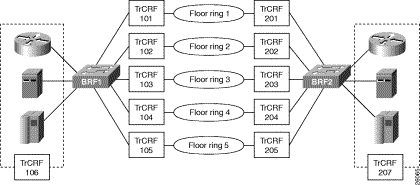
To further improve performance, if you have 16 Mbps connections and the network interface card (NIC) supports full-duplex, you can configure the ports connected to the servers to operate in FDX mode. To configure FDX:
Step 1. Select Port Configuration on the Configuration panel.
Step 2. Specify the port to which the high-utilization device is attached. In this scenario, that would be ports 11, 12, and 13.
Step 3. On the Port Configuration panel, move to the Operation Mode and select the FDX port mode.
Step 4. Select Return.
![]()
![]()
![]()
![]()
![]()
![]()
![]()
![]()
Posted: Wed Oct 2 03:51:26 PDT 2002
All contents are Copyright © 1992--2002 Cisco Systems, Inc. All rights reserved.
Important Notices and Privacy Statement.