|
|

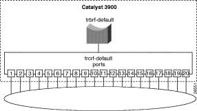
The Catalyst 3900 and the Catalyst 5000 Token Ring switching module are shipped with a default configuration that allows you to use the switch without modification in many small networks. One aspect of this default configuration is that the switch is configured as a single VLAN. However, for more complex networks, you can subdivide the Catalyst 3900 or Catalyst 5000 Token Ring switching module into multiple virtual rings (TrCRFs) that can be connected by one or more internal bridges (TrBRFs). Initially, all ports are assigned to the default ring (trcrf-default) and the default ring is associated with the default bridge (trbrf-default).
To assist you in understanding how to subdivide your switch, this chapter provides an example of configuring two additional VLANs for a Catalyst 3900.
This chapter provides the following information:
In this scenario, you have a small company that is growing. Last year, there were only 10 employees in the human resources and payroll departments. Now there are 34 employees. When there were only 10 employees, they could share a single server that contains a database of records. Now, however, each department needs a dedicated server.
Figure 6-1 illustrates the initial VLAN configuration of the Catalyst 3900.
You want to add a new ring that includes ports 1 and 2 for the employees of the Human Resources department and another ring that includes ports 3 and 4 for the employees of the Payroll department.
Only the default ring (TrCRF) can be assigned to the default bridge (TrBRF). You cannot assign new rings to the default bridge. Therefore, you must first define a new bridge (TrBRF) and then you can define the new rings and assign ports to them.
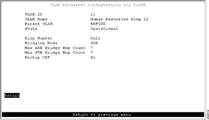
You have met with the IS department and have decided to create two new rings, with ring numbers 11 and 12, and connect them with a bridge, which will have the bridge number of 1. Because the network contains a large number of Cisco devices, you are using VTP to distribute information about the VLANs in the network. You have decided to assign the VLAN IDs as follows:
| Ring number | VLAN ID | VLAN Name |
|---|---|---|
11 | 11 | Human Resources Ring 11 |
12 | 12 | Payroll Ring 12 |
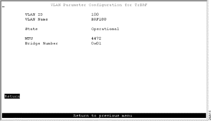
The bridge will be assigned a VLAN ID of 100 and a VLAN name of BRF100.
Microsegmenting the ring involves creating multiple rings, which means you are creating multiple VLANs. You are going to put the users and their servers in separate TrCRFs and join them using a TrBRF.
You have physically separated the servers from the users. Next, you must attach the rings and the servers to separate ports on the Catalyst 3900 switches.
On both switches, do the following:
The ports will automatically sense the speed and mode of the connection.
Next, you must define the VLANs. As determined before beginning, you will need a new TrBRF and two TrCRFs; one for the Human Resources users and their server and one for the Payroll users and their server.
To define a bridge (TrBRF), complete the following steps:
Step 1. On the Catalyst 3900 Main Menu, select Configuration. The Configuration panel is displayed.
Step 2. On the Configuration panel, select VLAN and VTP Configuration. The VLAN and VTP Configuration panel is displayed.
Step 3. On the VLAN and VTP Configuration panel, select VTP VLAN Configuration. The VTP VLAN Configuration panel is displayed.
Step 4. On the VTP VLAN Configuration panel, select Add.
Step 5. At the prompt, enter a VLAN ID of 100 .
Step 6. At the prompt, select TrBRF. The VLAN Parameter Configuration for TrBRF panel (Figure 6-2) is displayed.
Step 7. On the VLAN Parameter Configuration for TrBRF panel, specify:
Step 8. Select Return to save your changes.
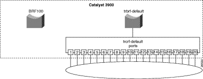
Figure 6-3 illustrates the VLAN configuration of the Catalyst 3900 after the additional bridge has been configured. Notice that no rings are assigned to it yet.
To define the ring (TrCRF) for the Human Resources users, complete the following steps:
Step 1. On the VTP VLAN Configuration panel, select Add.
Step 2. At the prompt, enter a VLAN ID of 11.
Step 3. At the prompt, select TrCRF. The VLAN Parameter Configuration for TrCRF panel (Figure 6-4) is displayed.
Step 4. On the VLAN Parameter Configuration for TrCRF panel, specify:
Step 5. Select Return to save your changes.
To define the ring (TrCRF) for the Payroll users, repeat Step 1 through Step 4 and use the following values:
Figure 6-5 illustrates the VLAN configuration of the Catalyst 3900 after the additional rings have been configured. Notice that the rings are configured and associated with the bridge, but no ports are assigned to the rings.
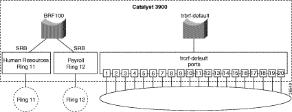
Next, you must assign the ports to the appropriate rings (TrCRFs). On the Catalyst 3900, do the following:
Step 1. On the VLAN and VTP Configuration panel, select Local VLAN Port Configuration. The Local VLAN Port Configuration panel is displayed.
Step 2. On the Local VLAN Port Configuration panel, select Change.
Step 3. At the prompt enter port number 1.
Step 4. Select Human Resources Ring 11 from the list of possible TrCRFs. To select the TrCRF, use your cursor movement keys to highlight the desired TrCRF, press the space bar to select it, and press Enter to implement the change.
Step 5. Repeat Step 2 through Step 4 for port 2.
Step 6. Again, on the Local VLAN Port Configuration panel, select Change.
Step 7. At the prompt enter port number 3.
Step 8. Select Payroll Ring 12 from the list of possible TrCRFs.
Step 9. Repeat Step 6 through Step 8 for port 4.
Step 10. Select Return to save the changes.
Figure 6-6 displays the Local VLAN Port Configuration Panel after you have made your changes.
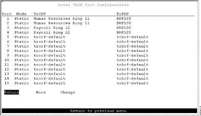
You now have a network with improved performance because the number of users per ring has been reduced and the servers have dedicated bandwidth (Figure 6-7).
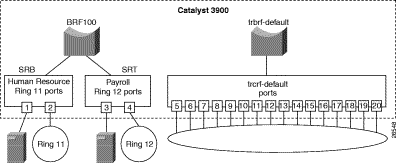
This section contains tips that may be useful in creating a configuration similar to the one in this scenario.
If you install an external bridge to create a backup path between rings 11 and 12, you introduce possible loops into your network. However, STPs prevent these loops. By default, the TrBRF runs the IBM STP. The STP run on the TrCRF can be manually configured, though. By default the TrCRF STP is determined by the bridging mode. TrCRFs with a bridging mode of SRB will run the IEEE STP and TrCRFs with a bridging mode of SRT will run the Cisco STP.
To aid in network management and network identification, we recommend that:
To further improve performance, if you have 16 Mbps connections and the server's NIC supports FDX, you can configure the ports connected to the servers to operate in FDX mode. To configure FDX:
Step 1. Select Port Configuration on the Configuration panel.
Step 2. Specify the port to which the server is attached. In this scenario, that would be either port 2 or 4.
Step 3. On the Port Configuration panel, move to the Operation Mode and select a mode of FDX port.
Step 4. Select Return.
You can create a similar configuration using two Catalyst 5000 series Token Ring switching modules. The Catalyst 5000 provides a command line interface rather than a menu-driven interface, so the steps are slightly different. This section provides an overview of the configuration steps to achieve a similar configuration using two Catalyst 5000 Token Ring modules.
To define the bridge (TrBRF), complete the following steps:
Step 1. At the Catalyst 5000 command prompt, enter enable.
Step 2. At the enable prompt, enter set vlan 100 name brf100 type trbrf bridge 1.
Step 3. To verify the configuration of the new VLAN, enter show vlan.
The output (Figure 6-8), indicates that brf100 has been added, but it does not have any TrCRFs assigned to it yet.
VLAN Name                             Status    Mod/Ports, Vlans
---- -------------------------------- --------- ----------------------------
1    default                          active    1/1-2
                                                2/1-48
100  brf100                           active
1002 fddi-default                     active
1003 trcrf-default                    active    3/1-16
1004 fddinet-default                  active
1005 trbrf-default                    active    1003
To define the ring (TrCRF) for the Human Resource users, complete the following steps:
Step 1. At the enable prompt, enter set vlan 11 name hr-ring11 type trcrf ring 11 parent 100 mode srb.
Step 2. To verify the configuration of the new VLAN, enter show vlan.
The output (Figure 6-9) indicates that hr-ring11 has been added, but it does not have any ports assigned to it yet. It also shows that brf100 is the parent of the VLAN with the ID of 11.
VLAN Name                             Status    Mod/Ports, Vlans
---- -------------------------------- --------- ----------------------------
1    default                          active    1/1-2
                                                2/1-48
11   hr-ring11                        active
100  brf100                           active    11
1002 fddi-default                     active
1003 trcrf-default                    active    3/1-16
1004 fddinet-default                  active
1005 trbrf-default                    active    1003


VLAN Type  SAID       MTU   Parent RingNo BrdgNo Stp  BrdgMode Trans1 Trans2
---- ----- ---------- ----- ------ ------ ------ ---- -------- ------ ------
1    enet  100001     1500  -      -      -      -    -        0      0
11   trcrf 100110     4472  100    0x11   -      -    srb      0      0
100  trbrf 100100     4472  -      -      0x1    ibm  -        0      0
1002 fddi  101002     1500  -      0x0    -      -    -        0      0
1003 trcrf 101003     4472  1005   0xccc  -      -    srb      0      0
1004 fdnet 101004     1500  -      -      0x0    ieee -        0      0
1005 trbrf 101005     4472  -      -      0xf    ibm  -        0      0
To define the TrCRF for the Payroll users, do the following:
Step 1. At the enable prompt, enter set vlan 12 name payroll-ring12 type trcrf ring 12 parent 100 mode srb.
Step 2. To verify the configuration of the new VLAN, enter show vlan.
The output (Figure 6-10) indicates that payroll-ring12 has been added, but it does not have any ports assigned to it yet. It also shows that brf100 is the parent of the VLAN with the ID of 12.
VLAN Name                             Status    Mod/Ports, Vlans
---- -------------------------------- --------- ----------------------------
1    default                          active    1/1-2
                                                2/1-48
11   hr-ring11                        active
12   payroll-ring12                   active
100  brf100                           active    11, 12
1002 fddi-default                     active
1003 trcrf-default                    active    3/1-16
1004 fddinet-default                  active
1005 trbrf-default                    active    1003

VLAN Type  SAID       MTU   Parent RingNo BrdgNo Stp  BrdgMode Trans1 Trans2
---- ----- ---------- ----- ------ ------ ------ ---- -------- ------ ------
1    enet  100001     1500  -      -      -      -    -        0      0
11   trcrf 100110     4472  100    0x11   -      -    srb      0      0
12   trcrf 100120     4472  100    0x12   -      -    srb      0      0
100  trbrf 100100     4472  -      -      0x1    ibm  -        0      0
1002 fddi  101002     1500  -      0x0    -      -    -        0      0
1003 trcrf 101003     4472  1005   0xccc  -      -    srb      0      0
1004 fdnet 101004     1500  -      -      0x0    ieee -        0      0
1005 trbrf 101005     4472  -      -      0xf    ibm  -        0      0
To assign the ports to the rings (TrCRFs), complete the following steps:
Step 1. At the enable prompt, enter set vlan 11 3/1-2.
Step 2. At the enable prompt, enter set vlan 12 3/3-4.
The output (Figure 6-11) shows that ports 1 and 2 on module 3 are assigned to crf11 and that ports 3 and 4 on module 3 are assigned to crf12.
VLAN Name                             Status    Mod/Ports, Vlans
---- -------------------------------- --------- ----------------------------
1    default                          active    1/1-2
                                                2/1-48
11   hr-ring11                        active    3/1-2
12   payroll-ring12                   active    3/3-4
100  brf100                           active    11, 12
1002 fddi-default                     active
1003 trcrf-default                    active    3/5-16
1004 fddinet-default                  active
1005 trbrf-default                    active    1003
By default, the TrBRF runs the IBM STP. The STP run on the TrCRFs is determined by the specified bridging mode. TrCRFs with a bridge mode of SRB will run the IEEE STP and TrCRFs with a bridge mode of SRT will run the Cisco STP.
The Catalyst 5000 Token Ring switching module considers the combination of the IBM STP at the TrBRF and the bridge mode of SRT to be incompatible. As a result, if you had configured one of the TrCRFs (for example, payroll-ring12) with a bridge mode of SRT, the Catalyst 500 Token Ring switching module would automatically block the logical port of the TrCRF that is configured for SRT. Use the show spantree command to view the state of the logical ports (Figure 6-12).
VLAN 100
Spanning tree enabled
Spanning tree type          ibm

Designated Root             00-e0-1e-2f-6c-63
Designated Root Priority    32768
Designated Root Cost        0
Designated Root Port        1/0
Root Max Age   6  sec    Hello Time 2  sec   Forward Delay 4  sec

Bridge ID MAC ADDR          00-e0-1e-2f-6c-63
Bridge ID Priority          32768
Bridge Max Age 6  sec    Hello Time 2  sec   Forward Delay 4  sec

Port,Vlan Vlan  Port-State     Cost   Priority  Fast-Start  Group-method
--------- ----  -------------  -----  --------  ----------  ------------
 1/2      100   forwarding        19        32   disabled
 11       100   forwarding        80        32   disabled
 12       100   blocking          80        32   disabled
* = portstate set by user configuration
You can then use the set spantree portstate command to change the forwarding mode of the logical port.
![]()
![]()
![]()
![]()
![]()
![]()
![]()
![]()
Posted: Wed Oct 2 03:48:09 PDT 2002
All contents are Copyright © 1992--2002 Cisco Systems, Inc. All rights reserved.
Important Notices and Privacy Statement.