|
|

Table Of Contents
Configuring the Single Subnet (Bridge) Mode
Configuring the Secure (Router) Mode
Creating Fault-Tolerant HSRP Configurations
Configuring Content Switching
This chapter describes how to configure content switching and contains these sections:
•
Configuring the Single Subnet (Bridge) Mode
•
Note
Configuring the Single Subnet (Bridge) Mode
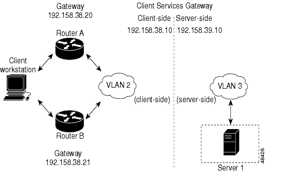
In the single subnet (bridge) mode configuration, the client-side and server-side VLANs are on the same subnets. Figure 4-1 shows how the single subnet (bridge) mode configuration is set up.
Figure 4-1 Single Subnet (Bridge) Mode Configuration
Note
Note
To configure content switching for the single subnet (bridge) mode, perform this task:
Step 1
Router(config-module-csm)# vlan
database
Enters the VLAN mode1 .
Step 2
Router(vlan)# vlan 2Configures a client-side VLAN2 .
Step 3
Router(vlan)# vlan 3Configures a server-side VLAN.
Step 4
Router(vlan)# exitExits to have the configuration take effect.
Step 5
Router(config-module-csm)# vlan 2
client
Creates the client-side VLAN 2 and enters the SLB VLAN mode 1.
Step 6
Router(config-slb-vlan-client)# ip
addr 192.158.38.10 255.255.255.0
Assigns the CSM IP address on VLAN 2.
Step 7
Router(config-slb-vlan-client)#
gateway 192.158.38.20
Defines the client-side VLAN gateway to Router A.
Step 8
Router(config-slb-vlan-client)#
gateway 192.158.38.21
Defines the client-side VLAN gateway to Router B.
Step 9
Router(config-slb-vserver)# vlan 3
server
Creates the server-side VLAN 3 and enters the SLB VLAN mode.
Step 10
Router(config-slb-vlan-client)# ip
addr 192.158.38.10 255.255.255.0
Assigns the CSM IP address on VLAN 3.
Step 11
Router(config-slb-vlan-client)# exitExits the submode.
Step 12
Router(config-module-csm)# vserver
VIP1
Creates a virtual server and enters the SLB vserver mode.
Step 13
Router(config-slb-vserver)# virtual
192.158.38.30 tcp www
Creates a virtual IP address.
Step 14
Router(config-slb-vserver)# serverfarm
farm1
Associates the virtual server with the server farm3 .
Step 15
Router(config-module-csm)# inserviceEnables the server.
1 Enter the exit command to leave a mode or submode. Enter the end command to return to the menu's top level.
2 The no form of this command restores the defaults.
3 This step assumes that the server farm has already been configured. See the "Configuring Server Farms" section on page 3-12.
Note
Configuring the Secure (Router) Mode
In secure (router) mode, the client-side and server-side VLANs are on different subnets. Figure 4-2 shows how the secure (router) mode configuration is set up.
Figure 4-2 Secure (Router) Mode Configuration
Note
To configure content switching in secure (router) mode, perform this task:
Step 1
Router(config-module-csm)# vlan databaseEnters the VLAN mode1 .
Step 2
Router(vlan)# vlan 2Configures a client-side VLAN2 .
Step 3
Router(vlan)# vlan 3Configures a server-side VLAN.
Step 4
Router(vlan)# exitExits to have the configuration take effect.
Step 5
Router(config-module-csm)# vlan 2 clientCreates the client-side VLAN 2 and enters the SLB VLAN mode.
Step 6
Router(config-slb-vlan-client)# ip addr
192.158.38.10 255.255.255.0
Assigns the CSM IP address on VLAN 2.
Step 7
Router(config-slb-vlan-client)# gateway
192.158.38.20
Defines the client-side VLAN gateway to Router A.
Step 8
Router(config-slb-vlan-client)# gateway
192.158.38.21
Defines the client-side VLAN gateway to Router B.
Step 9
Router(config-module-csm)# vlan 3 serverCreates the server-side VLAN 3 and enters the SLB VLAN mode.
Step 10
Router(config-slb-vlan-server)# ip addr
192.158.39.10 255.255.255.0
Assigns the CSM IP address on VLAN 3.
Step 11
Router(config-slb-vlan-server)# exitExits the submode.
Step 12
Router(config-module-csm)# vserver VIP1Creates a virtual server and enters the SLB vserver mode.
Step 13
Router(config-slb-vserver)# virtual
192.158.38.30 tcp www
Creates a virtual IP address.
Step 14
Router(config-slb-vserver)# serverfarm
farm1
Associates the virtual server with the server farm3 .
Step 15
Router(config-module-csm)# inserviceEnables the server.
1 Enter the exit command to leave a mode or submode. Enter the end command to return to the menu's top level.
2 The no form of this command restores the defaults.
3 This step assumes that the server farm has already been configured. See the "Configuring Server Farms" section on page 3-12.
Note
Configuring Fault Tolerance
This section describes a fault-tolerant configuration. In this configuration, two separate Catalyst 6000 family chassis each contain a CSM.
Note
In the secure (router) mode, the client-side and server-side VLANs provide the fault-tolerant (redundant) connection paths between the CSM and the routers on the client side and the servers on the server side. In a redundant configuration, two CSMs perform active and standby roles. Each CSM contains the same IP, virtual server, server pool, and real server information. From the client-side and server-side networks, each CSM is configured identically. The network sees the fault-tolerant configuration as a single CSM.
Note
Configuring fault-tolerance requires the following:
•
•
•
•
•
•
The following command enables the calendar:
Cat6k-2# conf tCat6k-2(config)# clock timezone WORD offset from UTCCat6k-2(config)# clock calendar-validQuality of service (QoS) configured on each CSM in the fault-tolerant pair with Cisco IOS Release 12.1(8)E and later.
Table 4-1 lists the QoS requirements.
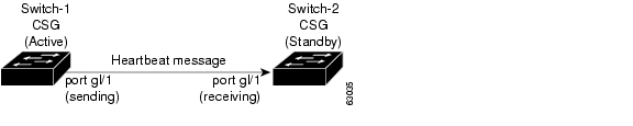
Figure 4-3 shows the QoS configuration topology.
Figure 4-3 QoS Configuration Topology
Without this configuration, 802.1Q priority information is not preserved in packets traversing through to the switch. Heartbeat messages sent from the active to the standby CSM must contain this priority information so that they will be transmitted without delay. When an excessive delay occurs, an unnecessary takeover might occur.
You can overcome this limitation by configuring the sending port g1/1 to retain priority information upon transmission and the receiving port g1/1 to trust the class of service (CoS) (priority bits) for the incoming packets.
The permit any any command informs the switch to accept incoming packets with any MAC address from any MAC address.
To configure QoS for a fault-tolerant configuration, enter these commands:
Cat6k-2(config)# mls qosCat6k-2(config)# interface g1/1Cat6k-2(config-if)# no shutdownCat6k-2(config-if)# mls qos cos 7Cat6k-2(config-if)# switchportCat6k-2(config-if)# switchport access vlan 200Cat6k-2(config-if)# switchport trunk encapsulation dot1qCat6k-2(config-if)# switchport trunk allowed vlan 1,2,1002-1005Cat6k-2(config-if)# switchport mode trunkTable 4-2 lists CSM fault-tolerant configuration requirements.
Table 4-2 CSM Fault-tolerant Configuration Requirements
VLAN name
X
VLAN address
X
Gateway1 address
X
Virtual server name
X
Virtual IP address
X
Alias IP addresses
X
Redundancy group name
X
Redundancy VLAN ID
X
1 Server default gateways must point to the alias IP address.
Because each CSM has a different IP address on the client-side and server-side VLAN, the CSM can issue health monitor probes (see the "Configuring Probes for Health Monitoring" section on page 6-1) to the network and receive responses. Both the active and standby CSMs send probes while operational. If the passive CSM assumes control, it knows the status of the servers because of the probe responses it has received.
Enter the replicate csrp {sticky | connection} command in the virtual server mode to configure replication for the CSMs.
Note
If no router is present on the server-side VLAN, then each server's default route points to the aliased IP address.
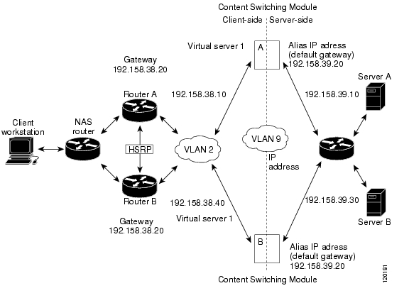
Figure 4-4 shows how the secure (router) mode fault-tolerant configuration is set up.
Figure 4-4 Fault-Tolerant Configuration
Note
To configure the active (A) CSM for fault tolerance, perform this task:
Step 1
Router(config-module-csm)# vlan 2 clientCreates the client-side VLAN 2 and enters the SLB VLAN mode1 .
Step 2
Router(config-slb-vlan-client)# ip addr
192.158.38.10 255.255.255.0
Assigns the content switching IP address on VLAN 2.
Step 3
Router(config-slb-vlan-client)# gateway
192.158.38.20 255.255.255.0
(Optional) Defines the client-side VLAN gateway for an HSRP enabled gateway.
Step 4
Router(config-module-csm)# vserver vip1Creates a virtual server and enters the SLB vserver mode.
Step 5
Router(config-slb-vserver)# virtual
192.158.38.30 tcp www
Creates a virtual IP address.
Step 6
Router(config-slb-vserver)# inserviceEnables the server.
Step 7
Router(config-module-csm)# vlan 3 serverCreates the server-side VLAN 3 and enters the SLB VLAN mode.
Step 8
Router(config-slb-vlan-server)# ip addr
192.158.39.10 255.255.255.0
Assigns the CSM IP address on VLAN 3.
Step 9
Router(config-slb-vlan-server)# alias ip
addr 192.158.39.20 255.255.255.0
Assigns the default route for VLAN 3.
Step 10
Router(config-module-csm) vlan 9 ftDefines VLAN 9 as a fault-tolerant VLAN.
Step 11
Router(config-module-csm)# ft group
ft-group-number vlan 9
Creates the content switching active and standby (A/B) group VLAN 9.
Step 12
Router(config-module-csm)# vlan databaseEnters the VLAN mode 1.
Step 13
Router(vlan)# vlan 2Configures a client-side VLAN 22 .
Step 14
Router(vlan)# vlan 3Configures a server-side VLAN 3.
Step 15
Router(vlan)# vlan 9Configures a fault-tolerant VLAN 9.
Step 16
Router(vlan)# exitEnters the exit command to have the configuration take affect.
1 Enter the exit command to leave a mode or submode. Enter the end command to return to the menu's top level.
2 The no form of this command restores the defaults.
To configure the standby (B) CSM for fault tolerance, perform this task (see Figure 4-4):
Step 1
Router(config-module-csm)# vlan 2 clientCreates the client-side VLAN 2 and enters the SLB VLAN mode1 .
Step 2
Router(config-slb-vlan-client)# ip addr
192.158.38.40 255.255.255.0
Assigns the Content Switching IP address on VLAN 2.
Step 3
Router(config-module-csm) vlan 9 ftDefines VLAN 9 as a fault-tolerant VLAN.
Step 4
Router(config-slb-vlan-client)# gateway
192.158.38.20
Defines the client-side VLAN gateway.
Step 5
Router(config-module-csm)# vserver vip1Creates a virtual server and enters the SLB vserver mode.
Step 6
Router(config-slb-vserver)# virtual
192.158.38.30 tcp www
Creates a virtual IP address.
Step 7
Router(config-slb-vserver)# inserviceEnables the server.
Step 8
Router(config-module-csm)# vlan 3 serverCreates the server-side VLAN 3 and enters the SLB vlan mode.
Step 9
Router(config-slb-vlan-server)# ip addr
192.158.39.30 255.255.255.0
Assigns the CSM IP address on VLAN 3.
Step 10
Router(config-slb-vlan-server)# alias
192.158.39.20 255.255.255.0
Assigns the default route for VLAN 2.
Step 11
Router(config-module-csm)# ft group
ft-group-number vlan 9
Creates the CSM active and standby (A/B) group VLAN 9.
Step 12
Router(config-module-csm)# show module csm ftDisplays the state of the fault tolerant system.
1 Enter the exit command to leave a mode or submode. Enter the end command to return to the menu's top level.
Configuring HSRP
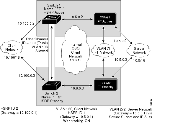
This section provides an overview of a Hot Standby Router Protocol (HSRP) configuration (see Figure 4-5) and describes how to configure the CSMs with HSRP and CSM failover on the Catalyst 6000 family switches.
HSRP Configuration Overview
Figure 4-5 shows that two Catalyst 6000 family switches, Switch 1 and Switch 2, are configured to route from a client-side network (10.100/16) to an internal CSM client network (10.6/16, VLAN 136) through an HSRP gateway (10.100.0.1). The configuration shows the following:
•
•
Note
In the example configuration, two CSMs (one in Switch 1 and one in Switch 2) are configured to forward traffic between a client-side and a server-side VLAN:
•
Note
•
The actual servers on the server network (10.5/1) point to the CSM server network through an aliased gateway (10.5.0.1), allowing the servers to run a secure subnet.
In the example configuration, an EtherChannel is set up with trunking enabled, allowing traffic on the internal CSM client network to travel between the two Catalyst 6000 family switches. The setup is shown in Figure 4-5.
Note
Figure 4-5 HSRP Configuration
Creating the HSRP Gateway
This procedure describes how to create an HSRP gateway for the client-side network. The gateway is HSRP ID 2 for the client-side network.
Note
To create an HSRP gateway, follow these steps:
Step 1
Router(config)#interface FastEthernet3/6Router(config)#ip address 10.100.0.2 255.255.0.0Router(config)#standby 2 priority 110 preemptRouter(config)#standby 2 ip 10.100.0.1Step 2
Router(config)#interface FastEthernet3/6Router(config)#ip address 10.100.0.3 255.255.0.0Router(config)#standby 2 priority 100 preemptRouter(config)#standby 2 ip 10.100.0.1Creating Fault-Tolerant HSRP Configurations
This section describes how to create a fault-tolerant HSRP secure-mode configuration. To create a nonsecure-mode configuration, enter the commands described with these exceptions:
•
•
To create fault-tolerant HSRP configurations, follow these steps:
Step 1
Router(config)# module csm 5Router(config-module-csm)# vlan 136 clientRouter(config-slb-vlan-client)# ip address 10.6.0.245 255.255.0.0Router(config-slb-vlan-client)# gateway 10.6.0.1Router(config-slb-vlan-client)# exitRouter(config-module-csm)# vlan 272 serverRouter(config-slb-vlan-server)# ip address 10.5.0.2 255.255.0.0Router(config-slb-vlan-server)# alias 10.5.0.1 255.255.0.0Router(config-slb-vlan-server)# exitRouter(config-module-csm)# vlan 71 ftRouter(config-module-csm)# ft group 88 vlan 71Router(config-slb-ft)# priority 30Router(config-slb-ft)# preemptRouter(config-slb-ft)# exitRouter(config-module-csm)# interface Vlan136ip address 10.6.0.2 255.255.0.0standby 1 priority 100 preemptstandby 1 ip 10.6.0.1standby 1 track Fa3/6 10Step 2
Router(config)# module csm 6Router(config-module-csm)# vlan 136 clientRouter(config-slb-vlan-client)# ip address 10.6.0.246 255.255.0.0Router(config-slb-vlan-client)# gateway 10.6.0.1Router(config-slb-vlan-client)# exitRouter(config-module-csm)# vlan 272 serverRouter(config-slb-vlan-server)# ip address 10.5.0.3 255.255.0.0Router(config-slb-vlan-server)# alias 10.5.0.1 255.255.0.0Router(config-slb-vlan-server)# exitRouter(config-module-csm)# vlan 71 ftRouter(config-module-csm)# ft group 88 vlan 71Router(config-slb-ft)# priority 20Router(config-slb-ft)# preemptRouter(config-slb-ft)# exitRouter(config-module-csm)# interface Vlan136ip address 10.6.0.3 255.255.0.0standby 1 priority 100 preemptstandby 1 ip 10.6.0.1standby 1 track Fa3/6 10
Note
Step 3
Router(console)# interface Port-channel100Router(console)# switchportRouter(console)# switchport trunk encapsulation dot1qRouter(console)# switchport trunk allowed vlan 136
Note
To prevent problems, remove the server and FT CSM VLANs as follows:Router(console)# switchport trunk remove vlan 71Router(console)# switchport trunk remove vlan 272Step 4
Router(console)# interface FastEthernet3/25Router(console)# switchportRouter(console)# channel-group 100 mode on
![]()
![]()
![]()
![]()
![]()
![]()
![]()
![]()
Posted: Wed Jun 29 11:05:02 PDT 2005
All contents are Copyright © 1992--2005 Cisco Systems, Inc. All rights reserved.
Important Notices and Privacy Statement.