|
|

Table Of Contents
Configuring Advanced Server Load Balancing
Configuring a URL Hashing Predictor
Configuring Beginning and Ending Patterns
Configuring Firewall Load Balancing
Understanding How Firewalls Work
Configuring Stealth Firewall Load Balancing
Configuring Regular Firewall Load Balancing
Configuring Generic Header Parsing
Configuring Generic Header Parsing
Configuring Persistent Connections
Configuring Connection Redundancy
Configuring SNMP Traps for Real Servers
Configuring Advanced Server Load Balancing
This chapter describes how to configure advanced server load balancing (SLB) on the CSM and contains these sections:
•
Configuring Firewall Load Balancing
•
•
•
•
•
Configuring URL Hashing
When you choose a server farm for a connection, you can select a specific real server in that server farm. You can choose least connections, round robin, or URL hashing to select a real server.
URL hashing is a load-balancing predictor for Layer 7 connections. You can configure URL hashing on the CSM on a server farm-by-server farm basis. The CSM chooses the real server by using a hash value based on a URL. This hash value may be computed on the entire URL or on a portion of it. To select only a portion of the URL for hashing, you can specify the beginning and ending patterns in the URL so that only the portion of the URL from the specified beginning pattern through the specified ending pattern is hashed.
The CSM supports URL hashing in software release 2.1(1).
Configuring a URL Hashing Predictor
You configure the URL hashing predictor on a server farm-by-server farm basis. Unless you specify a beginning and an ending pattern (see the "Configuring Beginning and Ending Patterns" section), the entire URL is hashed and used to select a real server.
You must configure URL hashing for all server farms that will be using the URL hashing predictor, regardless of whether they are using the entire URL or a beginning and ending pattern.
To configure URL hashing as a load-balancing predictor for a server farm, perform this task:
Router(config-slb-sfarm)#
predictor hash url
Configures the URL hashing and load-balancing predictor for a server farm.
This example shows how to configure URL hashing and load-balancing predictor for a server farm:
Router(config)# mod csm 2Router(config-module-csm)# serverfarm farm1Router(config-slb-sfarm)# predictor hash urlRouter(config-slb-sfarm)# real 10.1.0.105Router(config-slb-real)# inserviceRouter(config-slb-real)# exitConfiguring Beginning and Ending Patterns
When you configure a beginning and ending pattern, you do so at the virtual server level. The pattern you define will apply to all the server farms assigned to all of the policies in that virtual server that have URL hashing enabled.
The beginning and ending pattern delimits the portion of the URL that will be hashed and used as a predictor to select a real server from a server farm that belongs to any policy assigned to that virtual server.
To hash a substring of the URL instead of the entire URL, specify the beginning and ending patterns in vserver vserver-name submode with the url-hash begin-pattern pattern-a command and url-hash end-pattern pattern-b command. Hashing occurs at the start of the beginning pattern and goes to the ending pattern.
For example, in the following URL, if the beginning pattern is c&k=, and the ending pattern is &, only the substring c&k=c is hashed:
http://quote.yahoo.com/q?s=csco&d=c&k=c1&t=2y&a=v&p=s&l=on&z=m&q=l\
Note
This example shows how to configure beginning and ending patterns for URL hashing:
Router(config-module-csm)#Router(config-module-csm)# vserver vs1Router(config-slb-vserver)# virtual 10.1.0.81 tcp 80Router(config-slb-vserver)# url-hash begin-pattern c&k= end-pattern &Router(config-slb-vserver)# serverfarm farm1Router(config-slb-vserver)# inserviceRouter(config-slb-vserver)#Router(config-slb-vserver)# exitRouter(config-module-csm)# exitConfiguring Firewall Load Balancing
Firewall load balancing allows you to scale firewall protection by distributing traffic across multiple firewalls on a per-connection basis. All packets belonging to a particular connection must go through the same firewall. The firewall then allows or denies transmission of individual packets across its interfaces.
This section describes how to configure firewall load balancing for regular and stealth firewalls. It covers the following topics:
•
•
•
•
Understanding How Firewalls Work
A firewall forms a physical barrier between two parts of a network, the Internet and an intranet, for example. When a firewall accepts a packet from one side (the Internet), it sends the packet through to the other side (the intranet). A firewall can modify a packet before passing it through or send it through unaltered. When a firewall rejects a packet, it usually drops the packet and logs the dropped packet as an event.
After a session is established and a flow of packets begins, a firewall can monitor each packet in the flow or allow the flow to continue, unmonitored, depending on the policies that are configured on that firewall.
Firewalls Types
The two basic types of firewalls are as follows:
•
•
Regular firewalls have a presence on the network; they are assigned an IP address that allows them to be addressed as a device and seen by other devices on the network.
Stealth firewalls have no presence on the network; they are not assigned an IP address and cannot be addressed or seen by other devices on the network. To the network, a stealth firewall is part of the wire.
Both firewall types examine traffic moving in both directions (between the protected and the unprotected side of the network) and accept or reject packets based on user-defined sets of policies.
How the CSM Distributes Traffic to Firewalls
The CSM load-balances traffic to devices configured in server farms. These devices can be servers, firewalls, or any IP-addressable object including an alias IP address. The CSM uses load-balancing algorithms to determine how the traffic is balanced among the devices configured in server farms, independent of device type.
Note
Supported Firewalls
The CSM can load-balance traffic to regular or stealth firewalls.
For regular firewalls, a single CSM or a pair of CSMs balances traffic among firewalls that contain unique IP addresses, similar to how it balances traffic to servers.
For stealth firewalls, a CSM balances traffic among unique VLAN alias IP address interfaces on another CSM that provide paths through stealth firewalls. A stealth firewall is configured so that all traffic moving in both directions across that VLAN moves through the firewall.
Layer 3 Load Balancing to Firewalls
When the CSM load-balances traffic to firewalls, the CSM performs the same function that it performs when it load-balances to servers. To configure Layer 3 load balancing to firewalls, follow these steps:
Step 1
Step 2
Step 3
Note
Types of Firewall Configurations
The CSM supports these two firewall configuration types:
•
•
CSM Firewall Configurations
The CSM can support these firewall configurations:
•
•
•
•
In Figure 5-1, traffic moves through the firewalls and is filtered in both directions. The figure shows the flow from the Internet to the intranet. On the path to the intranet, CSM A balances traffic across VLANs 5, 6, and 7 through firewalls to CSM B. On the path to the Internet, CSM B balances traffic across VLANs 15, 16, and 17 through firewalls to CSM A. CSM A uses the VLAN aliases of CSM B in its server farm, and CSM B uses the VLAN aliases of CSM A in its server farm.
Figure 5-1 Stealth Firewall Configuration (Dual CSMs Only)
In Figure 5-2, traffic moves through the firewalls and is filtered in both directions. The figure shows the flow from the Internet to the intranet. VLANs 11 and 111 are on the same subnet, and VLANs 12 and 112 are on the same subnet.
Figure 5-2 Regular Firewall Configuration (Dual CSMs)
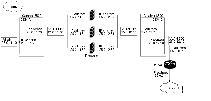
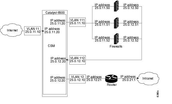
In Figure 5-3, traffic moves through the firewalls and is filtered in both directions. The figure only shows the flow from the Internet to the intranet, and VLANs 11 and 111 are on the same subnet.
VLANs 12 and 112 are on the same subnet.Figure 5-3 Regular Firewall Configuration (Single CSM)
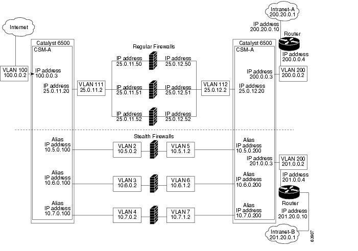
In Figure 5-4, traffic moves through both the regular and stealth firewalls and is filtered in both directions. The figure shows the flow from the Internet to the intranet. VLANs 5, 6, and 7 are shared between CSM A and CSM B. On the path to the intranet, CSM A balances traffic across VLANs 5, 6, and 7 through firewalls to CSM B. On the path to the intranet, CSM B balances traffic across VLANs 5, 6, and 7 through firewalls to CSM A.
Figure 5-4 Mixed Firewall Configuration for Stealth and Regular Firewalls (Dual CSMs Only)
Fault-Tolerant CSM Firewall Configurations
The CSM supports fault tolerance for these configurations:
•
•
•
•
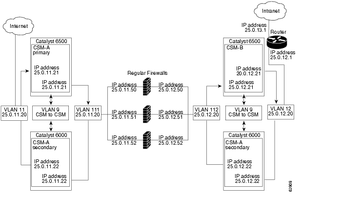
In Figure 5-5, the traffic moves through the firewalls and is filtered in both directions. The figure only shows the flow from the Internet to the intranet through the primary CSMs, and VLANs 11 and 111 are on the same subnet. VLANs 12 and 112 are on the same subnet.
Figure 5-5 Fault-Tolerant, Regular Firewall Configuration-(Dual CSMs)
Configuring Stealth Firewall Load Balancing
This section describes how to configure firewall load balancing for stealth firewalls and covers the following information:
•
•
Stealth Firewall Configuration
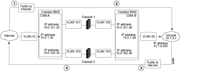
In a stealth firewall configuration, firewalls connect to two different VLANs and are configured with IP addresses on the VLANs to which they connect. (See Figure 5-6.)
Figure 5-6 Stealth Firewall Configuration Example
Figure 5-6 shows two regular firewalls (Firewall 1 and Firewall 2) sandwiched between two CSMs
(CSM A and CSM B).
Note
On the path from the Internet to the intranet, traffic enters the insecure side of the firewalls through separate VLANs, VLAN 101 and VLAN 103, and exits the secure side of the firewalls through separate VLANs, VLAN 102 and VLAN 104. On the path from the intranet to the Internet, the flow is reversed. VLANs also provide connectivity to the Internet (VLAN 10) and to the intranet (VLAN 20).
In a stealth configuration, CSM A and CSM B load balance traffic through the firewalls.
Stealth Firewall Configuration Example
The stealth firewall configuration example contains two CSMs (CSM A and CSM B) installed in separate Catalyst 6000 family switches.
Note
This section describes how to create the stealth firewall configuration for CSM A and CSM B.
Configuring CSM A (Stealth Firewall Example)
To create the regular configuration example, perform these tasks for CSM A:
•
•
Note
Creating VLANs on Switch A
To create two VLANs on switch A, perform this task:
Step 1
Switch-A(config)# vlan databaseEnters the VLAN mode.1
Step 2
Switch-A(vlan)# vlan 10Creates VLAN 102 .
Step 3
Switch-A(vlan)# vlan 101Creates VLAN 1013 .
Step 4
Switch-A(vlan)# vlan 103Creates VLAN 1034 .
1 Do this step on the switch console of the switch that contains CSM A.
2 VLAN 10 connects CSM A to the Internet.
3 VLAN 101 provides a connection through Firewall 1 to CSM B.
4 VLAN 103 provides a connection through Firewall 2 to CSM B
Configuring VLANs on CSM A
To configure the three VLANs, perform this task:
Step 1
Switch-A(config)# module csm 5Enters multiple module configuration mode and specifies that CSM A is installed in slot 5.
Step 2
Switch-A(config-module-csm)# vlan 10
client
Specifies VLAN 10 as the VLAN that is being configured, identifies it as a client VLAN, and enters VLAN configuration mode.
Step 3
Switch-A(config-slb-vlan-client)# ip
address 10.0.1.35 255.255.255.0
Specifies an IP address and netmask for VLAN 10.
Step 4
Switch-A(config-slb-vlan-client)# alias
10.0.1.30 255.255.255.0
Specifies an alias IP address and netmask for VLAN 101 .
Step 5
Switch-A(config-slb-vlan-client)# exitReturns to VLAN configuration mode.
Step 6
Switch-A(config-module-csm)# vlan 101
server
Specifies VLAN 101 as the VLAN that is being configured, identifies it as a server VLAN, and enters VLAN configuration mode.
Step 7
Switch-A(config-slb-vlan-server)# ip
address 10.0.101.35 255.255.255.0
Specifies an IP address and netmask for VLAN 101.
Step 8
Switch-A(config-slb-vlan-server)# alias
10.0.101.100 255.255.255.0
Specifies an alias IP address and netmask for VLAN 101 1.
Step 9
Switch-A(config-slb-vlan-server)# exitReturns to VLAN configuration mode.
Step 10
Switch-A(config-module-csm)# vlan 103
server
Specifies VLAN 103 as the VLAN that is being configured, identifies it as a server VLAN, and enters VLAN configuration mode.
Step 11
Switch-A(config-slb-vlan)# ip address
10.0.102.35 255.255.255.0
Specifies an IP address and netmask for VLAN 103.
Step 12
Switch-A(config-slb-vlan)# alias
10.0.102.100 255.255.255.0
Specifies an alias IP address and netmask for VLAN 103 1.
1 This step provides a target for CSM B to use in making a load-balancing decision.
Configuring Server Farms on CSM A
Note
To configure two server farms on CSM A, perform this task:
Step 1
Switch-A(config)# module csm 5Enters multiple module configuration mode and specifies that CSM A is installed in slot 5.
Step 2
Switch-A(config-module-csm)# serverfarm
FORWARD-SF
Creates and names the FORWARD-SF1 server farm (actually a forwarding policy) and enters server farm configuration mode.
Step 3
Switch-A(config-slb-sfarm)# no nat serverDisables the NAT of server IP addresses and port numbers2 .
Step 4
Switch-A(config-slb-sfarm)# predictor
forward
Forwards traffic in accordance with its internal routing tables rather than a load-balancing algorithm.
Step 5
Switch-A(config-slb-sfarm)# exitReturns to multiple module configuration mode.
Step 6
Switch-A(config-module-csm)# serverfarm
TO-INSIDE-SF
Creates and names the INSIDE-SF3 server farm (that will contain alias IP addresses rather than real servers) and enters server farm configuration mode.
Step 7
Switch-A(config-slb-sfarm)# no nat serverDisables the NAT of server IP address and port number4 .
Step 8
Switch-A(config-slb-sfarm)# predictor
hash address source 255.255.255.255
Selects a server using a hash value based on the source IP address5 .
Step 9
Switch-A(config-slb-sfarm)# real
10.0.101.200
Identifies the alias IP address of CSM B that lies on the path to Firewall 1 as a real server and enters real server configuration submode.
Step 10
Switch-A(config-slb-real)# inserviceEnables the firewall.
Step 11
Switch-A(config-slb-real)# exitReturns to server farm configuration mode.
Step 12
Switch-A(config-slb-sfarm)# real
10.0.102.200
Identifies the alias IP address of CSM B that lies on the path to Firewall 2 as a real server and enters real server configuration submode.
Step 13
Switch-A(config-slb-real)# inserviceEnables the firewall.
1 FORWARD-SF is actually a route forwarding policy, not an actual server farm, that allows traffic to reach the Internet (through VLAN 10). It does not contain any real servers.
2 This step is required when configuring a server farm that contains a forwarding policy rather than real servers.
3 INSIDE-SF contains the two alias IP addresses of CSM B listed as real servers that allow traffic from the intranet to reach CSM B.
4 This step is required when configuring a server farm that contains firewalls.
5 We recommend this step when configuring insecure-side firewall interfaces in a server farm.
Configuring Virtual Servers on CSM A
To configure three virtual servers on CSM A, perform this task:
Step 1
Switch-A(config)# module csm 5Enters multiple module configuration mode and specifies that the CSM A is installed in slot 5.
Step 2
Switch-A(config-module-csm)# vserver
FORWARD-V101
Specifies FORWARD-V1011 as the virtual server that is being configured and enters virtual server configuration mode.
Step 3
Switch-A(config-slb-vserver)# virtual
0.0.0.0 0.0.0.0 any
Specifies a match for any IP address and any protocol2 .
Step 4
Switch-A(config-slb-vserver))# vlan 101Specifies that the virtual server will only accept traffic arriving on VLAN 101, which is traffic arriving from the insecure side of the firewalls.
Step 5
Switch-A(config-slb-vserver)# serverfarm
FORWARD-SF
Specifies the server farm for this virtual server3 .
Step 6
Switch-A(config-slb-vserver)# inserviceEnables the virtual server.
Step 7
Switch-A(config-slb-vserver)# exitReturns to multiple module configuration mode.
Step 8
Switch-A(config-module-csm)# vserver
FORWARD-V103
Specifies FORWARD-V1034 as the virtual server that is being configured and enters virtual server configuration mode.
Step 9
Switch-A(config-slb-vserver)# virtual
0.0.0.0 0.0.0.0 any
Specifies a match for any IP address and any protocol5 .
Step 10
Switch-A(config-slb-vserver))# vlan 103Specifies that the virtual server will only accept traffic arriving on VLAN 103, which is traffic arriving from the insecure side of the firewalls.
Step 11
Switch-A(config-slb-vserver)# serverfarm
FORWARD-SF
Specifies the server farm for this virtual server 3.
Step 12
Switch-A(config-slb-vserver)# inserviceEnables the virtual server.
Step 13
Switch-A(config-slb-vserver)# exitReturns to multiple module configuration mode.
Step 14
Switch-A(config-module-csm)# vserver
OUTSIDE-VS
Specifies OUTSIDE-VS6 as the virtual server that is being configured and enters virtual server configuration mode.
Step 15
Switch-A(config-slb-vserver)# virtual
10.1.0.0 255.255.255.0 any
Specifies the IP address, netmask, and protocol (any) for this virtual server. Clients reach the server farm represented by this virtual server through this address.
Step 16
Switch-A(config-slb-vserver))# vlan 10Specifies that the virtual server will only accept traffic arriving on VLAN 10, which is traffic arriving from the Internet.
Step 17
Switch-A(config-slb-vserver)# serverfarm
TO-INSIDE-SF
Specifies the server farm for this virtual server7 .
Step 18
Switch-A(config-slb-vserver)# inserviceEnables the virtual server.
1 FORWARD-V101 allows Internet traffic to reach the insecure side of the firewalls (through VLAN 101).
2 Client matching is only limited by VLAN restrictions (see Step 4).
3 This server farm is actually a forwarding predictor rather than an actual server farm containing real servers.
4 FORWARD-V103 allows Internet traffic to reach the insecure side of the firewalls (through VLAN 103).
5 Clients will always match-only being limited by VLAN restrictions. (See Step 10.)
6 OUTSIDE-VS allows traffic from the Internet to reach CSM A (through VLAN 10).
7 The server farm contains the alias IP addresses of CSM B that lie along the path of Firewall 1 and Firewall 2.
Configuring CSM B (Stealth Firewall Example)
To create the regular configuration example, perform the following configuration tasks for CSM B:
•
•
Note
Creating VLANs on Switch B
To create three VLANs on Switch B, perform this task:
Note
Step 1
Switch-B(config)# vlan databaseEnters the VLAN mode1 .
Step 2
Switch-B(vlan)# vlan 102Creates VLAN 1022 .
Step 3
Switch-B(vlan)# vlan 104Creates VLAN 1043 .
Step 4
Switch-B(vlan)# vlan 200Creates VLAN 2004 .
1 Do this step on the switch console of the switch that contains CSM B.
2 VLAN 102 provides a connection through Firewall 1 to CSM A.
3 VLAN 104 provides a connection through Firewall 2 to CSM A.
4 VLAN 200 provides the connection to the internal network.
Configuring VLANs on CSM B
To configure the three VLANs, perform this task:
Step 1
Switch-B(config)# module csm 6Enters multiple module configuration mode and specifies that CSM B is installed in slot 6.
Step 2
Switch-B(config-module-csm)# vlan 102
server
Specifies VLAN 102 as the VLAN that is being configured, identifies it as a server VLAN, and enters VLAN configuration mode.
Step 3
Switch-B(config-slb-vlan-server)# ip
address 10.0.101.36 255.255.255.0
Specifies an IP address and netmask for VLAN 102.
Step 4
Switch-B(config-slb-vlan-server)# alias
10.0.101.200 255.255.255.0
Specifies an alias IP address and netmask for VLAN 1021 .
Step 5
Switch-B(config-slb-vlan-server)# exitReturns to multiple module configuration mode.
Step 6
Switch-B(config-module-csm)# vlan 104
server
Specifies VLAN 104 as the VLAN that is being configured, identifies it as a server VLAN, and enters VLAN configuration mode.
Step 7
Switch-B(config-slb-vlan-server)# ip
address 10.0.102.36 255.255.255.0
Specifies an IP address and netmask for VLAN 104.
Step 8
Switch-B(config-slb-vlan)# alias
10.0.102.200 255.255.255.0
Specifies an alias IP address and netmask for VLAN 104 1.
Step 9
Switch-B(config-slb-vlan-server)# exitReturns to multiple module configuration mode.
Step 10
Switch-B(config-module-csm)# vlan 20
server
Specifies VLAN 20 as the VLAN that is being configured, identifies it as a server VLAN, and enters VLAN configuration mode.
Step 11
Switch-B(config-slb-vlan-server)# ip
address 10.1.0.36 255.255.255.0
Specifies an IP address and netmask for VLAN 20.
1 This step provides a target for CSM A to use in making a load-balancing decision.
Configuring Server Farms on CSM B
To configure three server farms on CSM B, perform this task:
Note
Step 1
Switch-B(config)# module csm 6Enters multiple module configuration mode and specifies that CSM B is installed in slot 6.
Step 2
Switch-B(config-module-csm)# serverfarm
FORWARD-SF
Creates and names the FORWARD-SF1 server farm (actually a forwarding policy) and enters server farm configuration mode.
Step 3
Switch-B(config-slb-sfarm)# no nat serverDisables the NAT of server IP addresses and port numbers2 .
Step 4
Switch-B(config-slb-sfarm)# predictor
forward
Forwards traffic in accordance with its internal routing tables rather than a load-balancing algorithm.
Step 5
Switch-B(config-slb-sfarm)# exitReturns to multiple module configuration mode.
Step 6
Switch-B(config-module-csm)# serverfarm
TO-OUTSIDE-SF
Creates and names the GENERIC-SF server farm and enters server farm configuration mode3 .
Step 7
Switch-B(config-slb-sfarm)# no nat serverDisables NAT of server IP addresses and port numbers4 .
Step 8
Switch-B(config-slb-sfarm)# real
10.0.101.100
Identifies the alias IP address of CSM A that lies on the path to Firewall 1 as a real server and enters real server configuration submode.
Step 9
Switch-B(config-slb-real)# inserviceEnables the real (actually an alias IP address).
Step 10
Switch-B(config-slb-real)# exitReturns to server farm configuration mode.
Step 11
Switch-B(config-slb-sfarm)# real
10.0.102.100
Identifies the alias IP address of CSM B that lies on the path to Firewall 2 as a real server and enters real server configuration submode.
Step 12
Switch-B(config-slb-real)# inserviceEnables the real server (actually an alias IP address).
Step 13
Switch-B(config-slb-real)# exitReturns to server farm configuration mode.
Step 14
Switch-B(config-module-csm)# serverfarm
SERVERS-SF
Creates and names the SERVERS-SF5 server farm and enters serverfarm configuration mode.
Step 15
Switch-B(config-slb-sfarm)# real
10.1.0.101
Identifies a server in the intranet as a real server, assigns it an IP address, and enters real server configuration submode.
Step 16
Switch-B(config-slb-real)# inserviceEnables the real server.
Step 17
Switch-B(config-slb-real)# exitReturns to server farm configuration mode.
Step 18
Switch-B(config-slb-sfarm)# real
10.1.0.102
Identifies a server in the intranet as a real server, assigns it an IP address, and enters real server configuration submode.
Step 19
Switch-B(config-slb-real)# inserviceEnables the real server.
Step 20
Switch-B(config-slb-sfarm)# real
10.1.0.103
Identifies a server in the intranet as a real server, assigns it an IP address, and enters real server configuration submode.
Step 21
Switch-B(config-slb-real)# inserviceEnables the real server.
1 FORWARD-SF is actually a route forwarding policy, not an actual server farm, that allows traffic to reach the intranet (through VLAN 20). It does not contain any real servers.
2 This is a required step when configuring a server farm that contains a forwarding policy rather than real servers.
3 OUTSIDE-SF contains the two alias IP addresses of CSM A as the real servers allowing traffic from the intranet to reach CSM A.
4 This is a required step when configuring a server farm that contains a forwarding policy rather than real servers.
5 SERVERS-SF contains the IP addresses of the real servers located within the intranet.
Configuring Virtual Servers on CSM B
To configure three virtual servers on CSM, perform this task:
Step 1
Switch-B(config)# module csm 6Enters multiple module configuration mode and specifies that CSM B is installed in slot 6.
Step 2
Switch-B(config-module-csm)# vserver
FORWARD-VS-102
Specifies FORWARD-VS as the virtual server that is being configured and enters virtual server configuration mode.
Step 3
Switch-B(config-slb-vserver)# virtual
0.0.0.0 0.0.0.0 any
Specifies a match for any IP address and any protocol1 .
Step 4
Switch-B(config-slb-vserver)# vlan 102Specifies that the virtual server will only accept traffic arriving on VLAN 102, which is traffic arriving from the secure side of the Firewall 1.
Step 5
Switch-B(config-slb-vserver)# serverfarm
FORWARD-SF
Specifies the server farm for this virtual server2 .
Step 6
Switch-B(config-slb-vserver)# inserviceEnables the virtual server.
Step 7
Switch-B(config-slb-vserver)# exitReturns to multiple module configuration mode.
Step 8
Switch-B(config-module-csm)# vserver
FORWARD-VS-104
Specifies FORWARD-VS3 as the virtual server that is being configured and enters virtual server configuration mode.
Step 9
Switch-B(config-slb-vserver)# virtual
0.0.0.0 0.0.0.0 any
Specifies a match for any IP address and any protocol 1.
Step 10
Switch-B(config-slb-vserver)# vlan 104Specifies that the virtual server will only accept traffic arriving on VLAN 104, which is traffic arriving from the secure side of the Firewall 2.
Step 11
Switch-B(config-slb-vserver)# serverfarm
FORWARD-SF
Specifies the server farm for this virtual server 2.
Step 12
Switch-B(config-slb-vserver)# inserviceEnables the virtual server.
Step 13
Switch-B(config-slb-vserver)# exitReturns to multiple module configuration mode.
Step 14
Switch-B(config-module-csm)# vserver
INSIDE-VS
Specifies INSIDE-VS4 as the virtual server that is being configured and enters virtual server configuration mode.
Step 15
Switch-B(config-slb-vserver)# virtual
0.0.0.0 0.0.0.0 any
Specifies a match for any IP address and any protocol 1.
Step 16
Switch-B(config-slb-vserver)# vlan 20Specifies that the virtual server will only accept traffic arriving on VLAN 20, which is traffic arriving from the intranet.
Step 17
Switch-B(config-slb-vserver)# serverfarm
TO-OUTSIDE-SF
Specifies the server farm for this virtual server (containing the alias IP addresses of CSM A as real servers and allowing traffic to flow through Firewalls 1 and 2) and enters real server configuration submode.
Step 18
Switch-B(config-slb-vserver)# inserviceEnables the virtual server.
Step 19
Switch-B(config-slb-vserver)# exitReturns to multiple module configuration mode.
Step 20
Switch-B(config-module-csm)# vserver
TELNET-VS
Specifies TELNET-VS5 as the virtual server that is being configured and enters virtual server configuration mode.
Note
Step 21
Switch-B(config-slb-vserver)# virtual
10.1.0.200 255.255.255.0 tcp telnet
Specifies the IP address, netmask, protocol (TCP), and port (Telnet) for this virtual server6 .
Step 22
Switch-B(config-slb-vserver)# serverfarm
SERVERS-SF
Specifies the server farm containing real servers for this virtual server.
Step 23
Switch-B(config-slb-vserver)# inserviceEnables the virtual server.
1 Client matching is only limited by VLAN restrictions.
2 This server farm is actually a forwarding predictor rather than an actual server farm containing real servers.
3 FORWARD-VS allows traffic from the Internet to reach the intranet through VLAN 20.
4 INSIDE-VS allows traffic from the intranet to reach CSM A through Firewall 1 (through VLANs 102 and 101) or
Firewall 2 (through VLANs 104 and 103).5 TELNET-VS allows traffic from the Internet to reach Telnet servers in the internal network.
6 Clients reach the server farm represented by this virtual server through this address.
Configuring Regular Firewall Load Balancing
This section describes how to configure firewall load balancing for regular firewalls and provides the following information:
•
•
Packet Flow in a Regular Firewall Configuration
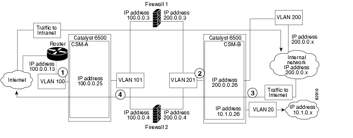
In a regular firewall configuration, firewalls connect to two different VLANs and are configured with IP addresses on the VLANs to which they connect. (See Figure 5-7.)
Figure 5-7 Regular Firewall Configuration Example
1
To intranet
VLAN 100
VLANs 101
2
To intranet
VLANs 201
VLAN 200 and 20
3
To Internet
VLAN 200 and 20
VLANs 201
4
To Internet
VLANs 101
VLAN 100
Figure 5-7 shows two regular firewalls (Firewall 1 and Firewall 2) located between two CSMs
(CSM A and CSM B). Traffic enters and exits the firewalls through shared VLANs (VLAN 101 and VLAN 201). Both regular firewalls have unique addresses on each shared VLAN.VLANs provide connectivity to the Internet (VLAN 100), the internal network (VLAN 200), and to internal server farms (VLAN 20).
The CSM balances traffic among regular firewalls as if they were real servers. Regular firewalls are configured in server farms with IP addresses like real servers. The server farms to which regular firewalls belong are assigned a load-balancing predictor and are associated with virtual servers.
Regular Firewall Configuration Example
The regular firewall configuration example contains two CSMs (CSM A and CSM B) installed in separate Catalyst 6000 family switches.
Note
Configuring CSM A (Regular Firewall Example)
To create the regular configuration example, perform the following configuration tasks for CSM A:
•
•
Note
Creating VLANs on Switch A
The example, shown in Figure 5-7, requires that you create two VLANs on Switch A.
Note
To configure VLANs on Switch A, perform this task:
Step 1
Switch-A(config)# vlan databaseEnters the VLAN mode1 .
Step 2
Switch-A(vlan)# vlan 100Creates VLAN 1002 .
Step 3
Switch-A(vlan)# vlan 101Creates VLAN 1013 .
1 Do this step on the switch console of the switch that contains CSM A.
2 VLAN 100 connects CSM A to the Internet.
3 VLAN 101 connects CSM A to the insecure side of the firewalls.
Configuring VLANs on CSM A
To configure the two VLANs, perform this task:
Step 1
Switch-A(config)# module csm 5Enters multiple module configuration mode and specifies that CSM A is installed in slot 5.
Step 2
Switch-A(config-module-csm)# vlan 100
client
Specifies VLAN 100 as the VLAN that is being configured, identifies it as a client VLAN, and enters VLAN configuration mode.
Step 3
Switch-A(config-slb-vlan-client)# ip
address 100.0.0.25 255.255.255.0
Specifies an IP address and netmask for VLAN 100.
Step 4
Switch-A(config-slb-vlan-client)# gateway
100.0.0.13
Configures a gateway IP address for the router on the Internet side of CSM A.
Step 5
Switch-A(config-slb-vlan-client)# exitReturns to multiple module configuration mode.
Step 6
Switch-A(config-module-csm)# vlan 101
server
Specifies VLAN 101 as the VLAN that is being configured, identifies it as a server VLAN, and enters VLAN configuration mode.
Step 7
Switch-A(config-slb-vlan-server)# ip
address 100.0.0.25 255.255.255.0
Specifies an IP address and netmask for VLAN 101.
Step 8
Switch-A(config-slb-vlan-server)# alias
100.0.0.20 255.255.255.0
Specifies an alias IP address and netmask for VLAN 1011 .
1 This step provides a target for CSM B to use in making a load-balancing decision.
Configuring Server Farms on CSM A
Note
To configure two server farms on CSM A, perform this task:
Step 1
Switch-A(config)# module csm 5Enters multiple module configuration mode and specifies that CSM A is installed in slot 5.
Step 2
Switch-A(config-module-csm)# serverfarm
FORWARD-SF
Creates and names the FORWARD-SF1 server farm (actually a forwarding policy) and enters server farm configuration mode.
Step 3
Switch-A(config-slb-sfarm)# no nat serverDisables the NAT of server IP addresses and port numbers2 .
Step 4
Switch-A(config-slb-sfarm)# predictor
forward
Forwards traffic by adhering to its internal routing tables rather than a load-balancing algorithm.
Step 5
Switch-A(config-slb-sfarm)# exitReturns to multiple module configuration mode.
Step 6
Switch-A(config-module-csm)# serverfarm
INSEC-SF
Creates and names the INSEC-SF3 server farm (which will contain firewalls as real servers) and enters server farm configuration mode.
Step 7
Switch-A(config-slb-sfarm)# no nat serverDisables the NAT of server IP address and port number4 .
Step 8
Switch-A(config-slb-sfarm)# predictor
hash address source 255.255.255.255
Selects a server using a hash value based on the source IP address5 .
Step 9
Switch-A(config-slb-sfarm)# real
100.0.0.3
Identifies Firewall 1 as a real server, assigns an IP address to its insecure side, and enters real server configuration submode.
Step 10
Switch-A(config-slb-real)# inserviceEnables the firewall.
Step 11
Switch-A(config-slb-real)# exitReturns to server farm configuration mode.
Step 12
Switch-A(config-slb-sfarm)# real
100.0.0.4
Identifies Firewall 2 as a real server, assigns an IP address to its insecure side, and enters real server configuration submode.
Step 13
Switch-A(config-slb-real)# inserviceEnables the firewall.
1 FORWARD-SF is actually a route forwarding policy, not an actual server farm, that allows traffic to reach the Internet (through VLAN 100); it does not contain any real servers.
2 This is a required step when configuring a server farm that contains a forwarding policy rather than real servers.
3 INSEC-SF contains (Firewall 1 and Firewall 2); their insecure-side IP addresses are configured as real servers in this server farm.
4 This is a required step when configuring a server farm that contains firewalls.
5 We recommend this step when configuring insecure-side firewall interfaces in a server farm.
Configuring Virtual Servers on CSM A
To configure two virtual servers on CSM A, perform this task:
Step 1
Switch-A(config)# module csm 5Enters multiple module configuration mode and specifies that the CSM A is installed in slot 5.
Step 2
Switch-A(config-module-csm)# vserver
FORWARD-VS
Specifies FORWARD-VS1 as the virtual server that is being configured and enters virtual server configuration mode.
Step 3
Switch-A(config-slb-vserver)# virtual
0.0.0.0 0.0.0.0 any
Specifies a match for any IP address and any protocol2 .
Step 4
Switch-A(config-slb-vserver))# vlan 101Specifies that the virtual server will only accept traffic arriving on VLAN 101, which is traffic arriving from the insecure side of the firewalls.
Step 5
Switch-A(config-slb-vserver)# serverfarm
FORWARD-SF
Specifies the server farm for this virtual server3 .
Step 6
Switch-A(config-slb-vserver)# inserviceEnables the virtual server.
Step 7
Switch-A(config-slb-vserver)# exitReturns to multiple module configuration mode.
Step 8
Switch-A(config-module-csm)# vserver
INSEC-VS
Specifies INSEC-VS4 as the virtual server that is being configured and enters virtual server configuration mode.
Step 9
Switch-A(config-slb-vserver)# virtual
200.0.0.0 255.255.255.0 any
Specifies the IP address, netmask, and protocol (any) for this virtual server5 .
Step 10
Switch-A(config-slb-vserver))# vlan 100Specifies that the virtual server will only accept traffic arriving on VLAN 100, which is traffic arriving from the Internet.
Step 11
Switch-A(config-slb-vserver)# serverfarm
INSEC-SF
Specifies the server farm for this virtual server6 .
Step 12
Switch-A(config-slb-vserver)# inserviceEnables the virtual server.
1 FORWARD-VS allows Internet traffic to reach the insecure side of the firewalls (through VLAN 101).
2 Client matching is only limited by VLAN restrictions (see Step 4).
3 This server farm is actually a forwarding predictor rather than an actual server farm containing real servers.
4 INSEC-VS allows traffic from the Internet to reach CSM A (through VLAN 101).
5 Clients reach the server farm represented by this virtual server through this address.
6 The server farm contains firewalls rather than real servers.
Configuring CSM B (Regular Firewall Example)
To create the regular configuration example, perform the following configuration tasks for CSM B:
•
•
Note
Creating VLANs on Switch B
Note
To create three VLANs on Switch B, perform this task:
Step 1
Switch-B(config)# vlan databaseEnters the VLAN mode1 .
Step 2
Switch-B(vlan)# vlan 201Creates VLAN 2012 .
Step 3
Switch-B(vlan)# vlan 200Creates VLAN 2003 .
Step 4
Switch-B(vlan)# vlan 20Creates VLAN 204 .
1 Do this step on the switch console of the switch that contains CSM B.
2 VLAN 201 provides the connection to the secure side of the firewalls.
3 VLAN 20 provides the connection to the internal server farms.
4 VLAN 200 provides the connection to the internal network.
Configuring VLANs on CSM B
To configure the three VLANs on CSM B, perform this task:
Step 1
Switch-B(config)# module csm 6Enters multiple module configuration mode and specifies that CSM B is installed in slot 6.
Step 2
Switch-B(config-module-csm)# vlan 201
server
Specifies VLAN 201 as the VLAN that is being configured, identifies it as a server VLAN, and enters VLAN configuration mode.
Step 3
Switch-B(config-slb-vlan-server)# ip
address 200.0.0.26 255.255.255.0
Specifies an IP address and netmask for VLAN 201.
Step 4
Switch-B(config-slb-vlan-server)# alias
200.0.0.20 255.255.255.0
Specifies an alias IP address and netmask for VLAN 2011 .
Step 5
Switch-B(config-slb-vlan-server)# exitReturns to VLAN configuration mode.
Step 6
Switch-B(config-module-csm)# vlan 20
server
Specifies VLAN 20 as the VLAN that is being configured, identifies it as a server VLAN, and enters VLAN configuration mode.
Step 7
Switch-B(config-slb-vlan-server)# ip
address 10.1.0.26 255.255.255.0
Specifies an IP address and netmask for VLAN 20.
Step 8
Switch-B(config-slb-vlan-server)# exitReturns to VLAN configuration mode.
Step 9
Switch-B(config-module-csm)# vlan 200
client
Specifies VLAN 200 as the VLAN that is being configured, identifies it as a client VLAN, and enters VLAN configuration mode.
Step 10
Switch-B(config-slb-vlan)# ip address
200.0.0.26 255.255.255.0
Specifies an IP address and netmask for VLAN 200.
1 This step provides a target for CSM A to use in making a load-balancing decision.
Configuring Server Farms on CSM B
Note
To configure two server farms on CSM B, perform this task:
Step 1
Switch-B(config)# module csm 6Enters multiple module configuration mode and specifies that CSM B is installed in slot 6.
Step 2
Switch-B(config-module-csm)# serverfarm
GENERIC-SF
Creates and names the GENERIC-SF1 server farm and enters server farm configuration mode.
Step 3
Switch-B(config-slb-sfarm)# real
10.1.0.101
Identifies a server in the internal server farm as a real server, assigns it an IP address, and enters real server configuration submode.
Step 4
Switch-B(config-slb-real)# inserviceEnables the real server.
Step 5
Switch-B(config-slb-real)# exitReturns to server farm configuration mode.
Step 6
Switch-B(config-slb-sfarm)# real
10.1.0.102
Identifies a server in the internal server farm as a real server, assigns it an IP address, and enters real server configuration submode.
Step 7
Switch-B(config-slb-real)# inserviceEnables the real server.
Step 8
Switch-B(config-slb-real)# exitReturns to server farm configuration mode.
Step 9
Switch-B(config-slb-sfarm)# exitReturns to multiple module configuration mode.
Step 10
Switch-B(config-module-csm)# serverfarm
SEC-SF
Creates and names the SEC-SF2 server farm and enters server farm configuration mode.
Step 11
Switch-B(config-slb-sfarm)# no nat serverDisables the NAT of server IP address and port number3 .
Step 12
Switch-B(config-slb-sfarm)# predictor
hash address destination 255.255.255.255
Selects a server using a hash value based on the destination IP address4 .
Step 13
Switch-B(config-slb-sfarm)# real
200.0.0.3
Identifies Firewall 1 as a real server, assigns an IP address to its insecure side, and enters real server configuration submode.
Step 14
Switch-B(config-slb-real)# inserviceEnables the firewall.
Step 15
Switch-B(config-slb-real)# exitReturns to server farm configuration mode.
Step 16
Switch-B(config-slb-sfarm)# real
200.0.0.4
Identifies Firewall 2 as a real server, assigns an IP address to its insecure side, and enters real server configuration submode.
Step 17
Switch-B(config-slb-real)# inserviceEnables the firewall.
1 GENERIC-SF contains the real servers in the internal server farm.
2 SEC-SF contains (firewall 1 and firewall 2)-their secure-side IP addresses are configured as real servers in this server farm.
3 This is a required step when configuring a server farm that contains firewalls.
4 We recommend this step when configuring secure-side firewall interfaces in a server farm.
Configuring Virtual Servers on CSM B
To configure three virtual servers on CSM B, perform this task:
Step 1
Switch-B(config)# module csm 6Enters multiple module configuration mode and specifies that CSM B is installed in slot 6.
Step 2
Switch-B(config-module-csm)# vserver
GENERIC-VS
Specifies GENERIC-VS1 as the virtual server that is being configured and enters virtual server configuration mode.
Step 3
Switch-B(config-slb-vserver)# virtual
200.0.0.127 tcp 0
Specifies the IP address, protocol (TCP), and port (0=any) for this virtual server2 .
Step 4
Switch-B(config-slb-vserver))# vlan 201Specifies that the virtual server will only accept traffic arriving on VLAN 201, which is traffic arriving from the secure side of the firewalls.
Step 5
Switch-B(config-slb-vserver)# serverfarm
GENERIC-SF
Specifies the server farm for this virtual server3 .
Step 6
Switch-B(config-slb-vserver)# inserviceEnables the virtual server.
Step 7
Switch-B(config-slb-vserver)# exitReturns to multiple module configuration mode.
Step 8
Switch-B(config-module-csm)# vserver
SEC-20-VS
Specifies SEC-20-VS4 as the virtual server that is being configured and enters virtual server configuration mode.
Step 9
Switch-B(config-slb-vserver)# virtual
200.0.0.0 255.255.255.0 any
Specifies the IP address, netmask, and protocol (any) for this virtual server 2.
Step 10
Switch-B(config-slb-vserver))# vlan 20Specifies that the virtual server will only accept traffic arriving on VLAN 20, which is traffic arriving from the internal server farms.
Step 11
Switch-B(config-slb-vserver)# serverfarm
SEC-SF
Specifies the server farm for this virtual server5 .
Step 12
Switch-B(config-slb-vserver)# inserviceEnables the virtual server.
Step 13
Switch-B(config-slb-vserver)# exitReturns to multiple module configuration mode.
Step 14
Switch-B(config-module-csm)# vserver
SEC-200-VS
Specifies SEC-20-VS6 as the virtual server that is being configured and enters virtual server configuration mode.
Step 15
Switch-B(config-slb-vserver)# virtual
200.0.0.0 255.255.255.0 any
Specifies the IP address, netmask, and protocol (any) for this virtual server 2.
Step 16
Switch-B(config-slb-vserver))# vlan 200Specifies that the virtual server will only accept traffic arriving on VLAN 200, which is traffic arriving from the internal network.
Step 17
Switch-B(config-slb-vserver)# serverfarm
SEC-SF
Specifies the server farm for this virtual server 5.
Step 18
Switch-B(config-slb-vserver)# inserviceEnables the virtual server.
1 GENERIC-VS allows traffic from the internal server farms and the internal network that is destined for the Internet to reach the secure side of the firewalls (through VLAN 101).
2 Clients reach the server farm represented by this virtual server through this address.
3 The server farm exists in the internal server farms network.
4 SEC-20-VS allows traffic from the Internet to reach the internal server farms (through VLAN 20).
5 The server farm contains firewalls rather than real servers.
6 SEC-200-VS allows traffic from the Internet to reach the internal network (through VLAN 20).
Configuring Generic Header Parsing
In software release 2.1(1), the CSM supports generic HTTP request header parsing. The HTTP request header contains fields that describe how content should be formatted to meet the user's requirements.
The CSM uses the information it learns by parsing and matching fields in the HTTP header along with policy information to make load-balancing decisions. For example, by parsing the browser-type field in the HTTP header, the CSM can determine if a user is accessing the content with a mobile browser and can select a server that contains content formatted for a mobile browser.
An example of a HTTP Get request header record is as follows:
GET /?u HTTP/1.1<0D><0A>Accept: image/gif, image/x-xbitmap, image/jpeg, image/pjpeg<0D><0A>Referer: http://www.yahoo.com/<0D><0A>Accept-Language: en-us<0D><0A>Accept-Encoding: gzip, deflate<0D><0A>User-Agent: Mozilla/4.0 (compatible; MSIE 5.0; Windows NT; DigExt)<0D><0A>Host: finance.yahoo.com<0D><0A>Connection: Keep-Alive<0D><0A>Cookie: B=51g3cjstaq3vm; Y=1<0D><0A><0D><0A>Configuring Generic Header Parsing
You configure generic header parsing by entering commands that instruct the CSM to perform policy matching on fields in the HTTP header. These sections describe how to configure generic header parsing on the CSM:
•
•
•
•
Creating a Map for the HTTP Header
Using the map command, you create a map group with the type HTTP header. Entering the map command places you in a submode where you can specify the header fields and values for CSM to search for in the request.
To create a map for the HTTP header, perform this task:
Router(config-module-csm)# map name headerCreates and names a HTTP header map group.
Note
Specifying Header Fields and Match Values
Using the match command, you specify the name of the field and corresponding value for the CSM to match when receiving an HTTP request.
To specify head fields and match values, perform this task:
Note
Assigning an HTTP Header Map to a Policy
In policy submode, you specify the header map to include in that policy. The header map contains the HTTP header criteria to be included in a policy.
To assign an HTTP header map to a policy, perform this task:
Step 1
Router(config-module-csm)#
policy policy-name
Creates a policy.
Step 2
Router(config-slb-policy)#
header-map name
Assigns an HTTP header map to a policy.
Note
Assigning the Policy to a Virtual Server
In virtual server submode, specify the name of the policy that has the header map assigned, using the ip slb vserver virtserver-name command.
To specify a policy with a header map assigned, perform this task:
Step 1
Router(config-module-csm)#
vserver virtserver-name
Configures a virtual server.
Step 2
Router(config-slb-policy)# header-map name
Assigns an HTTP header map to a policy.
This example shows how to configure generic header parsing:
Router(config)# mod csm 2Router(config-module-csm)# !!!configure generic header mapRouter(config-module-csm)# map map2 headerRouter(config-slb-map-heaer)# $col http header Host header-value *.yahoo.comRouter(config-slb-map-header)# !!! configure serverfarmRouter(config-slb-map-header)# serverfarm farm2Router(config-slb-sfarm)# real 10.1.0.105Router(config-slb-real)# inserviceRouter(config-slb-real)# exitRouter(config-slb-sfarm)# exitRouter(config-module-csm)# !!! configurate policyRouter(config-module-csm)# policy pc2Router(config-slb-policy)# serverfarm farm2Router(config-slb-policy)# header-map map2Router(config-slb-policy)# exitRouter(config-module-csm)# !!! config vserverRouter(config-module-csm)# vserver vs2Router(config-slb-vserver)# virtual 10.1.0.82 tcp 80Router(config-slb-vserver)# slb-policy pc2Router(config-slb-vserver)# inserviceRouter(config-slb-vserver)# endRouter(config)# show module csm 2 map detConfiguring Persistent Connections
The CSM allows HTTP connections to be switched based on a URL, cookies, or other fields contained in the HTTP header. Persistent connection support in the CSM allows for each successive HTTP request in a persistent connection to be switched independently. As a new HTTP request arrives, it may be switched to the same server as the prior request, it may be switched to a different server, or it may be reset to the client preventing that request from being completed.
In software release 2.1(1), the CSM supports HTTP 1.1 persistence. This features allows browsers to send multiple HTTP requests on a single persistent connection. After a persistent connection is established, the server keeps the connection open for a configurable interval, anticipating that it may receive more requests from the same client. Persistent connections eliminate the overhead involved in establishing a new TCP connection for each request.
HTTP 1.1 persistence is enabled by default on all virtual servers configured with Layer 7 policies. To disable persistent connections, enter the no persistent rebalance command. To enable persistent connection, enter the persistent rebalance command.
This example shows how to configure persistent connection:
Router# conf tEnter configuration commands, one per line. End withCNTL/Z.Router(config)# mod csm 2!!! configuring serverarmRouter(config-module-csm)# serverfarm sf3Router(config-slb-sfarm)# real 10.1.0.105Router(config-slb-real)# inservice!!! configuring vserverRouter(config-slb-real)# vserver vs3Router(config-slb-vserver)# virtual 10.1.0.83 tcp 80Router(config-slb-vserver)# persistent rebalanceRouter(config-slb-vserver)# serverfarm sf3Router(config-slb-vserver)# inserviceRouter(config-slb-vserver)# endConfiguring Connection Redundancy
Connection redundancy prevents open connections from hanging when the active CSM fails and the standby CSM becomes active. With connection redundancy, the active CSM replicates forwarding information to the standby CSM for each connection that is to remain open when the active CSM fails over to the standby CSM.
To configure connection redundancy, perform this task:
This example shows how to set fault tolerance for connection redundancy:
Router(config-module-csm)# vserver VS_LINUX-TELNETRouter(config-slb-vserver)# virtual 10.6.0.100 tep telnetRouter(config-slb-vserver)# serverfarm SF_NONATRouter(config-slb-vserver)# sticky 100 group 35Router(config-slb-vserver)# replicate csrp stickyRouter(config-slb-vserver)# replicate csrp connectionRouter(config-slb-vserver)# inserviceRouter(config-slb-vserver)# exitRouter(config-module-csm)# ft group 90 vlan 111Router(config-slb-ft)# priority 10Router(config-slb-ft)# failover 3Router(config-slb-ft)# preemptRouter(config-slb-ft)# exitConfiguring a Hitless Upgrade
A hitless upgrade allows you to upgrade to a new version without any major service disruption due to the downtime for the upgrade. To configure a hitless upgrade, perform these steps:
Step 1
Step 2
Step 3
The standby CSM boots as standby with the new release. If you have sticky backup enabled, keep the standby CSM in standby mode for at least 5 minutes.
Step 4
Step 5
When the active CSM reboots, the standby CSM becomes the new active CSM and takes over the service responsibility.
Step 6
Configuring SNMP Traps for Real Servers
When enabled, an SNMP trap is sent to an external management device each time a real server changes its state (for example, each time a server is taken in or out of service). The trap contains an Object Identifier (OID) that identifies it as a real-server trap.
Note
The trap also contains a message describing the reason for the server state change.
To configure SNMP traps for real servers, perform this task:
![]()
![]()
![]()
![]()
![]()
![]()
![]()
![]()
Posted: Mon Mar 21 15:43:33 PST 2005
All contents are Copyright © 1992--2005 Cisco Systems, Inc. All rights reserved.
Important Notices and Privacy Statement.