cc/td/doc/product/lan/cat6000/6000hw
hometocprevnextglossaryfeedbacksearchhelp
PDF

Table Of Contents

Multilayer Switch Module


Multilayer Switch Module


This chapter describes the Multilayer Switch Module (MSM) (WS-X6302-MSM).

The Multilayer Switch Module provides multiprotocol routing for the switch Ethernet interfaces. Cisco IOS features available for the MSM are listed in Table 5-1.

Table 5-1 Cisco IOS Features for the Multilayer Switch Module 

Feature
Description

Layer 3 forwarding

Wire speed IP, IP multicast, and IPX routing between VLANs

Support for up to 64K entries for IP network prefixes, IP unicast and multicast addresses, IPX network numbers, and MAC addresses

IP precedence-based IP forwarding

Forwarding information base (FIB) and adjacency database support as defined in other Cisco routers

Destination or destination/source-based load sharing among equal cost paths

Layer 3 routing protocols

Static IP routing

IP routing protocols such as Internet Group Management Protocol (IGRP), Enhanced Interior Gateway Routing Protocol (EIGRP), Open Shortest Path First (OSPF), Routing Information Protocol (RIP), and RIP-2

IP multicast routing protocols such as Protocol Independent Multicast (PIM) (sparse and dense mode) and Distance Vector Multicast Routing Protocol (DVMRP)

IPX routing protocols such as RIP and EIGRP

Layer 3-related protocols

IGMP v1 and v2

IGMP snooping

Cisco Group Multicast Protocol (CGMP) server support

Full ICMP support

Gateway Discovery Protocol (GDP)

Internet Control Message Protocol (ICMP) Router Discovery Protocol (IRDP)

Enhanced services

Integrated routing and bridging (IRB)

Standard Domain Naming System (DNS) support

Dynamic Host Configuration Protocol (DHCP) and Boot Protocol (BOOTP) relay


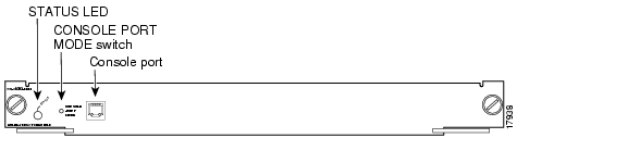
The MSM front panel features are shown in Figure 5-1 and are described in Table 5-2.

Figure 5-1 Multilayer Switch Module (WS-X6302-MSM)

The STATUS LED shows the results of the initialization and its dialog with the supervisor engine. Table 5-2 describes the LED operation.

For detailed information on the supervisor engine LEDs, refer to the Catalyst 6500 Series Supervisor Engine Installation Guide.

Table 5-2 Multilayer Switch Module STATUS LED

Color/State
Description

Green

All diagnostics pass; the module is operational.

Orange

The module is booting or running diagnostics.


An overtemperature condition has occurred. (A minor temperature threshold has been exceeded during environmental monitoring.)

Red

A diagnostic test has failed; the module is not operational.


An overtemperature condition has occurred. (A major temperature threshold has been exceeded during environmental monitoring.)


The CONSOLE PORT MODE switch allows you to connect a terminal to the MSM using either a Catalyst 5000 family Supervisor Engine III console cable or the console cable and adapters provided with the switch. You also can connect a modem to the console port using the cable and adapter provided with the switch.


Note Use a paper clip or a small, pointed object to access the CONSOLE PORT MODE switch.


Use the CONSOLE PORT MODE switch as follows:

Mode 1—Place the switch in the in position (factory default position) to connect a terminal to the console port using the console cable and DTE adapter (labeled "Terminal") that shipped with the switch.

You can also use this mode to connect a modem to the console port using the console cable and DCE adapter (labeled "Modem") that shipped with the switch.

Mode 2—Place the switch in the out position to connect a terminal to the console port using the Catalyst 5000 family Supervisor Engine III console cable (not provided).


hometocprevnextglossaryfeedbacksearchhelp

Posted: Thu Dec 30 00:10:43 PST 2004
All contents are Copyright © 1992--2004 Cisco Systems, Inc. All rights reserved.
Important Notices and Privacy Statement.