cc/td/doc/product/lan/cat6000/6000hw
hometocprevnextglossaryfeedbacksearchhelp
PDF

Table Of Contents

ATM Modules

1-Port OC-12 ATM Module (WS-X6101-OC12-MMF)

1-Port OC-12 ATM Module (WS-X6101-OC12-SMF)

ATM Module LEDs


ATM Modules


This chapter describes the ATM Modules, and it contains the following sections

1-Port OC-12 ATM Module (WS-X6101-OC12-MMF)

1-Port OC-12 ATM Module (WS-X6101-OC12-SMF)

ATM Module LEDs


Note These modules are Class 1 laser products. Refer to the Regulatory Compliance and Safety Information for the Catalyst 6500 Series Switches for information on working with lasers.


1-Port OC-12 ATM Module (WS-X6101-OC12-MMF)

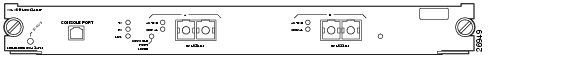
The 1-port ATM module (WS-X6101-OC12-MMF) provides one direct connection and one standby connection between the ATM network and the switch using two multimode, SC, fiber-optic connectors. (See Figure 3-1.)

The CONSOLE PORT allows you to access the switch either locally (with a console terminal) or remotely (with a modem). The CONSOLE PORT is an EIA/TIA-232 asynchronous, serial connection with hardware flow control and an RJ-45 connector.

The CONSOLE PORT mode switch allows you to attach either a terminal or a modem to the CONSOLE PORT.


Note Use a ballpoint pen tip or other small, pointed object to access the CONSOLE PORT MODE switch.


Use the CONSOLE PORT MODE switch as follows:

Mode 1—Switch in the in position (factory default). Use this mode to connect a terminal to the console port using a console cable and a DTE adapter. You can also use this mode to connect a modem to the console port.

Mode 2—Switch in the out position. Use this mode to connect a terminal to the console port using the Catalyst 5000 family Supervisor Engine III console cable (not provided).

Figure 3-1 ATM OC-12 Module (MMF) (WS-X6101-OC12-MMF)

The front panel LEDs are described in Table 3-1.

1-Port OC-12 ATM Module (WS-X6101-OC12-SMF)

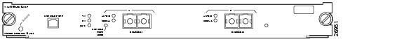
The 1-port ATM module (WS-X6101-OC12-SMF) provides one direct connection and one standby connection between the ATM network and the switch using two single-mode, SC, fiber-optic connectors. (See Figure 3-2.)

The CONSOLE PORT allows you to access the switch either locally (with a console terminal) or remotely (with a modem). The CONSOLE PORT is an EIA/TIA-232 asynchronous, serial connection with hardware flow control and an RJ-45 connector.

The CONSOLE PORT MODE switch allows you to attach either a terminal or a modem to the console port.


Note Use a ballpoint pen tip or other small, pointed object to access the CONSOLE PORT MODE switch.


Use the CONSOLE PORT MODE switch as follows:

Mode 1—Switch in the in position (factory default). Use this mode to connect a terminal to the CONSOLE PORT using a console cable and a DTE adapter. You can also use this mode to connect a modem to the console port.

Mode 2—Switch in the out position. Use this mode to connect a terminal to the CONSOLE PORT using the Catalyst 5000 family Supervisor Engine III console cable (not provided).

Figure 3-2 ATM OC-12 Module (SMF) (WS-X6101-OC12-SMF)

The front panel LEDs are described in Table 3-1.

ATM Module LEDs

The ATM module front-panel LEDs are described in Table 3-1.

Table 3-1 ATM Module LEDs 

LED
Color/State
Description

STATUS

Green

All diagnostics pass; the module is operational.


Orange

The module is booting or running diagnostics.

A fault occurred during the initialization sequence.

An overtemperature condition has occurred. (A minor temperature threshold has been exceeded during environmental monitoring.)


Red

The module is resetting. (The switch has just been powered on or the module has been hot inserted.)

An overtemperature condition has occurred. (A major temperature threshold has been exceeded during environmental monitoring.)

If the module fails to download code and configuration information successfully during the initial reset, the LED stays red; the module does not come online.


Off

The module is not receiving power.

TX (transmit)

Green

The port is transmitting a packet (the LED is lit for approximately 50 milliseconds).

RX (receive)

Green

The port is receiving a packet (the LED is lit for approximately 50 milliseconds).

LINK

Green

The port is active (the link is connected and operational).


Orange

The module or port is disabled through the CLI command or the module is initializing.


Flashing orange

The port is faulty and has been disabled.


Off

The port is not active or the link is not connected.

ACTIVE

Green

The port is active (the link is connected and operational).


Off

The port is the standby port.

SIGNAL

Green

The active port is receiving a valid signal level through the fiber-optic cable; this condition does not indicate valid framing.


hometocprevnextglossaryfeedbacksearchhelp

Posted: Thu Dec 30 00:07:49 PST 2004
All contents are Copyright © 1992--2004 Cisco Systems, Inc. All rights reserved.
Important Notices and Privacy Statement.