|
|

Catalyst 5000 family switches support the Route Switch Module (RSM) and the RSM/Versatile Interface Processor 2 (VIP2). This chapter describes the RSM and consists of these sections:
For detailed RSM installation and configuration information, refer to the Catalyst 5000 Family Route Switch Module Installation and Configuration Note and the Software Configuration Guide for your switch. For detailed RSM/VIP2 installation and configuration information, refer to the Route Switch Module Catalyst VIP2-15 and VIP2-40 Installation and Configuration Note.
The RSM is a router module running IOS router software that plugs directly into the Catalyst 5000 family switch backplane, providing multiprotocol routing for the Catalyst 5000 family Ethernet interfaces.
The RSM requires Catalyst 5000 family supervisor engine module software release 2.3(1) or later and IOS software release 11.2(7)P or later.
From the perspective of the Catalyst 5000 family switches, the RSM appears as a module with a single trunked port and one Media Access Control (MAC) address. From the perspective of the user, the RSM has one port. This port is unlike other Catalyst 5000 family module ports in that it has no external attributes, such as media type or speed.
The RSM front panel (Figure 7-1) has the following features:

The RSM LEDs are described in Table 7-1.
| LED | State | Description |
|---|---|---|
STATUS |
| Indicates a series of self-tests and diagnostic tests. |
| Green | All the tests pass. |
| Red | A test other than an individual port test failed. |
| Orange | System boot, self-test diagnostics running, or the module is disabled. |
CPU HALT |
| Indicates the RSM status. |
| On | Normal operation. |
| Off | The system detected a processor hardware failure. |
ENABLED |
| Indicates the RSM operational status. |
| On | The IP microcode is loaded and the RSM is operational. |
PCMCIA SLOT 0 and SLOT 1 |
| Indicates when slot 1 and slot 0 PCMCIA devices are accessed by the RSM. |
| On | Device in PCMCIA slot is accessed by RSM. |
TX1 |
| Indicates the port transmits. |
| Green | The port is transmitting a packet (LED is lit for approximately 50 ms). |
RX2 |
| Indicates the port receives. |
| Green | The port is receiving a packet (LED is lit for approximately 50 ms3). |
| 1TX=transmit 2RX=receive 3ms = milliseconds |
The RSM provides multiprotocol routing for the Catalyst 5000 family switch Ethernet interfaces. Table 7-2 lists the IOS features available for the RSM.
| Item | Feature |
|---|---|
LAN support (routed protocols) | IP, IPX/SPX1, and AppleTalk |
| IP | |
Routing protocols | Routing Information Protocol |
Routing features | Static routing |
IP control and management services | Internet Control Message Protocol services |
Files transfers | Trivial File Transfer Protocol |
| IPX/SPX | |
Routing protocols | Routing Information Protocol |
Routing features | Get Nearest Server |
Encapsulation techniques | 802.3 (Novell-ether) |
| AppleTalk (Phases 1 and 2) | |
Routing protocols | AppleTalk ARP6 |
Routing features | Packet filters |
DECnet | Phase IV and Phase V |
Banyan VINES | N/A |
You can use the RSM as a standalone interVLAN router or you can enhance it by adding a Catalyst VIP2 module to provide direct external network connections through a variety of media with the same port adapters used on Cisco 7500 series routers. The RSM/VIP2 combination provides routing between Catalyst VIP2 port adapters and between VLANs and Catalyst VIP2 port adapters. The Catalyst VIP2 module supports any combination of available Catalyst VIP2 port adapter-based network interface types. When you use the RSM with the Catalyst VIP2 module, the combination is a double-wide module that occupies two contiguous slots in the chassis.
The Catalyst VIP2 module requires that the RSM runs IOS release 11.2(9)P or later, and that the supervisor engine runs Catalyst 5000 family software release 2.3(1) or later.
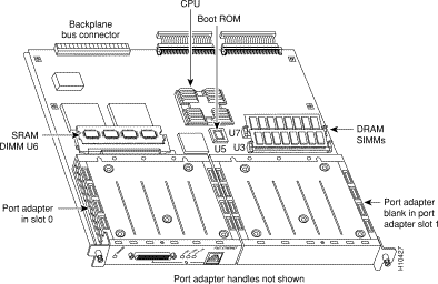
Figure 7-2 shows a Catalyst VIP2 module with a port adapter installed.

The current Catalyst VIP2 products have the following dynamic random-access memory (DRAM) and static random-access memory (SRAM) configurations:
The Catalyst VIP2-15 upgrade option (Catalyst VIP215/40-UPG=) allows you to upgrade to 2-MB SRAM and 32-MB DRAM.
Software licenses are included to use Distributed Switching and Distributed Services.
The port adapters attach to the Catalyst VIP2 motherboard. (See Figure 7-2.) Each port adapter contains the physical connections for the Catalyst VIP2 interface types to connect to your network. For the available electrical interface supported by the Catalyst VIP2 module, refer to the Cisco Products Catalog.
 | Caution Catalyst VIP2 modules with a single port adapter must have a blank port adapter installed to maintain compliance with electromagnetic interference (EMI) emissions standards and chassis airflow requirements. Each port adapter has one Phillips-head screw that secures it to its port adapter slot. |
For detailed information on installing and configuring the RSM/VIP2 modules, refer to the Route Switch Module Catalyst VIP2-15 and VIP2-40 Installation and Configuration Note.
![]()
![]()
![]()
![]()
![]()
![]()
![]()
![]()
Posted: Mon Feb 21 14:45:40 PST 2000
Copyright 1989 - 2000©Cisco Systems Inc.