|
|

The Catalyst 4224 Access Gateway Switch (Catalyst 4224) provides Voice-over-IP (VoIP) gateway applications for a micro branch office. This section provides comprehensive information on how to configure VoIP on your Catalyst 4224.
This section contains the following topics:
Before you can configure your Catalyst 4224 to use VoIP, you need to perform the following tasks:
After you have analyzed your dial plan and decided how to integrate it into your existing IP network, you are ready to configure your network devices to support VoIP.
To configure VoIP on your Catalyst 4224, perform the following steps:
Step 2 (Optional) If you plan to run Voice over Frame Relay, you need to consider certain factors so that VoIP runs smoothly. For example, a public Frame Relay cloud provides no guarantees for QoS. See the "Configure Frame Relay for VoIP" section for information about deploying VoIP over Frame Relay.
Step 3 Use the num-exp command to configure number expansion if your telephone network is configured so that you can reach a destination by dialing only an extension number of the full E.164 telephone number. See the "Configure Number Expansion" section for information about number expansion.
Step 4 Use the dial-peer voice command to define dial peers and switch to the dial-peer configuration mode. See the "Configure Dial Peers" section and the "Additional VoIP Dial-Peer Configurations" section for additional information about configuring dial peers and dial-peer characteristics.
Step 5 Configure your Catalyst 4224 to support voice ports. See the "Configure Voice Ports" section for information about configuring voice ports.
You need to have a well engineered end-to-end network when running delay-sensitive applications such as VoIP. Fine-tuning your network to adequately support VoIP involves a series of protocols and features to improve QoS. It is beyond the scope of this document to explain the specific details relating to wide-scale QoS deployment.
Cisco IOS software provides many tools for enabling QoS on your network backbone. These tools include Random Early Detection (RED), Weighted Random Early Detection (WRED), Fancy Queuing (meaning custom, priority, or weighted fair queuing), and IP precedence. To configure your IP network for real-time voice traffic, you need to consider the entire scope of your network and then select the appropriate QoS tool or tools.
To improve voice network performance, QoS must be configured throughout your network, not just on your Catalyst 4224 running VoIP. Not all QoS techniques are appropriate for all network routers. Edge routers and backbone routers in your network do not necessarily perform the same operations, and the QoS tasks they perform might differ as well. To configure your IP network for real-time voice traffic, you need to consider the functions of both edge and backbone routers in your network and then select the appropriate QoS tool or tools.
In general, edge routers perform the following QoS functions:
In general, backbone routers perform the following QoS functions:
Scalable QoS solutions require cooperative edge and backbone functions.
Although not mandatory, some QoS tools can be valuable in fine-tuning your network to support real-time voice traffic. To configure your IP network for QoS, perform one or more of the following tasks:
Each of these tasks is discussed in the following sections.
Resource Reservation Protocol (RSVP) enables routers to reserve enough bandwidth on an interface to provide reliable, high-quality performance. RSVP allows end systems to request a particular QoS from the network. Real-time voice traffic requires network consistency. Without consistent QoS, real-time traffic can experience jitter, insufficient bandwidth, delay variations, or information loss. RSVP works in conjunction with current queuing mechanisms. The interface queuing mechanism (such as weighted fair queuing or WRED) must implement the reservation.
RSVP works well on PPP, HDLC, and similar serial line interfaces. It does not work well on multiaccess LANs. RSVP can be equated to a dynamic access list for packet flows.
You should configure RSVP to ensure QoS if the following conditions describe your network:
To minimally configure RSVP for voice traffic, you must enable RSVP on each interface where priority is required.
By default, RSVP is disabled so that it is backward compatible with systems that do not implement RSVP. To enable RSVP for IP on an interface, use the following command:
ip rsvp bandwidth [interface-kbps] [single-flow-kbps]
interface-kbps represents the maximum amount of bandwidth, in kbps, that may be allocated by RSVP flows and single-flow-kbps represents the maximum amount of bandwidth, in kbps, that may be allocated to a single flow. The range for both arguments is from 1 to 10,000,000.
This command starts RSVP and sets the bandwidth and single-flow limits. The default maximum bandwidth is up to 75 percent of the bandwidth available on the interface. By default, the amount reservable by a flow can be up to the entire reservable bandwidth.
On subinterfaces, RSVP applies to the more restrictive of the available bandwidths of the physical interface and the subinterface.
Reservations on individual circuits that do not exceed the single flow limit normally succeed. However, if reservations have been made on other circuits adding up to the line speed, and a reservation is made on a subinterface that itself has enough remaining bandwidth, the reservation will be refused. The reason the reservation will be refused is because the physical interface lacks supporting bandwidth.
A Cisco 1750 running VoIP and configured for RSVP requests allocations by using the following formula:
bps = packet_size + ip/udp/rtp header size x 50 per second
For the codec standard G.729, wherein voice is coded into 8-kbps streams, the allocation works out to be 24,000 bps. For G.711, the allocation is 80,000 bps.
For more information about configuring RSVP, refer to the "Configuring RSVP" section of the Network Protocols Configuration Guide, Part 1 for Cisco IOS Release 12.0 T.
The following example enables RSVP and sets the maximum bandwidth to 100 kbps and the maximum bandwidth per single request to 32 kbps. The example presumes that both VoIP dial peers have been configured.
After enabling RSVP, you must also use the req-qos dial-peer configuration command to request an RSVP session on each VoIP dial peer. Otherwise, no bandwidth is reserved for voice traffic.
Multiclass multilink Point-to-Point Protocol (PPP) interleaving allows large packets to be multilink-encapsulated and fragmented into smaller packets to satisfy the delay requirements of real-time voice traffic. Small real-time packets, which are not multilink-encapsulated, are transmitted between fragments of the large packets.
The interleaving feature also provides a special transmit queue for the smaller, delay-sensitive packets, enabling them to be transmitted earlier than other flows. Interleaving provides the delay bounds for delay-sensitive voice packets on a slow link that is used for other best-effort traffic.
In general, multilink PPP with interleaving is used in conjunction with weighted fair queuing and RSVP or IP precedence to ensure voice packet delivery. Use multilink PPP with interleaving and weighted fair queuing to define how data is managed; use RSVP or IP precedence to give priority to voice packets.
You should configure multilink PPP if the following conditions describe your network:
You can configure multilink PPP support for interleaving on virtual templates, dialer interfaces, and ISDN Basic Rate Interface (BRI) or Primary Rate Interface (PRI) interfaces. To configure interleaving, perform the following tasks:
To configure multilink PPP and interleaving on a configured and operational interface or virtual interface template, use the following interface configuration commands:
 |
Note You can use the ip rtp reserve command instead of configuring RSVP. If you configure RSVP, this command is not required. |
For more information about multilink PPP, refer to the "Configuring Media-Independent PPP and Multilink PPP" section in the Dial Solutions Configuration Guide for Cisco IOS Release 12.0 T.
The following example defines a virtual interface template that enables multilink PPP with interleaving and a maximum real-time traffic delay of 20 milliseconds, and then applies that virtual template to the multilink PPP bundle:
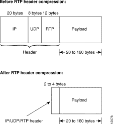
Real-Time Transport Protocol (RTP) is used for carrying audio traffic in packets over an IP network. RTP header compression compresses the RTP/UDP/IP header in an RTP data packet from 40 bytes to approximately 2 to 4 bytes, in most cases, as shown in Figure 6-1.
This compression feature is beneficial if you are running VoIP over slow links. Enabling compression on both ends of a low-bandwidth serial link can greatly reduce the network overhead if there is a lot of RTP traffic on that slow link.
Typically, an RTP packet has a payload of approximately 20 to 160 bytes for audio applications that use compressed payloads. RTP header compression is especially beneficial when the RTP payload size is small (for example, compressed audio payloads between 20 and 50 bytes).
You should configure RTP header compression if the following conditions describe your network:
Perform the following tasks to configure RTP header compression for VoIP. The first task is required, but the second task is optional.
You need to enable compression on both ends of a serial connection. To enable RTP header compression, use the following interface configuration command:
If you include the passive keyword, the software compresses outgoing RTP packets only if incoming RTP packets on the same interface are compressed. If you use the command without the passive keyword, the software compresses all RTP traffic.
By default, the software supports a total of 16 RTP header compression connections on an interface. To specify a different number of RTP header compression connections, use the following interface configuration command:
The following example enables RTP header compression for a serial interface:
For more information about RTP header compression, see the "Configuring IP Multicast Routing" section of the Network Protocols Configuration Guide, Part 1 for Cisco IOS Release 12.0 T.
Some QoS features, such as IP RTP reserve and custom queuing, are based on the transport protocol and the associated port number. Real-time voice traffic is carried on UDP ports ranging from 16384 to 16624. This range is derived from the following formula:
16384 + (4 x number of voice ports in the c4224)
Custom queuing and other methods for identifying high-priority streams should be configured for these port ranges. For more information about custom queuing, refer to the "Managing System Performance" section in the Configuration Fundamentals Configuration Guide for Cisco IOS Release 12.0 T.
Weighted fair queuing ensures that queues do not starve for bandwidth and that traffic gets predictable service. Low-volume traffic streams receive preferential service, while high-volume traffic streams share the remaining capacity, obtaining equal or proportional bandwidth.
In general, weighted fair queuing is used in conjunction with multilink PPP with interleaving and RSVP or IP precedence to ensure voice packet delivery. Use weighted fair queuing with multilink PPP to define how data is managed; use RSVP or IP precedence to give priority to voice packets. For more information about weighted fair queuing, refer to the "Managing System Performance" section in the Configuration Fundamentals Configuration Guide for Cisco IOS Release 12.0 T.
In most corporate environments, the telephone network is configured so that you can reach a destination by dialing only a portion (an extension number) of the full E.164 telephone number. You can configure VoIP to recognize extension numbers and expand them into their full E.164 dialed number by using two commands in tandem: destination-pattern and num-exp. Before you configure these two commands, it helps to map individual telephone extensions with their full E.164 dialed numbers. You can do this by creating a number expansion table.
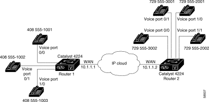
The example depicted in Figure 6-2 pertains to a small company that decides to use VoIP to integrate its telephony network with its existing IP network. The destination pattern (or expanded telephone number) associated with Catalyst 4224 1 (left of the IP cloud) is 408-555-xxxx, where xxxx identifies the individual dial peers by extension. The destination pattern (or expanded telephone number) associated with Catalyst 4224 2 (right of the IP cloud) is 729-555-xxxx.
Table 6-1 shows the number expansion table for this scenario.
Table 6-1 Sample Number Expansion Table
|
Note You can use a period (.) to represent variables, such as extension numbers, in a telephone number. A period is similar to a wildcard, which matches any entered digit. |
The information included in this example needs to be configured on both Catalyst 4224 1 and Catalyst 4224 2. In this configuration, Catalyst 4224 1 can call any number string that begins with the digits 17295552 or 17295553 to connect to Catalyst 4224 2. Catalyst 4224 2 can call any number string that begins with the digits 14085551 to connect to Catalyst 4224 1.
To define how to expand an extension number into a particular destination pattern, use the following global configuration command:
num-exp extension-number extension-string
extension-number represents the digit(s) defining an extension number to be expanded, whereas extension-string represents the digit(s) defining an extension string to be expanded.
Use the show num-exp command to verify that you have mapped the telephone numbers correctly.
After you have configured dial peers and assigned destination patterns to them, use the show dialplan number command to see how a telephone number maps to a dial peer.
The key to understanding how VoIP functions is to understand dial peers. All of the voice technologies use dial peers to define the characteristics associated with a call leg. Dial peers are used to apply specific attributes to call legs and to identify call origin and destination.
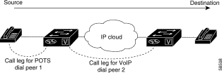
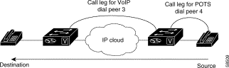
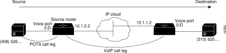
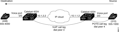
As shown in Figure 6-3 and Figure 6-4, a call leg is a discrete segment of a call connection that lies between two points in the connection. Each call leg corresponds to a dial peer. An end-to-end call consists of four call legs, two from the perspective of the source Catalyst 4224 (Figure 6-3) and two from the perspective of the destination Catalyst 4224 (Figure 6-4). Attributes applied to a call leg include QoS, Coder-Decoder (codec), voice activity detection (VAD), and fax rate.
There are two types of dial peers with each voice implementation:
Dial peers are used for both inbound and outbound call legs. The terms inbound and outbound are defined from the router perspective. An inbound call leg means that an incoming call comes to the router. An outbound call leg means that an outgoing call is placed from the router.
For inbound call legs, a dial peer might be associated with the calling number or the voice-port number. Outbound call legs always have an associated dial peer. The destination pattern is used to identify the outbound dial peer. The call is associated with the outbound dial peer at setup time.
A POTS dial peer associates a telephone number with a particular voice port so that incoming calls for that telephone number can be received and outgoing calls can be placed. VoIP dial peers point to specific devices (by associating destination telephone numbers with a specific IP address) so that incoming calls can be received and outgoing calls can be placed. To establish VoIP connections, you need both POTS and VoIP dial peers.
Establishing communication using VoIP is similar to configuring an IP static route; you are establishing a specific voice connection between two defined endpoints. As shown in Figure 6-5, the POTS dial peer establishes the source (via the originating telephone number or voice port) of the call. The VoIP dial peer establishes the destination by associating the destination telephone number with a specific IP address.
To configure call connectivity between the source and the destination as illustrated in Figure 6-5, enter the following commands on Catalyst 4224 10.1.2.2:
Figure 6-6 shows how to complete the end-to-end call between dial peer 1 and dial peer 4.
To complete the end-to-end call between dial peer 1 and dial peer 4, as illustrated in Figure 6-6, enter the following commands on Catalyst 4224 10.1.1.2:
Each dial peer needs to be identified by its unique data before you can configure dial peers in VoIP. Do this is by creating a dial peer configuration table.
Using the example in Figure 6-2, Router 1, with an IP address of 10.1.1.1, connects a small sales branch office to the main office through Router 2. There are three telephones in the sales branch office that need to be established as dial peers. Router 2, with an IP address of 10.1.1.2, is the primary gateway to the main office. There are four devices that need to be established as dial peers in the main office, and all are basic telephones connected to the PBX. Figure 6-2 shows a diagram of this small voice network, and Table 6-2 shows the dial peer configuration table for the example in the figure.
Table 6-2 Dial Peer Example Configuration Table
| Router | Dial Peer Tag | Commands | ||||
|---|---|---|---|---|---|---|
| Destination- Pattern | Type | Session Target | codec | QoS | ||
POTS dial peers enable incoming calls to be received by a particular telephony device. To configure a POTS dial peer, you need to uniquely identify the dial peer (by assigning it a unique tag number), define its telephone number(s), and associate it with a voice port through which calls are established. Under most circumstances, the default values for the remaining dial peer configuration commands are sufficient to establish connections.
To enter the dial peer configuration mode (and select POTS as the method of voice-related encapsulation), use the dial-peer voice number pots global configuration command. The number value is a tag that uniquely identifies the dial peer. (This number has local significance only.)
To configure the identified POTS dial peer, use the destination-pattern string dial peer configuration command. The string value is the destination telephone number associated with this POTS dial peer.
When a router receives a voice call, the router selects an outbound dial peer by comparing the called number with the number configured as the destination pattern for the POTS dial peer. The router then removes the left-justified numbers corresponding to the destination pattern that matches the called number. If you have configured a prefix, the prefix is put in front of the remaining numbers, creating a dial string, which the router then dials. If all numbers in the destination pattern are removed, the user receives a dial tone.
For example, suppose there is a voice call with the E.164 called number of 1-310-767-2222. If you configure a destination-pattern of 1310767 and a prefix of 9, the router removes 1310767 from the E.164 telephone number, leaving the extension number of 2222. It will then create a prefix 9 at the front of the remaining numbers, so that the actual numbers dialed are 9,2222. The comma in this example means that the router will pause for one second between dialing the 9 and the 2 to allow for a secondary dial tone.
VoIP dial peers enable outgoing calls to be made from a particular telephony device. To configure a VoIP dial peer, you need to identify the dial peer (by assigning it a unique tag number), define its destination telephone number, and define its destination IP address. The default values for the remaining dial peer configuration commands are usually adequate to establish connections.
To enter the dial peer configuration mode (and select VoIP as the method of voice-related encapsulation), use the dial-peer voice number voip global configuration command. The number value of the dial-peer voice voip command is a tag that uniquely identifies the dial peer.
To configure the identified VoIP dial peer, use the following dial peer configuration commands:
| Task | Command | |
|---|---|---|
| Step 1 | Define the destination telephone number associated with this VoIP dial peer. |
|
| Step 2 |
For examples of how to configure dial peers, see "VoIP Configuration Examples."
You can check the validity of your dial peer configuration by performing the following tasks:
If you are having trouble connecting a call and you suspect the problem is associated with the dial-peer configuration, you can try to resolve the problem by performing the following tasks:
Routers provide only analog voice ports for its implementation of VoIP. The type of signaling associated with analog voice ports depends on the voice interface card (VIC) installed in the device.
Each VIC is specific to a particular signaling type; therefore, VICs determine the type of signaling for the voice ports. Voice-port commands define the characteristics associated with a particular voice-port signaling type.
The voice ports support three basic voice signaling types:
Under most circumstances, the default voice port values are adequate to configure FXS and FXO ports to transport voice data over your existing IP network. However, if you need to change the default configuration for these voice ports, use the commands outlined in Table 6-3, beginning in privileged EXEC mode:
Table 6-3 Commands to Configure FXS and FXO Voice Ports
You can check the validity of your voice port configuration by performing the following tasks:
If you are having trouble connecting a call and you suspect the problem is associated with the voice port configuration, you can try to resolve the problem by performing the following tasks:
In most cases, the default values for voice-port tuning commands are sufficient. Depending on the specifics of your particular network, you might need to adjust voice parameters involving timing, input gain, and output attenuation for FXS or FXO voice ports. Collectively, these commands are referred to as voice-port tuning commands.
If you need to change the default tuning configuration for FXS and FXO voice ports, use the commands outlined in Table 6-4, beginning in privileged EXEC mode:
Table 6-4 Commands to Fine Tune FXS and FXO Voice Ports
|
Note After you change any voice port setting, Cisco recommends that you cycle the port by using the shutdown and no shutdown commands. |
Unlike FXS and FXO voice ports, the default E&M voice-port parameters are not sufficient to enable voice and data transmission over your IP network. Because of the inherent complexities of PBX networks, E&M voice port values must match those specified by the particular PBX device to which it is connected.
To configure E&M voice ports, use the commands outlined in Table 6-5, beginning in privileged EXEC mode:
Table 6-5 Commands to Configure E&M Voice Ports
You can check the validity of your voice port configuration by performing the following tasks:
If you are having trouble connecting a call and you suspect the problem is associated with the voice port configuration, you can try to resolve the problem by performing the following tasks:
In most cases, the default values for voice port tuning commands are sufficient. Depending on the specifics of your particular network, you might need to adjust voice parameters involving timing, input gain, and output attenuation for E&M voice ports. Collectively, these commands are referred to as voice port tuning commands.
If you need to change the default tuning configuration for E&M voice ports, use the commands shown in Table 6-6, beginning in privileged EXEC mode:
Table 6-6 Commands to Fine Tune E&M Voice Ports
|
Note After you change any voice port setting, Cisco recommends that you cycle the port by using the shutdown and no shutdown commands. |
Depending on how you have configured your network interfaces, you might need to configure additional VoIP dial-peer parameters. This section describes the following topics:
Use the ip precedence command to give voice packets a higher priority than other IP data traffic. The ip precedence command should also be used if RSVP is not enabled and you would like to give voice packets a priority over other IP data traffic. IP precedence scales better than RSVP but provides no admission control.
To give real-time voice traffic precedence over other IP network traffic, use the following global configuration commands:
Table 6-7 Global Configuration Commands for Dial Peers
In IP precedence, the numbers 1 through 5 identify classes for IP flows, while the numbers 6 and 7 are used for network and backbone routing and updates.
For example, to ensure that voice traffic associated with VoIP dial peer 103 is given a higher priority than other IP network traffic, enter the following:
In this example, when an IP call leg is associated with VoIP dial peer 103, all packets transmitted to the IP network via this dial peer will have their precedence bits set to 5. If the networks receiving these packets have been configured to recognize precedence bits, the packets are given priority over packets with a lower configured precedence value.
RSVP must be enabled at each LAN or WAN interface across which voice packets will travel. After enabling RSVP, you must use the req-qos dial-peer configuration command to request an RSVP session and configure the QoS for each VoIP dial peer. Otherwise, no bandwidth is reserved for voice traffic.
For example, to configure controlled-load QoS for VoIP dial peer 108, enter the following global configuration commands:
In this example, every time a connection is made through VoIP dial peer 108, an RSVP reservation request is made between the local router, all intermediate routers in the path, and the final destination router.
|
Note Cisco recommends that you select controlled-load for the requested QoS. The controlled-load service uses admission (or capacity) control to ensure that preferential service is provided even when the bandwidth is overloaded. |
To generate Simple Network Management Protocol (SNMP), use the following commands beginning in global configuration mode:
Table 6-8 Configuration Commands to Generate SNMP
| Task | Command | |
|---|---|---|
| Step 1 | Enter the dial peer configuration mode to configure a VoIP dial peer. |
|
| Step 2 | Generate an SNMP event if the QoS for a dial peer drops below a specified level. |
|
Note RSVP reservations are only one-way. If you configure RSVP, the VoIP dial peers on either side of the connection must be configured for RSVP. |
Coder-decoder (codec) typically is used to transform analog signals into a digital bit stream and digital signals back into analog signals. The codec specifies the voice coder rate of speech for a dial peer. Voice activity detection (VAD) is used to disable the transmission of silence packets. codec and VAD values for a dial peer determine how much bandwidth the voice session uses.
To specify a voice coder rate for a selected VoIP dial peer, use the following commands, beginning in global configuration mode:
Table 6-9 Configuration Commands to Specify a Voice Coder Rate
| Task | Command | |
|---|---|---|
| Step 1 | Enter the dial peer configuration mode to configure a VoIP dial peer. |
|
| Step 2 |
The default for the codec command is g729r8, which is normally the most desirable setting. However, if you are operating on a high-bandwidth network and voice quality is of the highest importance, you should configure the codec command for g711alaw or ulaw. Using g711alaw results in better voice quality, but it also requires higher bandwidth usage for voice.
For example, to specify a codec rate of g711alaw for VoIP dial peer 108, enter the following:
|
Note Prior to Cisco IOS Release 12.0(5)T, g729r8 is implemented in the pre-IETF format; thereafter, it is implemented in the standard IETF format. When new images, such as Release 12.0(5)T or later, interoperate with older versions of VoIP (when the g729r8 codec was not compliant with the IETF standard), users can hear garbled voices and ringback on either side of the connection. To avoid this problem, configure the dial peers with the g729r8 pre-ietf argument. |
To disable the transmission of silence packets and enable VAD for a selected VoIP dial peer, use the following global configuration commands:
Table 6-10 Commands to Disable the Transmission of Silence Packets
| Task | Command | |
|---|---|---|
| Step 1 | Enter dial peer configuration mode to configure a VoIP dial peer. |
|
| Step 2 |
The vad command is enabled by default, which is normally the most desirable setting. If you are operating on a high-bandwidth network and voice quality is of the highest importance, you should disable VAD. Disabling VAD results in better voice quality, but it also requires higher bandwidth usage for voice.
For example, to enable VAD for VoIP dial peer 108, enter the following:
When you are configuring VoIP, you need to take certain factors into consideration so that it runs smoothly over Frame Relay. A public Frame Relay cloud provides no QoS guarantee. For real-time traffic to be transmitted in a timely manner, the data rate must not exceed the committed information rate (CIR), or packets might be dropped. In addition, Frame Relay traffic shaping and RSVP are mutually exclusive. This is particularly important to remember if multiple data-link connection identifiers (DLCIs) are carried on a single interface.
For Frame Relay links with slow output rates (less than or equal to 64 kbps), where data and voice are transmitted over the same permanent virtual circuit (PVC), Cisco recommends the following solutions:
In Cisco IOS Release 12.0 T, Frame Relay traffic shaping is not compatible with RSVP. Cisco suggests one of the following workarounds:
For Frame Relay, it is customary to configure a main interface and several subinterfaces with one subinterface per PVC. The following example configures a Frame Relay main interface and a subinterface so that voice and data traffic can be successfully transported:
In this configuration example, the main interface is configured as follows:
The subinterface is configured as follows:
|
Note When traffic bursts over the CIR, the output rate is held at the speed configured for the CIR. For example, traffic will not go beyond 32 kbps if CIR is set to 32 kbps. |
For more information about configuring Frame Relay for VoIP, refer to the "Configuring Frame Relay" section in the Wide-Area Networking Configuration Guide for Cisco IOS Release 12.0 T.
![]()
![]()
![]()
![]()
![]()
![]()
![]()
![]()
Posted: Sat Apr 5 04:02:29 PST 2003
All contents are Copyright © 1992--2002 Cisco Systems, Inc. All rights reserved.
Important Notices and Privacy Statement.