|
|

This section describes the Catalyst 4224 Access Gateway Switch ports and the cables and adapters used to connect the switch to other devices.
This section includes the following topics:
Table B-1 lists the console connector pinouts.
| Pin | Signal | Direction | Description |
|---|---|---|---|
1 | RTS | output | Request to send |
2 | DTR | output | Data terminal ready |
3 | TXD | output | Transmit data |
4 | Ground |
|
|
5 | Ground |
|
|
6 | RXD | input | Receive data |
7 | DSR | input | Data set ready |
8 | CTS | input | Clear to send |
Table B-2 lists the management port pinouts.
| Pin | Signal | Direction | Description |
|---|---|---|---|
1 | RXD+ | input | Receive data diff1 pair |
2 | RXD- | input | Receive data diff pair |
3 | TXD+ | output | Transmit data diff pair |
4 | Ground |
| Unused pair |
5 | Ground |
| Unused pair |
6 | TXD- | output | Transmit data diff pair |
7 |
|
| Unused pair |
8 |
|
| Unused pair |
| 1Differential. There exists a positive and negative copy of the signal with a set impedance. |
Table B-3 lists the port and pin numbers on the RJ-21 pinout for the eight-port FXS module connector.
| Port Number | Connector Pin Number | Signal |
|---|---|---|
0 | 0 | Ring |
1 | 1 | Ring |
2 | 2 | Ring |
3 | 3 | Ring |
4 | 4 | Ring |
5 | 5 | Ring |
6 | 6 | Ring |
7 | 7 | Ring |
8 - 15 | 8 - 15 | Not Used |
16 - 24 | 16 - 24 | GND |
This section contains the following topics:
The schematics of crossover and straight-through cables are shown in Figure B-1 and Figure B-2.


This section contains the following topics:
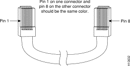
To identify a rollover cable, compare the two modular ends of the cable. Hold the cable ends side by side, with the tab at the back. The wire connected to the pin on the outside of the left plug should be the same color as the wire connected to the pin on the outside of the right plug (see Figure B-3).

Use the supplied thin, flat, RJ-45-to-RJ-45 rollover cable and RJ-45-to-DB-9 female DTE adapter to connect the console port to a PC running terminal-emulation software. Table B-4 lists the pinouts for the console port, the RJ-45-to-RJ-45 rollover cable, and the RJ-45-to-DB-9 female DTE adapter.
| Console Port (DTE) | RJ-45-to-RJ-45 Rollover Cable | RJ-45-to-DB-9 Terminal Adapter | Console Device | |
|---|---|---|---|---|
| Signal | RJ-45 Pin | RJ-45 Pin | DB-9 Pin | Signal |
RTS | 1 | 8 | 8 | CTS |
Not connected | 2 | 7 | 6 | DSR |
TxD | 3 | 6 | 2 | RxD |
GND | 4 | 5 | 5 | GND |
GND | 5 | 4 | 5 | GND |
RxD | 6 | 3 | 3 | TxD |
Not connected | 7 | 2 | 4 | DTR |
CTS | 8 | 1 | 7 | RTS |
Use the thin, flat, RJ-45-to-RJ-45 rollover cable and RJ-45-to-DB-25 female DTE adapter to connect the console port to a terminal. Table B-5 lists the pinouts for the console port, the RJ-45-to-RJ-45 rollover cable, and the RJ-45-to-DB-25 female DTE adapter.
 |
Note The RJ-45-to-DB-25 female DTE adapter is not supplied with the switch. You can order a kit (part number ACS-DSBUASYN=) containing this adapter from Cisco. |
| Console Port (DTE) | RJ-45-to-RJ-45 Rollover Cable | RJ-45-to-DB-25 Terminal Adapter | Console Device | |
|---|---|---|---|---|
| Signal | RJ-45 Pin | RJ-45 Pin | DB-25 Pin | Signal |
RTS | 1 | 8 | 5 | CTS |
DTF | 2 | 7 | 6 | DSR |
TxD | 3 | 6 | 3 | RxD |
GND | 4 | 5 | 7 | GND |
GND | 5 | 4 | 7 | GND |
RxD | 6 | 3 | 2 | TxD |
DTF | 7 | 2 | 20 | DTR |
CTS | 8 | 1 | 4 | |
![]()
![]()
![]()
![]()
![]()
![]()
![]()
![]()
Posted: Wed Jul 24 03:18:49 PDT 2002
All contents are Copyright © 1992--2002 Cisco Systems, Inc. All rights reserved.
Important Notices and Privacy Statement.