|
|

Table Of Contents
Installation and Configuration Note for the Catalyst 4500 Series Supervisor Engine II-Plus TS
Installing and Removing the Supervisor Engine
Installing the Supervisor Engine
Removing the Supervisor Engine
Attaching Module Interface Cables
Configuring Your Supervisor Engine
Standards Compliance Specifications
Obtaining Technical Assistance
Cisco Technical Support Website
Definitions of Service Request Severity
Obtaining Additional Publications and Information
Installation and Configuration Note for the Catalyst 4500 Series Supervisor Engine II-Plus TS
Product Numbers: WS-X4013+TS = Catalyst 4500 Series Supervisor Engine II-Plus TS
This publication describes how to install and verify the operation of the Catalyst 4500 series switch Supervisor Engine II-Plus TS. Refer to the software configuration guide for your switch to obtain configuration information for the supervisor engines and switching modules.
Contents
This document contains these sections:
•
Supervisor Engine II-Plus TS
•
•
•
•
•
•
Safety Overview
Throughout this publication, safety warnings appear in procedures that may harm you if performed incorrectly. A warning symbol precedes each warning statement.
Supervisor Engine II-Plus TS
This section describes the Catalyst 4500 series Supervisor Engine II-Plus TS (WS-X4013+ TS). This supervisor engine provides data path and data control for all network interfaces, and also provides 12 10/100/1000BASE-T IEEE 802.3af compliant Power over Ethernet (PoE) ports and 8 1000BASE-X SFP ports. A PoE-capable power supply is not needed to use PoE devices connected to the front panel ports on the Catalyst 4500 series Supervisor Engine II-Plus TS. A PoE-capable power supply would be needed to use PoE devices connected to modules in slot 2 and slot 3.
The Catalyst 4500 series Supervisor Engine II-Plus TS is only used in Catalyst 4503 switches. Install the Catalyst 4500 series Supervisor Engine II-Plus TS in slot 1.
The supervisor engine is hot swappable, but packets are not forwarded when the supervisor engine has been removed. When a supervisor engine is reinserted, the system reboots.
The Catalyst 4500 series Supervisor Engine II-Plus TS provides:
•
•
•
•
•
•
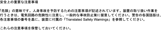
Figure 1 Catalyst 4500 Series Supervisor Engine II-Plus TS (WS-X4013+TS)
The supervisor engine includes interfaces for SNMP, console, and Telnet and provides management functions such as environmental status monitoring.
The following sections describe the LEDs, connectors, and switches on the Catalyst 4500 series Supervisor Engine II-Plus TS:
•
LEDs
Table 1 describes the LEDs on the supervisor engine front panel .
SFP Ports
The Gigabit Ethernet SFP ports operate in full-duplex mode only. These ports use the 1000BASE-SX, 1000BASE-LX, Cisco Coarse Wave Division Multiplexing (CWDM ) SFPs, 1000BASE-T SFP, and 1000BASE-ZX SFP. SFP connectors vary with interface type and may use multimode fiber (MMF), single-mode fiber (SMF) cable, or copper Ethernet cables. For further information on SFPs, see the "SFP Guidelines" section.
10/100/1000 Ports
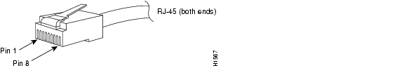
The 10/100/1000 ports operate in full-duplex mode or in half-duplex mode. These ports use RJ-45 connectors.
Ethernet Management Port
The Ethernet management port is used (in ROMMON mode only) to recover a switch software image that has been corrupted or destroyed. This port is not active while the switch is operating normally.
Console Port
The Catalyst 4500 series Supervisor Engine II-Plus TS console port has an EIA/TIA-232 RJ-45 connector. The console port allows you to perform the following functions:
•
•
•
Note
RESET Button
The RESET button is used to restart the switch.
Note
Flash Port
The Flash port accepts a Type 1 compact Flash card. You can use it for file transfer tasks such as loading a new software image. The Flash card is optional and can be obtained from Cisco resellers or directly from Cisco.
For more information, refer to Using the Compact Flash on the Catalyst 4000 Family Supervisor Engine III and IV at the following URL:
http://www.cisco.com/univercd/cc/td/doc/product/lan/cat4000/inst_nts/ol_2058.htm
Port Cabling Specifications
This section provides port cabling specifications.
The length of your networks and the distances between connections depend on the type of signal, the signal speed, and the transmission medium (the type of cabling used to transmit the signals). The distance and rate limits in this document are the IEEE-recommended maximum speeds and distances for signaling. Table 2 shows the transmission speed versus the distance.
Table 2 EIA/TIA-232 Transmission Speed in Contrast with Distance
2400
200
60
4800
100
30
9600
50
15
19,200
25
7.6
38,400
12
3.7
56,000
8.6
2.6
Maximum Cable Distances
Table 3 shows the maximum cable distances for transceiver speed and cable type.
Table 4 provides cabling specifications for the SFPs that you install in the SFP port modules.
Installing and Removing the Supervisor Engine
Warning
All Catalyst 4500 series switches support hot swapping, which lets you install, remove, replace, and rearrange supervisor engines and switching modules without powering off the system. When the system detects that a switching module has been installed or removed, it runs diagnostic and discovery routines automatically, acknowledges the presence or absence of the module, and resumes system operation with no operator intervention.
This section contains the following subsections:
•
•
Required Tools
You will need these tools to install a supervisor engine in a Catalyst 4500 series switch:
•
•
•
•
Note
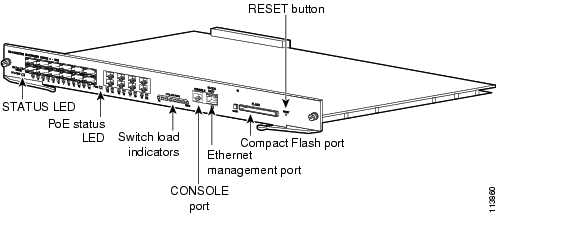
Installing the Supervisor Engine
The Catalyst 4500 series Supervisor Engine II-Plus TS is only used in Catalyst 4503 switches. Install the Catalyst 4500 series Supervisor Engine II-Plus TS in slot 1.
Warning
Caution
To install a supervisor engine in a Catalyst 4503 switch, follow this procedure:
Step 1
Step 2
Step 3
Step 4
Step 5
Step 6
Figure 2 Installing the Supervisor Engine in the Chassis
Step 7
Step 8
Step 9
Caution
Step 10
To check the status of the module, perform these steps:
Step 1
Step 2
Step 3
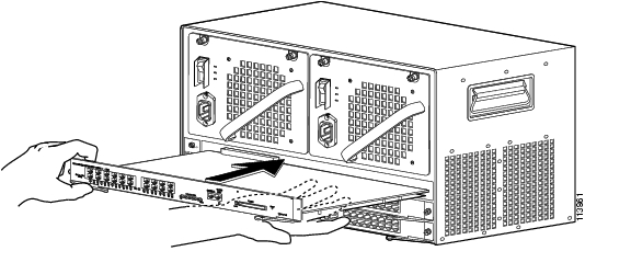
Removing the Supervisor Engine
Warning
Warning
Caution
To remove a supervisor engine from a Catalyst 4500 series switch, perform these steps:
Step 1
Step 2
Figure 3 Captive Installation Screws and Ejector Levers
Step 3
Step 4
Step 5
Step 6
Warning
Step 7
Warning
Attaching Module Interface Cables
Figure 4 shows the connector types used to attach interface cables to the supervisor engine.
Figure 4 RJ-45 Connector
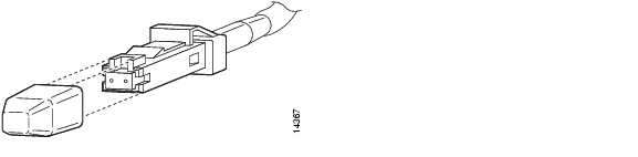
Figure 5 MT-RJ Connector
Note
Warning
Warning
Warning
Configuring Your Supervisor Engine
For information and commands to configure your supervisor engine, refer to the Software Configuration Guide for your switch.
SFP Guidelines
SFP modules are hot-pluggable and field-replaceable, and you can insert them into the eight SFP module slots on the front panel of the Supervisor Engine II+TS. You can use the SFP modules for connections to other network devices.
You can use any combination of supported SFP modules. Use only Cisco SFP modules on your Cisco device. Each SFP module has an internal serial EEPROM that is encoded with security information. This encoding provides a way for Cisco to identify and validate that the SFP module meets the requirements for the device.
The following SFP media types are supported:
•
•
•
•
•
Cisco 1000BASE-LX/LH interfaces fully comply with the IEEE 802.3z 1000BASE-LX standard. However, their higher optical quality allows them to reach 6.2 miles (10 km) over SMF cable instead of the 3.1 miles (5 km) specified in the standard.
If an LX/LH SFP designed for operation on an SMF cable is directly coupled to an MMF cable, an effect known as Differential Mode Delay (DMD) might occur. See the Catalyst 4500 Series Module Installation Guide for more information.
This section describes the following topics:
Fiber-Optic SFP Modules
Some fiber-optic SFP modules use LC-type connectors, as shown in Figure 6.
Caution
Figure 6 LC Fiber-Optic SFP Module
LC SFPs provide duplex single-mode and multimode connections in supported devices. Table 4 lists the cable specifications for fiber-optic SFP module ports.
Table 4 Fiber-Optic SFP Module Port Cabling Specifications
1000BASE-SX
850
MMF
62.5
62.5
50.0
50.0160
200
400
500722 feet (220 m)
902 feet (275 m)
1640 feet (500 m)
1804 feet (550 m)1000BASE-LX/LH
1300
MMF1
SMF62.5
50.0
50.0
9/10500
400
500
—1804 feet (550 m)
1804 feet (550 m)
1804 feet (550 m)
32,810 feet (10 km)1000BASE-ZX
1550
SMF
9/10
—
43.4 to 62 miles (70 to 100 km)2
1 A mode-conditioning patch cord is required. Using an ordinary patch cord with MMF, 1000BASE-LX/LH SFP modules, and a short link distance can cause transceiver saturation, resulting in an elevated bit error rate (BER). When using the LX/LH SFP module with 62.5-micron diameter MMF, you must also install a mode-conditioning patch cord between the SFP module and the MMF cable on both the sending and receiving ends of the link. The mode-conditioning patch cord is required for link distances greater than 984 feet (300 m).
2 1000BASE-ZX SFP modules can reach up to 62 miles (100 km) by using dispersion-shifted SMF or low-attenuation SMF; the distance depends on the fiber quality, the number of splices, and the connectors.
Note
When the fiber-optic cable span is less than 15.43 miles (25 km), you should insert a 5-decibel (dB) or 10-dB inline optical attenuator between the fiber-optic cable plant and the receiving port on the 1000BASE-ZX SFP module at each end of the link.Fiber-optic SFP modules also use MT-RJ connectors, as shown in Figure 7.
Figure 7 MT-RJ Fiber-Optic SFP Module
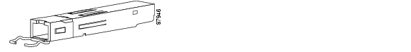
1000BASE-T SFP Modules
Copper 1000BASE-T SFP modules use RJ-45 connectors, as shown in Figure 8.
Figure 8 1000BASE-T Copper SFP Module
1000BASE-T copper SFP modules used with the Catalyst 4500 series Supervisor Engine II-Plus TS operate only in 1000BASE-T mode, or at 1000 Mbps. Copper 1000BASE-T SFP modules use standard four twisted-pair, Category 5 cable at lengths up to 328.08 feet (100 meters).
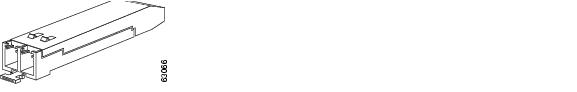
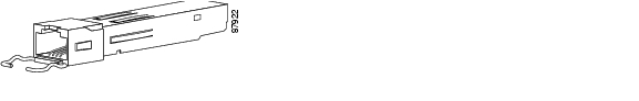
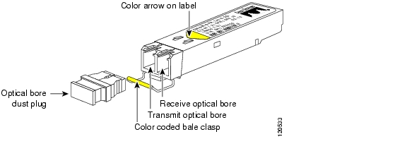
CWDM SFPs
You can connect the CWDM SFPs to CWDM passive optical system optical add/drop multiplexer (OADM) or multiplexer/demultiplexer plug-in modules using single-mode fiber-optic cables with standard SC connectors. Figure 9 shows a CWDM SFP with the optical port dust plug removed. Figure 10 shows an SC-type connector.
Figure 9 CWDM SFP Module (Yellow-Coded CWDM-SFP-1550= Shown)
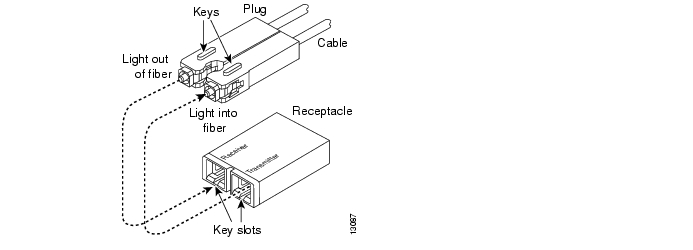
Figure 10 SC-Type Fiber-Optic Connector
CWDM SFPs come in eight wavelengths that range from 1470 nm to 1610 nm. Color markings on the devices identify the wavelength to which the Gigabit Ethernet channel is mapped. Table 5 lists the CWDM SFPs with their wavelengths and color codes.
Standards Compliance Specifications
When installed in a system, the Catalyst 4500 series modules comply with the standards listed in Table 6.
Table 6 Standards Compliance Specifications
CE1 Marking
UL2 60950, CSA3 -C22.2 No. 60950, EN4 60950, IEC5 60950, TS0016 ,
AS/NZS7 3260FCC9 Part 15, Class A (CFR10 47) (USA), ICES11 -003 Class A (Canada), EN 55022 Class A (Europe), CISPR2212 Class A (International), AS/NZS 3548 Class A (Australia), and VCCI13 Class A (Japan) with UTP14
1 CE = European Compliance
2 UL = Underwriters Laboratory
3 CSA = Canadian Standards Association
4 EN = European Norm
5 IEC = International Electrotechnical Commission
6 TS = technical specifications
7 AS/NZS = Australia Standards/New Zealand Standards
8 EMC = electromagnetic compatibility
9 FCC = U.S. Federal Communications Commission
10 CFR = Code of Federal Regulations
11 ICES = Interference-Causing Equipment Standard
12 CISPR = Comite International Special des Perturbation Radioelectriques
13 VCCI = Voluntary Control Council for Information Technology Equipment
14 UTP = unshielded twisted-pair
The Catalyst 4500 series modules have been found to comply with the limits for a Class A digital device per FCC (CFR 47) Part 15, ICES 003, EN55022, CISPR22, AS/NZS 3548, and VCCI with UTP cables, and complies with the limits for a Class B digital device per EN55022, CISPR22, AS/NZS 3548, and VCCI with shielded FTP cables.
Related Documentation
For more detailed installation and configuration information, refer to the following:
•
•
•
•
•
•
•
•
•
•
•
Obtaining Documentation
Cisco documentation and additional literature are available on Cisco.com. Cisco also provides several ways to obtain technical assistance and other technical resources. These sections explain how to obtain technical information from Cisco Systems.
Cisco.com
You can access the most current Cisco documentation at this URL:
http://www.cisco.com/univercd/home/home.htm
You can access the Cisco website at this URL:
You can access international Cisco websites at this URL:
http://www.cisco.com/public/countries_languages.shtml
Ordering Documentation
You can find instructions for ordering documentation at this URL:
http://www.cisco.com/univercd/cc/td/doc/es_inpck/pdi.htm
You can order Cisco documentation in these ways:
•
http://www.cisco.com/en/US/partner/ordering/index.shtml
•
Documentation Feedback
You can send comments about technical documentation to bug-doc@cisco.com.
You can submit comments by using the response card (if present) behind the front cover of your document or by writing to the following address:
Cisco Systems
Attn: Customer Document Ordering
170 West Tasman Drive
San Jose, CA 95134-9883We appreciate your comments.
Obtaining Technical Assistance
For all customers, partners, resellers, and distributors who hold valid Cisco service contracts, Cisco Technical Support provides 24-hour-a-day, award-winning technical assistance. The Cisco Technical Support Website on Cisco.com features extensive online support resources. In addition, Cisco Technical Assistance Center (TAC) engineers provide telephone support. If you do not hold a valid Cisco service contract, contact your reseller.
Cisco Technical Support Website
The Cisco Technical Support Website provides online documents and tools for troubleshooting and resolving technical issues with Cisco products and technologies. The website is available 24 hours a day, 365 days a year at this URL:
http://www.cisco.com/techsupport
Access to all tools on the Cisco Technical Support Website requires a Cisco.com user ID and password. If you have a valid service contract but do not have a user ID or password, you can register at this URL:
http://tools.cisco.com/RPF/register/register.do
Submitting a Service Request
Using the online TAC Service Request Tool is the fastest way to open S3 and S4 service requests. (S3 and S4 service requests are those in which your network is minimally impaired or for which you require product information.) After you describe your situation, the TAC Service Request Tool automatically provides recommended solutions. If your issue is not resolved using the recommended resources, your service request will be assigned to a Cisco TAC engineer. The TAC Service Request Tool is located at this URL:
http://www.cisco.com/techsupport/servicerequest
For S1 or S2 service requests or if you do not have Internet access, contact the Cisco TAC by telephone. (S1 or S2 service requests are those in which your production network is down or severely degraded.) Cisco TAC engineers are assigned immediately to S1 and S2 service requests to help keep your business operations running smoothly.
To open a service request by telephone, use one of the following numbers:
Asia-Pacific: +61 2 8446 7411 (Australia: 1 800 805 227)
EMEA: +32 2 704 55 55
USA: 1 800 553 2447For a complete list of Cisco TAC contacts, go to this URL:
http://www.cisco.com/techsupport/contacts
Definitions of Service Request Severity
To ensure that all service requests are reported in a standard format, Cisco has established severity definitions.
Severity 1 (S1)—Your network is "down," or there is a critical impact to your business operations. You and Cisco will commit all necessary resources around the clock to resolve the situation.
Severity 2 (S2)—Operation of an existing network is severely degraded, or significant aspects of your business operation are negatively affected by inadequate performance of Cisco products. You and Cisco will commit full-time resources during normal business hours to resolve the situation.
Severity 3 (S3)—Operational performance of your network is impaired, but most business operations remain functional. You and Cisco will commit resources during normal business hours to restore service to satisfactory levels.
Severity 4 (S4)—You require information or assistance with Cisco product capabilities, installation, or configuration. There is little or no effect on your business operations.
Obtaining Additional Publications and Information
Information about Cisco products, technologies, and network solutions is available from various online and printed sources.
•
http://www.cisco.com/go/marketplace/
•
http://cisco.com/univercd/cc/td/doc/pcat/
•
•
•
http://www.cisco.com/go/iqmagazine
•
•
http://www.cisco.com/en/US/learning/index.html
![]()
![]()
![]()
![]()
![]()
![]()
![]()
![]()
Posted: Wed Nov 24 11:42:26 PST 2004
All contents are Copyright © 1992--2004 Cisco Systems, Inc. All rights reserved.
Important Notices and Privacy Statement.