|
|

This chapter describes how to install the Cisco Catalyst 4000 Access Gateway Module (AGM) in a Catalyst 4000 family switch chassis.
This chapter contains these major sections:
 |
Warning Before you install, operate, or service the system, read the Site Preparation and Safety Guide. This guide contains important safety information you should know before working with the system. |
You need these tools to install the AGM and the supported interface modules:
|
Warning Only trained and qualified personnel should be allowed to install, replace, or service this equipment. |
 |
Caution Before you handle switching modules, read the "Preventing Electrostatic Discharge Damage" section. |
You also need an appropriate connecting cable to install and connect your interface module(s). The cable type required for each module is described in the section for that module.
These items are optional:
Electrostatic discharge (ESD) damage, which can occur when electronic cards or components are improperly handled, results in complete or intermittent failures. Port adapters and processor modules comprise printed circuit boards that are fixed in metal carriers. Electromagnetic interference (EMI) shielding and connectors are integral components of the carrier. Although the metal carrier helps to protect the board from ESD, use a preventive antistatic strap during handling.
Following are guidelines for preventing ESD damage:
|
Caution Never attempt to remove the printed circuit board from the metal carrier. |
|
Caution To prevent ESD damage, handle switching modules by the carrier edges only. Whenever you handle switching modules, you should use a wrist strap or other grounding device. |
To install the AGM, you might need to remove a switching module from a Catalyst 4000 family switch. If so, perform these steps:
Step 1 Disconnect any network interface cables attached to the ports on the switching module that you intend to remove.
Step 2 Loosen the captive installation screws, as shown in Figure 2-1. This figure displays the AGM, but the instructions apply to all the switch modules.

Step 3 Grasp the left and right ejector levers and simultaneously pivot the levers outward to release the switching module from the backplane connector.
Figure 2-1 shows a close-up of the right ejector lever.
Step 4 Grasp the switching module front panel with one hand and place your other hand under the carrier to support and guide it out of the slot.
Do not touch the printed circuit boards or connector pins.
Step 5 Carefully pull the switching module straight out of the slot, keeping your other hand under the carrier to guide it.
Step 6 Place the switching module on an antistatic mat or antistatic foam, or immediately install it in another slot.
Step 7 If the slot will remain empty, install a switching module filler plate (part number 800-00292-01).
All Catalyst 4000 family switching modules are installed in horizontal chassis slots that are numbered from top to bottom.
You can remove and install the AGM without powering down the switch. This feature is known as hot swapping.
|
Caution To prevent ESD damage, handle the AGM by the carrier edges only. Moreover, you should use a wrist strap or other grounding device to prevent ESD damage. |
To install the AGM, perform these steps:
Step 1 Choose a slot for the new AGM.
 |
Note The AGM can be inserted into slots 2 or 3 in the Catalyst 4003 switch and slots 2 through 6 in the Catalyst 4006 switch. In the Catalyst 4003 and Catalyst 4006 switches, slot 1 is reserved for the supervisor engine. |
Ensure that you have enough clearance to accommodate any interface equipment that you will connect directly to the AGM ports. If possible, place AGMs between empty slots that contain only switching module filler plates.
Step 2 Loosen the captive installation screws securing the switching module filler plate (or the existing switching module) to the desired slot.
Step 3 Remove the switching module filler plate (or the existing switching module). Save the switching module filler plate for future use.
|
Note If you are removing an existing switching module, refer to the "Removing Catalyst 4000 Switching Modules (optional)" section. |
Step 4 To install the new AGM, hold the switching module front panel with one hand, and place your other hand under the carrier to support the module, as shown in Figure 2-2. Do not touch the printed circuit boards or connector pins.
Step 5 Align the edges of the AGM carrier with the slot guides on the sides of the switch chassis, as shown in Figure 2-2.

Step 6 Pivot the two module ejector levers out away from the faceplate.
Step 7 Carefully slide the AGM into the slot until the notches on both ejector levers engage the chassis sides.
Step 8 Using the thumb and forefinger of each hand, simultaneously pivot in both ejector levers to fully seat the AGM in the backplane connector.
|
Caution Always use the ejector levers when installing or removing the AGM. A module that is partially seated in the backplane will cause the system to halt and reset. Ensure that the ejectors are locked when the module is in the slot. |
Step 9 Tighten the captive installation screws on each end of the AGM faceplate.
Although you can hot swap the AGM without powering down the switch, you cannot hot swap the interface modules.
|
Caution Hot swapping a VIC, WIC, or VWIC from the AGM could damage the module. Their installation requires removing the AGM from the chassis. |
When you remove or insert the AGM while the switch is powered on and operating, the system does the following:
1. Scans the backplane for configuration changes.
2. Initializes all newly inserted AGM, notes any removed modules, and places them in the administratively shutdown state.
3. Places any previously configured interfaces on the AGM back to the state they were in when they were removed. Any newly inserted interfaces are put in the administratively shutdown state, as if they were present (but not configured) at boot time.
The system runs diagnostic tests on any new interfaces.
|
Caution To avoid erroneous failure messages, allow at least 2 minutes for the system to reinitialize, and note the current configuration of all interfaces before you remove or insert another AGM. |
When you hot swap an AGM, the system displays status messages on the console. The following example shows the messages logged by the system when a gateway module is removed from slot 3:
Console> (enable)
1999 Sep 09 12:23:26 %SYS-5-MOD_REMOVE:Module 3 has been removed
Console> (enable)
1999 Sep 09 12:23:44 %SYS-5-MOD_INSERT:Module 3 has been inserted
Console> (enable)
1999 Sep 09 12:23:47 %SYS-5-MOD_OK:Module 3 is online
Console> (enable)
If you use the show mod command to query the module before reinstalling a module to replace the removed one, the system responds, "Module 3 is not installed." When the module is reinserted, the system recognizes the module as ready again.
|
Note Running the show mod command can take a few minutes. |
The AGM can take up to two minutes to boot and it does not appear on the supervisor engine console until IOS is operating. The latter might take up to 10 minutes.
To check the status of the module, perform these steps:
Step 1 Ensure that the LED labeled STATUS is green (indicating the module is operational).
Step 2 When the switch is online, enter the show module command. Verify that the system acknowledges the new module and that the status of the module is good.
Step 3 If the module is not operational, reseat it. If the module is still not operational, contact your customer service representative.
The AGM has four slots reserved for WAN interface modules (WICs), voice interface modules (VICs), and T1/E1 multiflex voice/WAN interface modules (VWICs). You can install any combination of VICs, WICs, and VWICs in slots 1 and 2, but slot 3 accepts only VICs and VWICs. Slot 4 is filled with the high-density analog module when you first receive the switch.
|
Note VICs, WICs, and VWICs do not support online insertion and removal (hot swapping). |
|
Caution Before inserting a VIC, WIC, or VWIC into the AGM, you must turn off the electrical power by either powering off the switch or unplugging the AGM from the chassis and disconnecting the network cables. |
|
Warning Do not work on the system or connect or disconnect cables during periods of lightning activity. |
|
Warning This equipment is to be installed and maintained by service personnel only as defined by AS/NZS 3260 Clause 1.2.14.3 Service Personnel. |
|
Warning Incorrect connection of this or connected equipment to a general purpose outlet could result in a hazardous situation. |
|
Warning The telecommunications lines must be disconnected 1) before unplugging the main power connector and/or 2) while the housing is open. |
|
Warning Hazardous network voltages are present in WAN ports regardless of whether power to the unit is OFF or ON. To avoid electric shock, use caution when working near WAN ports. When detaching cables, detach the end away from the unit first. |
|
Warning To avoid electric shock, do not connect safety extra-low voltage (SELV) circuits to telephone-network voltage (TNV) circuits. LAN ports contain SELV circuits, and WAN ports contain TNV circuits. Some LAN and WAN ports both use RJ-45 connectors. Use caution when connecting cables. |
|
Warning Network hazardous voltages are present in the BRI, fractional T1/T1, and Switched 56 cables. If you detach the cable, detach the end away from the router first to avoid possible electric shock. Network hazardous voltages are also present in the area of the BRI (RJ-45), fractional T1/T1 (RJ-48C), and Switched 56 (RJ-11 or RJ-48S) ports, regardless of whether power is off or on. |
|
Warning To reduce the risk of fire, use only No. 26 AWG or larger telecommunication line cord. |
To install a VIC/WIC, perform these steps:
Step 1 If the switch is powered on, remove the AGM from the chassis or power off the chassis.
Step 2 Remove all network interface cables, including telephone cables, from the front panel.
|
Note To channel ESD voltages to ground, do not unplug the power cable. |
Step 3 Use either a number 2 Phillips screwdriver or a small flat-blade screwdriver to loosen the screws of the blank faceplate and remove the faceplate from the interface slot where you plan to install the module. Save the faceplate for future use.
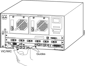
Step 4 Align the module with the cable guides in the interface slot and slide the module gently into the slot. (See Figure 2-3.)
|
Warning Blank faceplates and cover panels serve three important functions: they prevent exposure to hazardous voltages and currents inside the chassis; they contain EMI that might disrupt other equipment; and they direct the flow of cooling air through the chassis. Do not operate the system unless all modules, faceplates, front covers, and rear covers are in place. |
Step 5 Push the module into place until you feel its edge connector mate securely with the connector in the interface slot.
Step 6 Place the captive mounting screws on the card into the holes in the AGM faceplate and fasten them using a Phillips or flat-blade screwdriver.
Step 7 Reinsert the AGM, restore the power, reinstall the network interface cables, and turn on power to the switch.
These sections describe how to connect the supported VWICs, WICs, and VICs:
This section describes the procedures for connecting the following WAN interface modules:
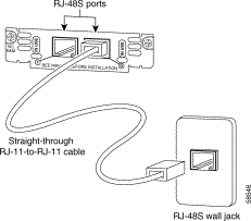
This section describes how to connect and verify the status of the 1-port 56/64-kbps Data Service Unit/Channel Service Unit (DSU/CSU) interface modules (WIC-1DSU-56K).
Use a straight-through RJ-48S-to-RJ-48S or the straight-through RJ-48C-to-RJ-48C cable that shipped with the AGM.
To connect the 1-port 56/64-kbps DSU/CSU module, perform these steps:
Step 1 Power off the AGM.
Step 2 Connect one end of the cable to the 56/64-kbps port of the module, as shown in Figure 2-4.
Step 3 Connect the other end of the cable to the RJ-48S wall jack, as shown in Figure 2-4.

Step 4 Power on the AGM.
Step 5 Verify that the CD LED is green, indicating that the internal DSU/CSU is communicating with another DSU/CSU.
Table 2-1 describes the 56/64-kbps WAN interface module LEDs.
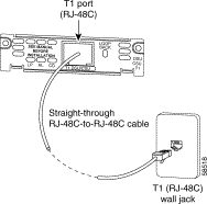
This section describes how to connect and verify the status of the 1-port T1/FT1 DSU/CSU interface module (WIC-1DSU-T1).
Use a straight-through RJ-48S-to-RJ-48S or the straight-through RJ-48C-to-RJ-48C cable that shipped with the AGM.
To connect the 1-port T1/FT1 module, perform these steps:
Step 1 Power off the AGM.
Step 2 Connect one end of the cable to the T1/FT1 port of the module, as shown in Figure 2-5.
Step 3 Connect the other end of the cable to the RJ-48S wall jack, as shown in Figure 2-5.
Step 4 Power on the AGM.
Step 5 Verify that the CD LED is green, indicating that the internal DSU/CSU in the module is communicating with another DSU/CSU.
Table 2-2 describes the T1/FT1 WAN interface module LEDs.
This section describes how to connect and verify the status of 2-port asynchronous/synchronous (A/S) serial modules (WIC-2A/S).
|
Note The AGM does not support asynchronous mode operation at this time. |
The 2-port A/S serial module has "smart" serial ports. The serial cable attached to one of the module's ports can determine the electrical interface type and mode (DTE or DCE).
Six types of serial cables (also called serial adapter cables or serial transition cables) are available from Cisco Systems for use with the 2-port A/S serial module:
All serial cables have a universal plug at the interface module end. The network end of each cable provides the physical connectors that are most commonly used for the interface. For example, the network end of the EIA/TIA-232 serial cable is a DB-25 connector, which is the most widely used EIA/TIA-232 connector.
All serial interface types, except EIA-530, are available in DTE or DCE mode: DTE with a plug connector at the network end and DCE with a receptacle at the network end. The V.35 assembly is available in either mode with either gender at the network end. The EIA/TIA-530 assembly is available in DTE only.
After you install the 2-port A/S serial module, use the appropriate serial cable to connect the serial port on the module to one of the following types of equipment (see Figure 2-6):
To connect the 2-port A/S serial module, perform these steps:
Step 1 Power off the AGM.
Step 2 Connect one end of the appropriate serial cable to a DB-60 port on the module, as shown in Figure 2-6.
Step 3 Connect the other end of the cable to the appropriate type of equipment, as shown in Figure 2-6.
Step 4 Power on the AGM.
Step 5 Verify that the CONN LED goes on, indicating that the serial port on the module detects the WAN serial connection.
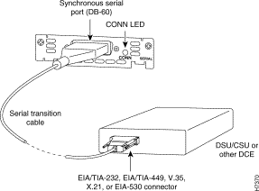
Table 2-3 describes the 2-port A/S serial interface module LED.
| LED | Description |
|---|---|
CONN | Green indicates that the serial port detects a WAN serial connection. |
This section describes how to connect and verify the status of the 1- and 2-port serial modules (WIC-1T and WIC-2T).
|
Note The AGM does not support asynchronous mode operation at this time. |
The 2-port A/S serial module has "smart" serial ports. The serial cable attached to one of the module's ports can determine the electrical interface type and mode (DTE or DCE).
Six types of serial cables (also called serial adapter cables or serial transition cables) are available from Cisco Systems for use with the 2-port A/S serial module:
All serial cables provide a universal plug at the interface module end. The network end of each cable provides the physical connectors that are most commonly used for the interface. For example, the network end of the EIA/TIA-232 serial cable is a DB-25 connector, which is the most widely used EIA/TIA-232 connector.
All serial interface types except EIA-530 are available in the following DTE or DCE mode: DTE with a plug connector at the network end and DCE with a receptacle at the network end. The V.35 assembly is available in either mode with either gender at the network end. The EIA/TIA-530 assembly is available in DTE only.
After you install the 2-port A/S serial module, use the appropriate serial cable to connect the serial port on the module to one of the following types of equipment (see Figure 2-7):
To connect either the 1- or 2-port serial module, perform these steps:
Step 1 Power of the AGM.
Step 2 Connect one end of the appropriate serial cable to a DB-60 port on the module, as shown in Figure 2-7.
Step 3 Connect the other end of the cable to the appropriate type of equipment, as shown in Figure 2-7.
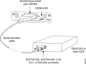
Step 4 Power on the AGM.
Step 5 Verify that the CONN LED goes on, indicating that the serial port on the module detects the WAN serial connection.
Table 2-4 describes the serial WAN interface module LED.
| LED | Description |
|---|---|
CONN | Green indicates that the serial port detects the WAN serial connection. |
This section describes how to connect the following voice interface modules:
This section describes how to connect and verify the status of the 2-port FXS voice interface module (VIC-2FXS or VIC-2FXS-EU).
The 2-port FXS voice interface module has two jumper headers (W3 and W4) that you can use to set loop-start or ground-start mode. One jumper configures each FXS port. The default setting is loop start. In the default setting, jumpers are placed over positions 2 and 3 of headers W3 and W4.
Most modern central office (CO) equipment, such as the DMS-100 and 5ESS switches, provides the calling party control (CPC) and Ring on Seize (ROS) features on loop-start lines. CPC provides faster disconnection, and ROS minimizes glare (collision of inbound and outbound calls on the same interface). If your CO does not provide these features on loop-start wires, you may want to configure the FXS module for ground-start operation instead by moving the jumpers to positions 1 and 2.
For proper operation, you must configure both jumpers identically. In most cases, the jumper setting should have little or no effect on operation.
|
Note Jumper settings apply only to VIC-2FXS. |
Use a standard RJ-11 modular telephone cable to connect the 2-port FXS module to the PSTN or PBX through a telephone jack.
To connect the 2-port FXS module, perform these steps:
Step 1 Power off the AGM.
Step 2 Connect one end of the cable to one of the RJ-11 ports of the module, as shown on Figure 2-8.
Step 3 Connect the other end of the cable to the RJ-11 wall jack, as shown on Figure 2-8.
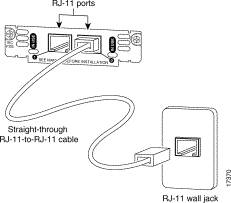
Step 4 Power on the AGM.
Step 5 verify the LED is green.
Table 2-5 describes the FXS voice interface module LED.
| LED | Description |
|---|---|
IN USE | Green indicates that an off-hook has been detected. Off indicates that an on-hook has been detected. |
The VIC-2FXS-EU voice interface module is intended for use in Europe. In countries where PSTNs do not use RJ-11 wall jacks, use a suitable adapter to convert the plug on an RJ-11 modular cable to the type of wall jack connector that is used in your country. These adapters are not sold by Cisco Systems but are available from other vendors.
|
Caution Connect only an FXS interface that is approved for use in your country to the PSTN. Otherwise, connect the FXS interface only to a PBX. |
This section describes how to connect and verify the status of an 8-port RJ21 FXS module (WS-U4604-8FXS).
This section describes the following topics:
Figure 2-9 shows examples of the RJ-21 telco connector for the RJ-21 port on the 8-port FXS module. The connectors are available in three cable-to-connector orientations: 90 degrees, 110 degrees, and 180 degrees.
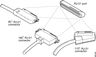
Because 90 degree RJ-21 connectors have only one screw, they require additional support to hold one side of the connector to the module. We supply a bracket and a velcro strap in the accessory kit (see Figure 2-10) for this purpose.
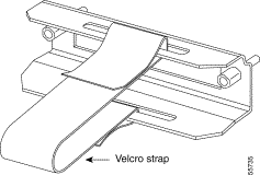
To attach the bracket to the 8-port FXS module, perform these steps:
Step 1 Remove the two screws from the 8-port FXS module front panel with a flat-blade screwdriver.
Step 2 Align the screws on the bracket with the holes on the 8-port FXS module, and then tighten them.
Step 3 Align the screw on the 90 degrees RJ-21 connector with the appropriate screw top on the bracket, and then tighten the screw.
Step 4 Attach the velcro strap as illustrated in Figure 2-11.
Use a standard RJ-21 Category 5 telco connector and cable to connect the 8-port FXS module jack to the breakout box.
To connect the 8-port RJ21 FXS module, perform these steps:
Step 1 Power off the AGM.
Step 2 Connect one end of the RJ-21 cable to a telco RJ-21, as shown on Figure 2-11.
Step 3 Connect the other end of the cable to the breakout box or patch panel, as shown on Figure 2-11.
Step 4 Power off the AGM.
Step 5 Verify that the HDA LED is green. This LED indicates that IOS is running.
|
Warning If the symbol of suitability with an overlaid cross appears above a port, you must not connect the port to a public network that follows the European Union standards. Connecting the port to this type of public network can cause severe injury or damage your router. |
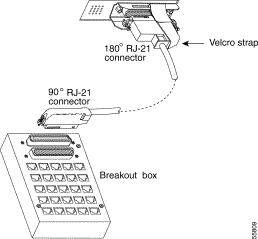
Table 2-6 describes the 8-port RJ21 FXS module link LED.
Figure 2-12 shows the pinout convention for the telco RJ-21 (tip and ring on 25 pairs). The top row is ring, the bottom row is tip. For the 8-port FXS module, only the eight pairs to the right are used. The middle set of eight pairs is shorted together but not to ground.
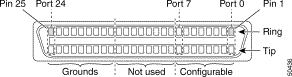
See Table C-3 in "Connector and Cable Specifications" for a mapping of the RJ-21 pinouts for the 8-port FXS module connector.
This section describes how to connect and verify the status of the 2-port FXO voice interface modules (VIC-2FXO, VIC-2FXO-M1, VIC-2FXO-EU, VIC-2FXO-M2, and VIC-2FXO-M3).
The 2-port FXO voice interface module includes two jumper headers (W3 and W4) that you can use to set loop-start or ground-start mode. One jumper configures each FXO port. The default setting is loop start. In the default setting, jumpers are placed over positions 2 and 3 of headers W3 and W4.
Updated modern CO equipment, such as the DMS-100 and 5ESS switches, provides the CPC and ROS features on loop-start lines. CPC provides faster disconnection, and ROS minimizes glare (collision of inbound and outbound calls on the same interface). If your CO does not provide these features on loop-start lines, you may want to configure the FXO module for ground-start operation instead by moving the jumpers to positions 1 and 2.
For proper operation, you must configure both jumpers identically. In most cases, the jumper setting should have little or no effect on operation.
|
Note This jumper setting does not apply to VIC-2FXO-EU. |
Use a standard RJ-11 modular telephone cable to connect the 2-port FXO module to the PSTN or PBX through a telephone jack. To connect the 2-port FXO module, perform these steps:
Step 1 Power off the AGM.
Step 2 Connect one end of the cable to one of the RJ-11 ports of the module, as shown in Figure 2-13.
Step 3 Connect the other end of the cable to the RJ-11 wall jack, as shown in Figure 2-13.
Step 4 Power on the AGM.
Step 5 verify the IN USE LED is green, indicating that the line is in use.
Table 2-7 describes the E/M voice interface module LED.
| LED | Description |
|---|---|
IN USE | Green indicates that the line is in use. |
The VIC-2FXO-EU voice interface module is intended for use in Europe. In countries where PSTNs do not use RJ-11 wall jacks, use a suitable adapter to convert the plug on an RJ-11 modular cable to the type of wall outlet connector that is used in your country. These adapters are not sold by Cisco Systems but are available from other vendors.
|
Caution Connect only an FXO interface that is approved for use in your country to the PSTN. Otherwise, connect the FXO interface only to a PBX. Connections from the PBX to the PSTN are permitted. |
This section describes how to connect and verify the status of the 2-port E/M voice interface module (VIC-2E/M).
Use a standard RJ-11 modular telephone cable to connect this interface to the PBX. Unlike the FXS and FXO modules, the E/M module requires an RJ48S connector. The pinout depends on the PBX type and connection.
To connect the 2-port E/M module, perform these steps:
Step 1 Power off the AGM.
Step 2 Connect one end of the RJ-11 cable to one of the RJ48S ports of the module, as shown in Figure 2-14.
Step 3 Connect the other end of the cable to the RJ48S wall jack, as shown in Figure 2-14.
Step 4 Power on the AGM.
Step 5 verify the IN USE LED is green, indicating that line is in use.
Table 2-8 describes the E/M voice interface module LED.
| LED | Description |
|---|---|
IN USE | Green indicates that the line is active. |
This section describes how to connect and verify the status of the 2-port ISDN BRI modules (VIC-2BRI-S/T-TE).
Use the straight through RJ-48C-to-RJ-48C cable that shipped with your AGM.
To connect the 2-port ISDN BRI module, perform these steps:
Step 1 Power off the AGM.
Step 2 Connect one end of the cable to one of the RJ-48C ports of the module, as shown in Figure 2-15.
Step 3 Connect the other end of the cable to one of the RJ-48C S/T ports on an NT1 device, as shown in Figure 2-15.
|
Caution To prevent damage to the switch, be sure to connect the cable to the BRI connector only. Do not connect the cable to any other RJ-48C connector. |
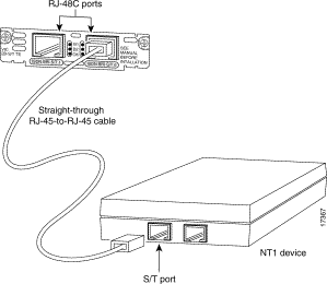
Step 4 Power on the AGM.
Step 5 Verify that the OK LED is green, indicating that the module is connected to an ISDN network.
Table 2-9 describes the ISDN BRI voice interface module LEDs.
This section describes how to connect the following interface modules:
This section describes how to connect and verify the status of the 1-port multiflex trunk interface modules (VWIC-1MFT-T1, VWIC-1MFT-E1, or VWIC-1MFT-G703).
Use the straight-through RJ-48C-to-RJ-48C cable that shipped with the AGM.
To connect the 1-port multiflex trunk interface module, perform these steps:
Step 1 Power off the AGM.
Step 2 Connect one end of the cable to the RJ-48C port of the module, as shown in Figure 2-16.
Step 3 Connect the other end of the cable to the RJ-48C wall jack at your site, as shown in Figure 2-16.
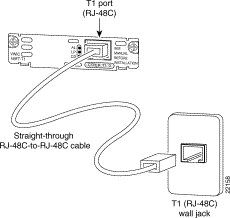
Step 4 Power on the AGM.
Step 5 Verify that the CD LED is green, indicating that the module's internal DSU/CSU is communicating with the DSU/CSU at the T1 or E1 service provider's CO.
Table 2-10 describes the 1-port multiflex trunk interface module LEDs.
This section describes how to connect and verify the status of the 2-port multiflex trunk interface modules (VWIC-2MFT-T1, VWIC-2MFT-E1, VWIC-2MFT-T1-DI, VWIC-2MFT-E1-DI, or VWIC-2MFT-G703).
Use the straight-through RJ-48C-to-RJ-48C cable that shipped with the AGM.
To connect the 2-port multiflex trunk interface module, perform these steps:
Step 1 Power off the AGM.
Step 2 Connect one end of the cable to one of the RJ-48C ports of the module, as shown in Figure 2-17.
Step 3 Connect the other end of the cable to the T1 or E1 (RJ-48C) wall jack at your site, as shown in Figure 2-17.
Step 4 Power on the AGM.
Step 5 Verify that the CD LED is green, indicating that the module's internal DSU/CSU is communicating with the DSU/CSU at the T1 or E1 service provider CO.
Table 2-11 describes the 2-port multiflex interface module LEDs.
If you have additional modules to install, proceed to the appropriate section in this document.
The console and 10/100 Mbps Ethernet management ports are located on the front panel of the AGM. (See Figure 2-1) The console and Ethernet management ports use an RJ-45 media-dependent interface crossed-over (MDIX) connector (see Figure 2-18). Table 2-12 lists the console port pinouts and Table 2-13 lists the 10/100 Mbps Ethernet management port pinouts.
|
Note The MDIX ports are crossed over internally. For an MDI-to-MDI or MDIX-to-MDIX connection, use a crossover cable. For an MDI-to-MDIX connection, use a straight-through cable, which allows the Tx pins to connect with the Rx pins. |

![]()
![]()
![]()
![]()
![]()
![]()
![]()
![]()
Posted: Thu Dec 19 10:07:01 PST 2002
All contents are Copyright © 1992--2002 Cisco Systems, Inc. All rights reserved.
Important Notices and Privacy Statement.
