|
|

The 2.1 software release includes the following feature enhancements:
Learn and Lock, also known as MAC Address Port Security, allows an Ethernet port in a Catalyst 3000 series switch to block input to an Ethernet or Fast Ethernet port when the MAC address of a station attempting to access the port is different from the MAC address learned on or configured for that port. When a Catalyst 3000 series switch receives a packet, the switch compares the source address of that packet to the secure source address learned by or configured for that port (see Step 5, in the following steps, for information on Static Address Learning). When a source MAC address, other than that learned by or configured for a port is detected, the port is disabled and an SNMP trap is sent.
To enable Learn and Lock at a specific port, perform the following steps:
Step 1 Access the main Configuration menu and select the heading Learn and Lock.
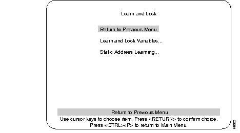
Step 2 Select the Learn and Lock Variables heading. Use this menu to enable or disable Learn and Lock (see the following Learn and Lock Variables menu screen).
Step 3 To change the variables in the Learn and Lock Variables menu, use the cursor keys to choose the item and press RETURN.
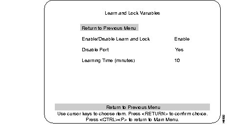
Step 4 When Learn and Lock is enabled port learning options can be configured from the Static Address Learning menu.
Step 5 Return to the Learn and Lock menu and select the heading Static Address Learning. In the following Static Address Learning menu example:
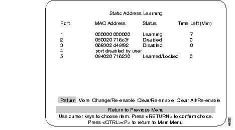
Step 6 From the Static Address Learning menu you can clear a learned address and restart address learning or statically enter an address and therefore specify the source MAC address the port is authorized to accept.
When spanning tree is enabled, the Port Fast feature reduces a port's transition time from blocking to forwarding. (For a detailed explanation of the features of spanning tree, see Chapter 7 in the Installation and Configuration Guide for the Catalyst 3000 series switches.)
When a port link is enabled, spanning tree will place the port in Blocking mode to prevent a loop from forming. If a loop does not form, spanning tree will change the Blocking mode to:
Forwarding allows traffic to enter and leave the port. The transition time from Blocking to Forwarding can average 30 seconds. Using Port Fast, as soon as the port's link is up, the port will go directly to Forwarding mode. If a loop should form after the port enters Forwarding mode, spanning tree changes the port's state from Forwarding to Blocking mode. Port Fast does not affect any other feature of spanning tree.
Use the following steps and menus to configure Port Fast:
Step 1 Using the console, access the Configuration menu and select the Spanning Tree menu.
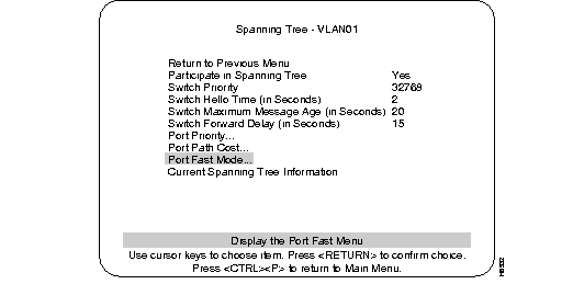
Step 2 At the Spanning Tree menu, select the Port Fast menu. The following menu is displayed:
Port Fast Mode menu: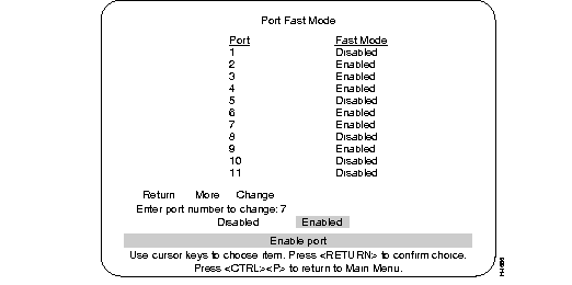
Step 3 Select a port.
Step 4 Select Disabled or Enabled
Observe the following restrictions when using Port Fast configuration:
ATM is a connection-oriented technology providing point-to-point and point-to-multicast circuit networking. Legacy LANs are connection-less and shared medium based technologies. ATM Forum has standardized LAN Emulation protocols to emulate a broadcast environment such as IEE802.3 Ethernet over an ATM network. Each emulated LAN consists of a set of LAN Emulation clients(LECs) and a single LAN Emulation service. The LAN Emulation service consists of LAN Emulation Configuration Server(LECS), a LAN Emulation Server(LES) and a Broadcast and Unknown Server(BUS). Communication among LECs and the LAN Emulation Service takes place over ATM virtual channel connections(VCCs). Each LEC establishes control direct VCCs to the LES and multicast VCCs to the BUS for emulating a LAN over an ATM network.
Using software release 2.1, a Catalyst 3000 series WS-X3006A ATM module can function as one of the following ATM configurations:
The following is a list of requirements necessary to run software release 2.1 on a Catalyst 3000 series switch:
The following sections describe configurations for ATM Client/Server functions. New ATM configuration menus referencing specific ATM configurations are displayed as they are referenced. Standard menus such as the Configuration menu are displayed and described in the Installation and Configuration Guide.
This section covers the step by step process for configuring an ATM card in a Catalyst 3000 series switch to provide LAN Emulation Configuration Server (LECS) functionality on an ATM network.
Step 1 Power up the Catalyst 3000 series switch running software release 2.1.
Step 2 Access the configuration menus in the following order:
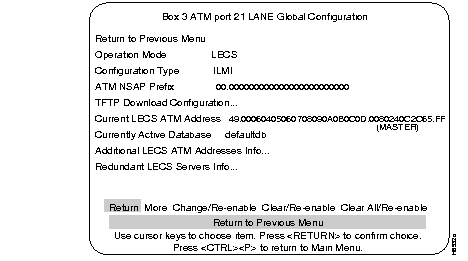
Step 3 Set the Operation Mode option to LECS.
Step 4 Return to the Configuration menu.
Step 5 Access the Reset (options) menu. Select Reset.
Use the following steps to configure the LECS, either from the console, or by way of rebooting the system using TFTP download.
Note: This feature is only available on the Catalyst 3100 and 3200 platforms
Step 1 Access the following menus:
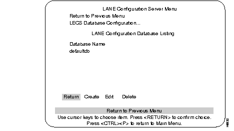
Step 2 Use either the existing defaultdb database, or create one of your own with the Create menu option.
Step 3 Select Edit for the chosen database. At the next level of the menu, use the Create option to create an entry for each VLAN you want to support on this LECS.
A LES address needs to be associated with each of the VLAN ids entered in the LECS database.The following steps describe that association.
Step 4 Access the LANE Configuration Database menu.
The LANE Configuration Database menu: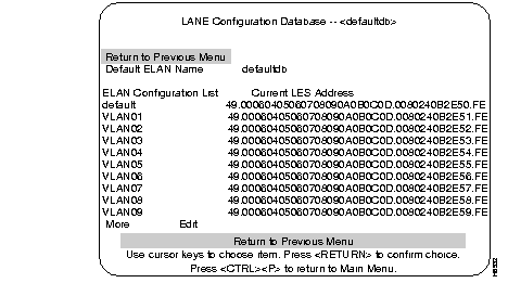
Step 5 Select the Edit option in the LANE Configuration Database menu and enter the name of one of the VLANs you created in this database. This will place you into another menu, the ELAN Configuration menu.
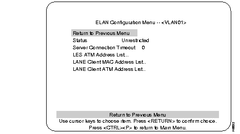
Step 6 Select the LES ATM Address List option.
Step 7 Select the Insert option. The following menu, LES ATM Address, is presented.
The LES ATM Address menu: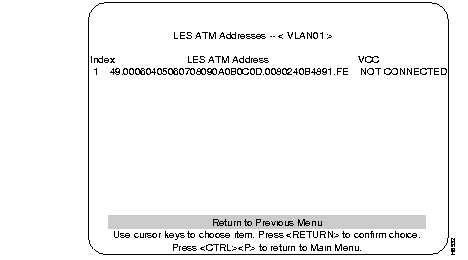
Step 8 Calculate and enter the LES address for the chosen VLAN (use the instructions in the Configuring the LECS Using A TFTP Database section for information on calculating this address). Assign an index number to the address entry and press return.
Step 9 Repeat Step 5 to Step 7 for each VLAN which needs to be supported by the LECS.
If you want to enable multiple VLAN support on the LECS, additional configuration is required. In order to support multiple VLANs on the LECS, an external database file will need to be created and placed on a TFTP server so that it can be downloaded automatically by the LECS when it boots up. Use the following steps to create this database file. If you do not wish to enable VLANs other than the default VLAN, skip to the end of this section.
In order to create entries in this database file, you will need to calculate the ESI portion (byte 13 through 19) of the LES ATM addresses for each of the VLANs which need to be supported. Use the following steps to calculate these addresses:
Step 1 Add the sub-interface number (in hex), as shown in the following example, to the 6 Byte MAC address for the ATM interface. The 6 Byte MAC address is found in the following order of menus:
The ATM Board MAC Address is to the right of the heading Base MAC Address. The following is an example of the calculation of the ESI address:
ATM Interface MAC address + Sub-Interface Number = New LES ESI Address
0080240B4890 + A (10 decimal) = 0080240B489A
Step 2 Structure the LES 20 Byte address by:
The resulting 20 byte address should be in the same format (ATM prefix, .LES ESI address, .FE) as shown in the following example:
13 Byte ATM prefix 6 Byte ESI 1 Byte FE suffix
49.00060405060708090A0B0C0D.0080240B489A.FE
Step 3 On your TFTP server directory, create a new file for storing the LECS database so that it can be downloaded on Catalyst switch bootup. In the following examples, this new file has been given the name "svrfile".
The following statement must appear at the top of the Database File:
lane database <desired database name>
Example:
lane database lanedb
This command indicates that the LAN Emulation database in this TFTP downloadable file has been given the name of "lanedb".
Step 4 Define each VLAN you wish to use and associate it with the LES ATM address for this VLAN. The following syntax is used to make this designation:
name <VLAN name> server-atm-address <40 byte LES ATM address>
Example:
name VLAN10 server-atm-address 49.00060405060708090A0B0C0D.0080240B489A.FE
Where VLAN10 is the actual VLAN name that is associated with the LES address (49.00060405060708090A0B0C0D.0080240B489A.FE) on the LES+BUSserver. This type of entry is required for each VLAN supported by the LECS. Repeat Step 2 for each VLAN defined so that a unique LES ATM address is created for each VLAN.
Step 5 The following statement must appear after the last LES VLAN entry in the database:
default-name <name of default VLAN>
Example:
default-name default
This defines the default VLAN name as default on this system.
The following example is what the downloadable database file should look like (includes two more VLAN examples with the same naming convention):
lane database lanedb
name default server-atm-address 49.00060405060708090A0B0C0D.0080240B4890.FE
name VLAN05 server-atm-address 49.00060405060708090A0B0C0D.0080240B4895.FE
name VLAN10 server-atm-address 49.00060405060708090A0B0C0D.0080240B489A.FE
default-name default
Step 6 If your topology was configured with a redundant LES, the entry for each of the supported VLANs would need to be repeated, specifying the ATM address of the redundant LES for this VLAN.
The following is an example of multiple entries for VLAN01:
lane database lanedb
name VLAN10 server-atm-address 49.00060405060708090A0B0C0D.0080240B489A.FE
name VLAN10 server-atm-address 48.0101010101010101010101010.00802400503A.FE
The above entries indicate that the LES associated with the 49.00060405060708090A0B0C0D prefix is the first one to be specified for VLAN10 and the entry involving prefix 48.01010101010101010101010 is the second to be specified. This represents the order in which the LECS will look for a LES+BUS server in order to enable all of the defined VLANs.
Step 7 Configure the LECS so that it loads the correct LECS database as created in the file on the TFTP Server (the database name was lanedb in the previous example). Access the following menus:
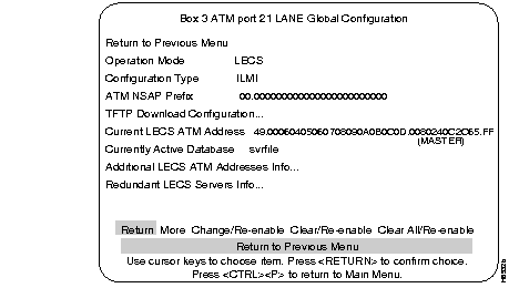
Step 8 At the LANE Global Configuration menu, select the Currently Active Database field. This field should contain the correct database name as specified in the database file (for instance, using the previous example, the field would contain lanedb).
Step 9 Configure the options for automatic download. Using the console, access the following menus:
The TFTP Download Configuration menu:
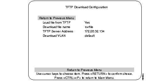
The options to configure for automatic download are:
Ensure that the Catalyst 3000 series switch configured for LECS is connected to the IP network and that it has connectivity to the server where the database file is resident. See the section on IP addresses in Chapter 7 in the appropriate Catalyst 3000 series Installation and Configuration Guide for more information on configuring an IP address on the switch.
Step 10 Configure the correct ATM address of the LECS into the ATM switch being used. You will need to calculate the ESI portion of this address. From the console access the following menus:
Step 11 Retrieve the system MAC address. To this address, add a value of hex 0x20 and the slot number where the configured ATM interface resides (slot number value must be in hex).
System Base MAC Address + Fixed Value of 0x20 + ATM Slot Number = LECS ESI Address
00802415CA50 + 0x20 + 0x15 (21 decimal) = 00802415CA85
Step 12 Use the ATM prefix, LECS ESI Address, and a selector byte value of FF to form the ATM address for LECS. The new address format is shown in the following example:
<ATM Prefix>.<LECS ESI Address>.FF
49.00060405060708090A0B0C0D.00802415CA85.FF
Restart the Catalyst 3000 series switch. The database file will be automatically downloaded after the menu interface becomes available.
Use the following steps to configure the ATM interface of a Catalyst 3000 series switch to act as a LAN Emulation Server (LES)/ Broadcast and Unknown Server (BUS):
Step 1 From the console, access the following menus:
Step 2 Set the Operation Mode option to LES/BUS. Return to the Configuration menu.
Step 3 Return to Main menu
Step 4 Access the Reset (options) menu and select Reset.
Enabling support for certain VLANs on the LES+BUS can be done two ways:
The following sections describe how to enable VLANs on the LES+BUS.
Step 1 Access the following menus:
Step 2 For each VLAN which you would like supported by the LES+BUS:
Step 3 Use the cursor keys to go back up to the Sub-Interface field to choose another number.
Step 4 Repeat this process for each VLAN the LES+BUS needs to support.
Step 1 In the TFTP directory of an accessible server, create a new file for the purpose of storing the LES+BUS s VLAN enable database.
Step 2 Using the following format, enter each of the VLANs that need to be supported by the LES+BUS:
lane server-bus ethernet<VLAN name><Slot Number of ATM card><Sub-interface number>
Example:
lane server-bus ethernet VLAN05 21 5
In this example, VLAN05 is the specific VLAN identifier in this entry, 21 represents the physical slot number where the ATM card configured for the LES+BUS is located, and 5 represents the sub-interface number as it is defined on the LECS.
Step 3 Create an entry for each VLAN to be supported.
Step 4 Save and close the file.
Step 5 From the systems console screen, access the following menus:
Modify the TFTP download configuration in the following ways:
This will allow the database download utility to automatically download the LES+BUS database each time the system is booted up.
Step 6 Return to the Reset menu and select Reset so that the database will be loaded.
Step 7 After the Catalyst 3000 series switch has reset, access the following menus:
Step 8 Check each VLAN id to ensure that the database was properly configured and downloaded. To access the different VLANs, go to the sub-interface field and enter the sub-interface number of the VLAN you want to verify.
LANE Server/BUS Configuration menu: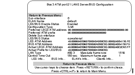
Selecting LES Info at the LANE Server/BUS Configuration menu takes you to the LANE Server Information menu. This menu displays the active LANE Clients connected to the LES.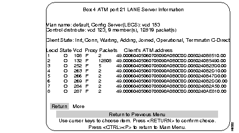
Selecting BUS Info at the LANE Server/BUS Configuration menu takes you to the LANE BUS Information menu. This menu shows the active LANE Clients that are connected to the BUS.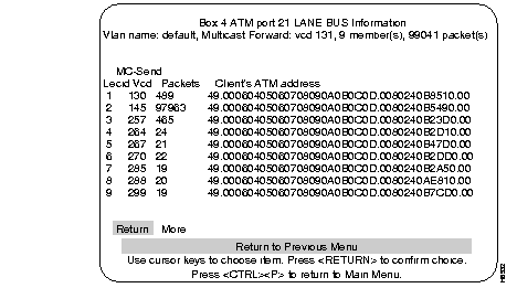
Selecting ELAN's Info at the LANE Server/BUS Configuration menu takes you to the LANE BUS Information menu. This menu lists the ELAN name, LES address, and the number of LANE Clients that are operational on each ELAN.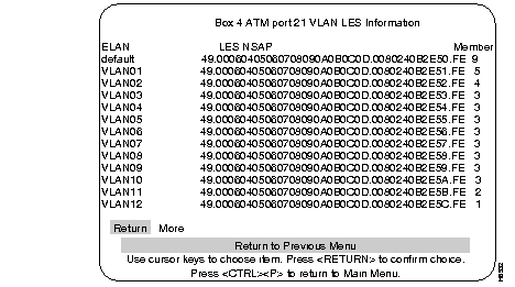
Selecting Client's Info at the LANE Server/BUS Configuration menu takes you to the LANE Server Client Information menu. This menu displays the LANE Server Client information.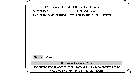
In order to configure an ATM interface of a Catalyst 3000 series system to function as both a LES+BUS and a LECS, the following steps are necessary to configure the system:
Step 1 Power up the un-initialized Catalyst 3000 series switch running software release 2.1.
Step 2 Access the following menus:
The ATM LANE Global Configuration menu: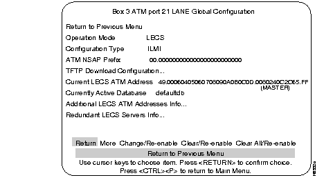
Step 3 Set the Operation Mode option to LECS and LES+BUS.
Step 4 Access the Reset (options) menu. Select Reset the switch without running diagnostics.
Step 5 Depending upon your configuration, follow the steps in the section Configuring the LECS from the Console, to configure the LECS using the console OR follow the steps in the section, Configuring the LECS Using A TFTP Database, to configure the LECS using TFTP.
Step 6 Depending upon your configuration, follow the steps in the section Enabling VLANs from the Console to enable the VLANs from the console OR follow the steps in the section, Enabling VLANs Automatically Using TFTP Downloadable Database to enable the VLANs using TFTP.
The following steps are necessary to configure and activate LAN Emulation clients on the Catalyst 3000 series switch:
Step 1 Power up the Catalyst 3000 series switch unit running software release 2.1.
Step 2 Access the following menus:
Step 3 From the VTP VLAN Configurations menu select the Add Option. While still in the VTP VLAN Configuration menu, you are prompted to enter a VLAN index number.
The VTP VLAN Configurations menu:
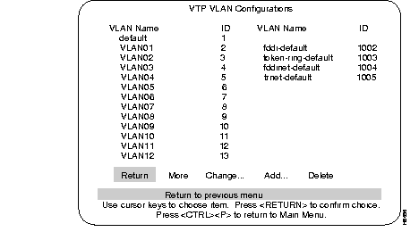
Step 4 Choose an unused number between 2 and 1001 and enter that number.
A new screen, VTP VLAN Parameter Configuration, will show the selected VLAN ID number. Just below this number is a field which stores the VLAN name for this VLAN index ID.
The VTP VLAN Parameter Configuration menu:
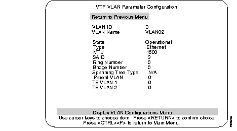
Step 5 Access the VLAN Name field and enter the VLAN name you wish to install on this system.
Step 6 Repeat Step 4 and Step 5 for each VLAN that is to be installed.
Step 7 When you are finished defining new VLAN names, select the return option to return to the VTP and VLAN sub-menu.
It is now necessary to associate at least one physical ethernet port with each VLAN so that the system will build the circuit from the LEC to the LES.
Step 8 Access the following menus:
The Local VLAN Port Configuration menu: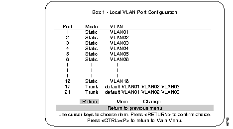
Step 9 At the Local VLAN Port Configuration menu, move the cursor to the right to select the Change option and enter the desired port number. Press RETURN.
Step 10 Using the cursor keys, move the cursor to the appropriate VLAN identifier you wish to associate with the selected port. When the cursor is on the correct identifier, press the SPACE key once to move the selection asterisk to this choice. Press RETURN.
Step 11 Repeat this process for each port you wish to associate with a VLAN. Each of the affected VLANs should now come up on this LEC.
Step 12 From the same menu, select the Change option and enter the slot number of the ATM card configured as the client. When the VLAN selection screen is shown, select each VLAN you want supported over this ATM trunk and press the SPACE key to enable it (apparent by an asterisk). Exit this menu.
Step 13 Verify that the LEC connection has been established by viewing the LANE Client Configuration menu. To view the LANE Client Configuration menu, access the following menus:
The LANE Client Configuration menu: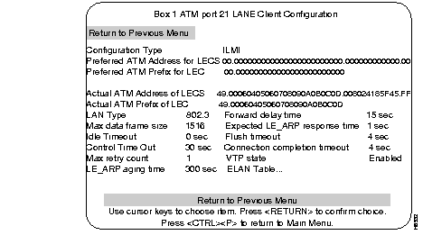
Step 14 Verify that the proper LECS address is reported in the Actual ATM Address of LECS field.
Step 15 While still in the LANE Client Configuration menu, select the ELAN Table heading (lower right section of the menu) to view the VLAN connection status. Ensure that each VLAN that was enabled in Step 4 through Step 11 of this section show a LEC state of Up.
The LANE SSRP feature provides additional, redundant LECS and LES components. The additional LECS is called a Backup LECS and the additional LES is called a secondary LES.
If the current Master LECS stops functioning, a Backup LECS becomes the new Master.
If the current primary LES stops functioning, a secondary LES becomes the new primary.
The following sections explain how LECS Master/Backup and LES primary/secondary work.
The Master LECS is the first active LECS from the top of the list of LECS addresses configured in the ATM switch. The Backup LECSs are the remaining standby LECSs in the list.
A Backup LECS becomes the Master LECS when the Master loses connectivity to the already established connections in the ATM network, including the VCC to the Backups. The first active Backup in the ATM LECSs list becomes the Master. This new Master becomes active as soon as it establishes VCCs to the LECSs below it in the address list.
Anytime an LECS detects that an LECS above it in the list has established VCC to it, then the lower LECS becomes a Backup and lets the higher, active LECS become the Master. The Backup then tears down the VCC to all of the LESs.
As soon as the VCC to an LES from LECS is torn down, the LES establishes a VCC to the new Master and reconfirms all of the LANE Clients by issuing configuration requests. If an LEC is not confirmed, the LES tears down VCCs to that LEC and the LEC reinitiates connection to the ATM network.
When the Backup becomes the Master, it affects the LES and LECs in the ATM network in the following ways:
The primary LES is the first active LES in the list from the top of LES addresses for an ELAN in the LECS database. The secondary LESs are the remaining standby LESs in the list.
An active LES is always operational and ready to accept LECs if the LEC wishes to use this LES.
When the primary LES becomes ineffective and tears down its VCC to the LECS, it also tears down VCCs to all the LECs. As soon as an LEC loses its VCCs to the LES, it reinitiates the connection procedures by issuing the LANE Configure Request to the LECS and obtains the active LES address which is considered the new primary LES.
As soon as the Master LECS knows that an LES above the current primary LES has established VCC, it tears down the VCC to the current primary LES which in turn, drops all of the VCCs to the LECs which were associated with it. Once an LEC loses VCCs to the LES, it initiates the connection procedures by obtaining the LES address from the LECS which provides the new primary LES address to the LEC.
The following are examples of ATM Statistics menus with various types of information. Explanations of the different types of VCCs follow these menus. For a complete explanation of Statistic menus see the Catalyst 3000 series Installation and Configuration Guide.
An example of a display for channel information in LEC mode: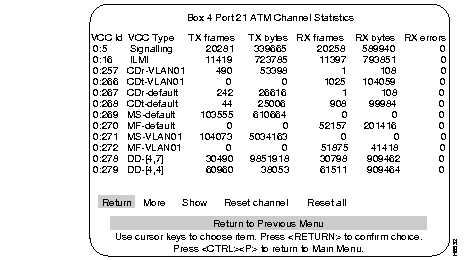
An example of a display for channel information in LECS mode: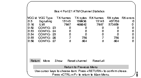
An example of a display for channel information in LES mode: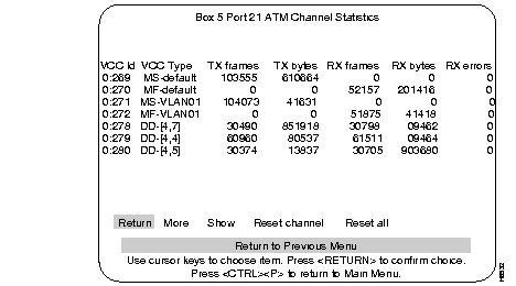
An example of a display for channel information in LES mode: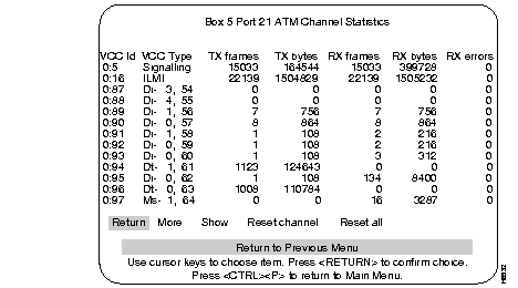
The Client end of a Control Direct channel has the VCC type of CDr-xxx. The xxx is the ELAN name of the VLAN the client is joined to. (The other end of the channel is the LES for the ELAN)
A Control distribute channel has the VCC type CDt-xxx. The xxx is the same as above. (The other end would be the LES for that ELAN.)
A Multicast Send channel has the VCC type of MS-xxx. The xxx is the same as above. (The other end would be the BUS for that ELAN.)
A Multicast forward channel has the VCC type MF-xxx. (The other end is the BUS for that ELAN.)
Data direct channels between clients would have the VCC type DD-xxx.
VCCs whose local ends are a LECS on the switch have the VCC type Config-xx. The xx is the VC number (not VCI) of the channel. The other end will usually be an LES for one of the ELANs. Such channels also exist between the LECS and Clients but these usually are not reported because of short transitions.
LES ends of Control direct channels have the VCC type Di-m,n. The m is the subinterface for this LES and n is the VC number (not VCI).
LES ends of Control distribute channels have the VCC type Dt-m,n (m,n is the same as above).
BUS ends of Multicast Send channels have the VCC type Ms-m,n. the m is the subinterface for this BUS and n is the VC number.
BUS ends of Multicast forward channels have the VCC type Mf-m,n. The m,n are the same as above.
In all cases there will also be one signalling channel and one ILMI channel. These are between the CAT3000 ATM interface and the ATM switch it is connected to.
With 2.1 software release, a parameter has been added to the LEC Client Configuration display. This parameter is called VLAN LEC Autocreation. Previously LECs were automatically created whenever a VLAN appears on the Stack and that VLAN has a local port assigned to it. LECs need to be specifically enabled before they will be on the VLAN.
The VLAN LEC Autocreation controls the creation of LECs via the VLAN-allow mask configured from the Local VLAN Port Configuration function. This menu is accessed through the VLAN and VTP Configuration menu. When VLAN LEC autocreation is enabled, VLANs are allowed by default as they appear. (New VLANs are always allowed by default on an ISL trunk). When VLAN LEC autocreation is disabled, VLANs are disallowed by default as they appear. To allow the creation of the LEC when autocreation is disabled, access the VLAN Port Configuration Menu and enable the VLAN on the ATM Trunk port.
VLAN LEC autocreation also determines whether the default Ethernet VLAN can be disabled. When VLAN LEC autocreation is disabled, the default Ethernet VLAN can also be disabled (normally enabled by default). When VLAN LEC autocreation is enabled, the default Ethernet VLAN automatically becomes enabled and cannot be disabled.
For service and support for a product purchased from a reseller, contact the reseller. Resellers offer a wide variety of Cisco service and support programs, which are described in the section "Service and Support" in the information packet that shipped with your product.
For service and support for a product purchased directly from Cisco, use CCO.
CCO is Cisco Systems' primary, real-time support channel. SMARTnet customers and partners can self-register on CCO to obtain additional information and services.
Available 24 hours a day, 7 days a week, CCO provides a wealth of standard and value-added services to Cisco's customers and business partners. CCO services include product information, product documentation, software updates, release notes, technical tips, the Bug Navigator, configuration notes, brochures, descriptions of service offerings, and download access to public and authorized files.
CCO serves a wide variety of users through two interfaces that are updated and enhanced simultaneously: a character-based version and a multimedia version that resides on the World Wide Web (WWW). The character-based CCO supports Zmodem, Kermit, Xmodem, FTP, and Internet e-mail, and it is excellent for quick access to information over lower bandwidths. The WWW version of CCO provides richly formatted documents with photographs, figures, graphics, and video, as well as hyperlinks to related information.
You can access CCO in the following ways:
For a copy of CCO's Frequently Asked Questions (FAQ), contact cco-help@cisco.com. For additional information, contact cco-team@cisco.com.
Please use CCO to obtain general information about Cisco Systems, Cisco products, or upgrades. If CCO is not accessible, contact 800 553-6387, 408 526-7208, or cs-rep@cisco.com.

|
|