|
|

Table Of Contents
Catalyst 3900 Token Ring Switch Release 4.1(2) Release Note
Ordering the Catalyst 3900 Token Ring Switch User Guide
Problems Fixed in This Release
Problems Fixed in the Catalyst 3900 Series Main Image Release 4.1(2)
Problems Fixed in the ATM Firmware Image Release 1.2(5)
New Features in Release 4.1(x)
New Features in Release 4.1(1)
Amendments to the Documentation
Viewing VLAN Configuration Information
Availability of Catalyst 3900 Software Upgrades on CCO
Catalyst 3900 Token Ring Switch Release 4.1(2) Release Note
March 8, 2000
This document describes the problems fixed in Catalyst 3900 switch main image Release 4.1(2) and in ATM firmware image Release 1.2(5). It also lists the known problems for these releases and contains information about the Catalyst 3900 and Catalyst 3920 Token Ring switches that was not included in the user guides. This document is available on the Cisco Connection Documentation CD-ROM or in print.
Sections in this document include the following:
•
Ordering the Catalyst 3900 Token Ring Switch User Guide
•
•
•
•
•
Ordering the Catalyst 3900 Token Ring Switch User Guide
The Catalyst Token Ring switch Release 4.1(x) is a CCO only release. Therefore, to get a copy of the Catalyst 3900 Token Ring Switch User Guide that lists and describes each of the new features that are available in Release 4.1(x), you must either download the PDF files of the user guide from CCO or order a printed and bound copy of the manual through Cisco MarketPlace.
Note
When ordering a printed and bound copy of the user guide through the Cisco MarketPlace, specify one of the following part numbers, depending on the manual you are ordering:
•
•
Problems Fixed in This Release
This section lists the problems that have been resolved in the Catalyst 3900 series main image Release 4.1(2) and in Release 1.2(5) of the ATM firmware image.
Problems Fixed in the Catalyst 3900 Series Main Image Release 4.1(2)
The following is a list of problems found in the Catalyst 3900 series main image that have been resolved in Release 4.1(2).
Problems Fixed in the ATM Firmware Image Release 1.2(5)
The following is a list of problems found in the Catalyst 3900 ATM firmware image that have been resolved in the Release 1.2(5).
Known Problems
This section lists the currently known problems in Release 4.1(2).
Problem: Addresses across the stack are not distributed on TokenChannel ports (CSCdm32568)
Problem Description: In rare circumstances, in a stack configuration in which a TokenChannel has been configured, the address table entries for addresses learned via a TokenChannel port located on another switch in the stack are not correctly distributed across the TokenChannel.
Recommended Action: Ensure that TokenChannel traffic does not cross the stack.
Problem: Loss of power to a Catalyst Matrix causes STP to malfunction (CSCdm62365)
Problem Description: In a Catalyst Matrix stack configuration, in which multiple stacks are connected via redundant ISL uplinks and STP is enabled, the loss of power to a Catalyst Matrix in one of the connected stacks causes STP to malfunction. When this problem occurs, the information in the Spanning Tree statistics tables and the port states for the ISL port are incorrect.
Recommended Action: Reset the switches in the affected stack.
Problem: Powering off a Catalyst Matrix might cause the loss of VTP VLAN configuration information on secondary switches (CSCdm64562)
Problem Description: In a Catalyst Matrix stack configuration, the loss of power to the Catalyst Matrix might cause secondary Catalyst 3900s (which are configured as VTP clients and are not connected to the VTP server via ISL) to lose non-local VLAN information. When this problem occurs, VLANs will be missing from the VTP VLAN Configuration panel.
Recommended Action: Press the SYSREQ button on the Catalyst 3900 that is connected to the VTP Server via ISL to synchronize the VLAN information across the stack. Resetting the switches in the stack will also synchronize the VLAN information.
Problem: IP over ISL uses a ring number of zero if the ring number has not been manually configured (CSCdm67270)
Problem Description: If the ring number has not been configured for a TrCRF used for IP communication via an ISL uplink to a Catalyst 3900, the switch might generate RIFs that contain ring number zero. This problem can cause IP communication to the switch to fail because some network devices do not support a ring number of zero.
Recommended Action: Ensure that the proper ring number for the TrCRF is manually configured.
Problem: The status of a disabled ISL port might display as up and inserted (CSCdp78073)
Problem Description: A inserted link status might display on the Port Configuration panel (Inserted displays in the Status field) and Port Status panels (Yes displays in the Ins field) even when the ISL port is disabled. Switches on the other end of the ISL trunk link might also show this disabled link as up and inserted even thought the port on the Catalyst 3900 switch is disabled. When the ISL port is disabled, there are no frames forwarded by the port.
Recommended Action: Remove the cable from the ISL port.
Problem: Cisco Discovery Protocol neighbors are not being discovered in Catalyst stacks (CSCdp88897)
Problem Description: CDP packets are not sent out of the ports located on secondary boxes (box number 2 or higher) in a stack when those ports have been blocked by spanning-tree. Ports that are in forwarding mode or ports located on box 1 of the stack are not affected by this problem. Affected Catalyst 3900s will not show up on the CDP Neighbor Display panel of a Catalyst switch that is connected to a blocked port on box 2 or higher of a stack.
Recommended Action: This problem is primarily a cosmetic problem and there is no workaround.
New Features in Release 4.1(x)
This section documents the features that have been added to Catalyst 3900 Token Ring software releases 4.1(x). This section contains the following information:
•
•
New Feature in Release 4.1(2)
The following new feature has been added to the Catalyst 3900 Token Ring software Release 4.1(2).
Configuring Basic Switch and Stack Parameters
The option to configure the insert LED to blink on disabled ports has been added to the Switch Configuration panel. By configuring the insert LED to blink on ports that are disabled, you can visually identify which ports are currently disabled. When you configure the insert LEDs to blink on disabled ports, if the switch is part of a stack, the setting applies to all switches in the stack. If you enable and then disable this feature, the insert LEDs on the disabled ports will continue to blink until the switch is rebooted.
To configure the insert LED to blink on ports that are disabled, complete the following steps:
Step 1
Step 2
Step 3
Step 4
New Features in Release 4.1(1)
The following new features have been added to the Catalyst 3900 Token Ring software Release 4.1(1). For detailed information about each new feature, including how to configure them, refer to the Release 4.1(1) version of the appropriate user guide.
VTP Pruning
A feature of VTP, VTP pruning enhances the use of network bandwidth by reducing unnecessary flooded traffic (for example, broadcast and multicast traffic). VTP pruning increases the available bandwidth by restricting flooded traffic to only those ISL trunk links that the traffic must use to access the appropriate network devices. By default, VTP pruning is disabled on Catalyst 3900 switches.
Soft Error Monitoring and Remove Adapter Support
The Catalyst 3900 switch software Release 4.1(1) and later performs error detection and isolation by monitoring the Report Soft Error MAC frames generated by stations on each port. Soft errors occur during normal ring operation and do not typically disrupt traffic on the ring. However, soft errors can occur at a rate that could potentially degrade the performance of the ring.
Using the Catalyst 3900 or Catalyst 3920, you can configure soft error thresholds and sampling intervals for a port. During the interval you define, the Catalyst 3900 monitors the stations on the port and if the threshold is exceeded, the switch can be configured to generate a trap indicating the port number and station on which the threshold was exceeded. If necessary, you can issue a Remove Ring Station MAC frame to remove the station from the ring.
In summary, the Catalyst 3900 switch:
•
•
•
ISL Channels
In addition to TokenChannels configurations, with Release 4.1(1) of the Catalyst 3900 you can configure ISL Channels.
An ISL Channel is two to four parallel connections treated as a single interface. ISL Channels provide Fast EtherChannel connectivity on the Catalyst 3900. You can configure an ISL Channel between two Catalyst 3900 switches or between a Catalyst 3900 switch and a Catalyst 5000, a Token Ring ISL-capable Cisco router, or a Token Ring ISL network adapter. All connections in an ISL Channel must be FDX.
The Catalyst 3900 ISL Channels provide the following benefits:
•
•
•
Fault Tolerant Channels
With Release 4.1(1), all channel configurations (TokenChannel and ISL Channel) are fault-tolerant.
The fault-tolerant feature enables TokenChannel and ISL Channel configurations to function as long as there is at least one port active in the channel. This capability ensures that large portions of a network are not disrupted in the event a port or cable fails within the channel by transferring the traffic to one or more of the remaining ports in the channel.
A channel displays in a a reduced state on the Current Channel Information Panel when some, but not all of the ports assigned to the channel are up.
Spanning Tree Protocol Defaults
With Release 4.1(1), by default STP is enabled on all preferred VLANs. This default applies to those VLANs that are created after the Catalyst 3900 series switch is running software Release 4.1(1) or later. However, you can manually configure the TrBRF STP participation to no, IEEE, IBM and Base on Bridging Mode.
A new STP mode, Base on Bridging Mode, is available at the TrCRF level. Base on Bridging Mode enables the bridging mode of the TrCRF to determine the STP running at the TrCRF. TrCRFs with a bridging mode of SRB run the IEEE STP and TrCRFs with a bridging mode of SRT run the Cisco STP.
The default TrBRF STP is IBM. The default TrCRF STP is Base on Bridging Mode.
Amendments to the Documentation
This section contains information that was not included in the Catalyst 3900 or Catalyst 3920 User Guides. The headings in this section correspond with the applicable section titles in the documentation.
VTP and VTP Pruning
The following statement that appears in the VTP and VTP Pruning section is misleading:
"VLANs that are not configured to be eligible for pruning are always considered to be in a joining state on every trunk. VLAN 1, the default TrBRF (1005), and TrCRFs are not eligible for pruning."
This statement should read as follows:
"VLANs that are not configured to be eligible for pruning are always considered to be in a joining state on every trunk. VLAN 1, the default TrBRF (1005), and the default TrCRF (1003) are not eligible for pruning. Pruning eligibility is configured on a TrBRF basis. Therefore, if you configure a TrBRF other than the default TrBRF to be pruning eligible, all TrCRFs associated with the TrBRF are pruning eligible as well."
RMON Support
The list of the supported groups of the Token Ring extensions to the Remote Network Monitoring MIB (RFC 1513) is incomplete.
In addition to the MAC-layer statistics group, promiscuous statistics group, Token Ring ring station group, and the Token Ring ring station order group, the following two Token Ring extensions are also supported with Release 4.1(1):
•
A list of ring station entries. An entry exists for each station that is currently or has previously been detected as being physically present on the ring.
•
A list of ring station configuration control entries. Each entry controls the management of stations by a probe. One entry exists in this table for each active station in the ring station table.
Customizing the Serial Link
The following Autobaud upon Break parameter description is incorrect:
"Indicates whether the baud rate is reset when a Break key sequence (pressing Enter rapidly for five seconds) is sent or received."
Regardless of the Autobaud upon Break parameter setting, the baud rate is reset when a break sequence is sent or received. The correct description for the Autobaud upon Break parameter is as follows:
"Indicates whether the baud rate is reset after disconnecting and reconnecting the serial cable."
Also, the values 1200 and Autobaud are incorrectly documented as valid values for the Console Baud Rate parameter. The correct Console Baud Rate valid values are 2400, 4800, 9600, 38400, and 57600.
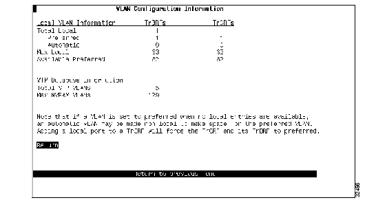
Viewing VLAN Configuration Information
An information panel, the VTP Configuration Information panel, has been added that displays how many local VLANs are currently defined and how many preferred VLANs are currently available.
To access the VTP Configuration panel, select Info on the VTP VLAN Configuration panel. The VLAN Configuration Information panel ( ) is displayed.
Figure 1 VLAN Configuration Information panel
The following information is displayed on this panel:
•
•
•
•
•
•
•
•
•
Specifying Trap Receivers
With Release 4.1(1), the maximum number of entries in the Trap Receivers list (viewable on the Trap Receivers panel) is 10. If you have more than 10 entries defined before upgrading to Release 4.1(1), the entries beyond the tenth entry are deleted when you upgrade to Release 4.1(1).
Availability of Catalyst 3900 Software Upgrades on CCO
When changes are made to the Catalyst 3900 software, the new image is posted to CCO. You can then obtain a copy of the image and download it to your switch.
Obtaining Service and Support
For service and support for a product purchased from a reseller, contact the reseller. Resellers offer a wide variety of Cisco service and support programs, which are described in the section "Service and Support" in the information packet that shipped with your product.
Note
For service and support for a product purchased directly from Cisco, use CCO.
Cisco Connection Online
Cisco Connection Online (CCO) is Cisco Systems' primary, real-time support channel. Maintenance customers and partners can self-register on CCO to obtain additional information and services.
Available 24 hours a day, 7 days a week, CCO provides a wealth of standard and value-added services to Cisco's customers and business partners. CCO services include product information, product documentation, software updates, release notes, technical tips, the Bug Navigator, configuration notes, brochures, descriptions of service offerings, and download access to public and authorized files.
CCO serves a wide variety of users through two interfaces that are updated and enhanced simultaneously: a character-based version and a multimedia version that resides on the World Wide Web (WWW). The character-based CCO supports Zmodem, Kermit, Xmodem, FTP, and Internet e-mail, and it is excellent for quick access to information over lower bandwidths. The WWW version of CCO provides richly formatted documents with photographs, figures, graphics, and video, as well as hyperlinks to related information.
You can access CCO in the following ways:
•
•
•
•
•
For a copy of CCO's Frequently Asked Questions (FAQ), contact cco-help@cisco.com. For additional information, contact cco-team@cisco.com.
Note
Ordering Documentation
Documentation for Cisco products is available in three forms: in a CD-ROM package, printed books, and on the World Wide Web. You have the option of subscribing to the CD ROM package through an update service. Or you can order printed documentation at an additional cost. Refer to the information packet included with the router for detailed ordering information. You can also access Cisco documentation on the World Wide Web URL http://www.cisco.com.
OL-6743-02 Rev. A0
![]()
![]()
![]()
![]()
![]()
![]()
![]()
![]()
Posted: Tue Apr 5 17:52:23 PDT 2005
All contents are Copyright © 1992--2005 Cisco Systems, Inc. All rights reserved.
Important Notices and Privacy Statement.