|
|

March 12, 1998
This document contains instructions for installing and configuring the Catalyst 3900 Token Ring Inter-Switch Link (ISL) module (product numbers WS-C3900-2ISL and WS-C3900-2ISLF).
Sections in this document include the following:
Along with this document, your expansion module package should contain one Token Ring ISL module. If this item is missing or damaged, contact the place of purchase.
The 2-port, 100 Mbps Token Ring ISL module supports the encapsulation of Token Ring frames on a standard Fast Ethernet link to allow Virtual LANs (VLANs) to be distributed across multiple platforms and devices. The module is available with a fiber or unshielded twisted pair (UTP)/shielded twisted pair (STP) copper media interface. The ports of the ISL module can be connected to the ports of another ISL module in another router or switch.
The Catalyst family of switches provides a means of multiplexing VLANs between switches and routers using ISL on Fast Ethernet or LAN emulation on Asynchronous Transmission Mode (ATM). You can use any combination of these trunk technologies to form enterprise-wide VLANs.
A trunk is a physical link that carries the traffic of multiple VLANs between two switches or between a switch and a router, thereby allowing the VLANs to be extended across switches. Trunks use high-speed interfaces such as Fast Ethernet, Fiber Data Distributed Interface (FDDI), or ATM.
ISL was originally developed for Ethernet switches. It uses a Fast Ethernet interface to provide connectivity between switches and extends the VLAN capabilities of the switch by tagging the standard Fast Ethernet frame with the necessary VLAN information. Like ATM, ISL can provide a high-speed link between switches. Unlike ATM, however, ISL forwards the data across the high-speed link without breaking the frames into cells. The frame is sent intact across the ISL connection.
The Token Ring implementation of ISL encapsulates Token Ring frames in Fast Ethernet frames.
In a Token Ring VLAN, logical ring domains can be formed by defining groups of ports that have the same ring number. The IEEE calls such a port group a Concentrator Relay Function (CRF). On Catalyst switches, such a grouping of Token Ring ports is called a Token Ring CRF (TrCRF).
The domain of interconnected rings is formed using an internal multiport bridge function that the IEEE calls a Bridge Relay Function (BRF). On Catalyst switches, such a grouping of logical rings is called a Token Ring BRF (TrBRF).
As mentioned in the previous section, ISL allows you to extend VLANs across switches. In a Token Ring environment, you can extend the TrBRF across switches, but not the TrCRF.
If you have an ISL module installed in your Catalyst 3900 Token Ring switch, the following types of TrCRFs can exist in your network: undistributed, backup, and default.
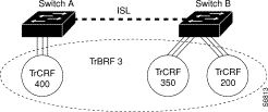
The undistributed TrCRF is the standard type of TrCRF in the Catalyst 3900 switch. The undistributed TrCRF is located on one switch and has a logical ring number associated with it. Multiple undistributed TrCRFs located on the same or separate switches can be associated with a single parent TrBRF. The parent TrBRF acts as a multiport bridge, forwarding traffic between the undistributed TrCRFs. Figure 1 illustrates the undistributed TrCRF.
The backup TrCRF enables you to configure an alternate route for traffic between undistributed TrCRFs located on separate switches that are connected by a TrBRF, in case the ISL connection between the switches becomes inactive.
While a TrBRF can contain multiple TrCRFs, it can contain only one TrCRF that is configured as a backup TrCRF. That backup TrCRF can contain only one port from each related switch. If, however, you have more than one TrBRF defined on a switch, you can have more than one backup TrCRF defined on a switch; one defined for each TrBRF.
To create a backup TrCRF, create the TrCRF, assign it to the TrBRF that traverses the switches, mark it as a backup TrCRF, and then assign one port on each switch to the backup TrCRF.
 | Caution If the backup TrCRF port is attached to a Token Ring MAU, it will not provide a backup path unless the ring speed and port mode are set by another device. Therefore, it is recommended that you manually configure the ring speed and port mode for the port assigned to the backup TrCRF. |
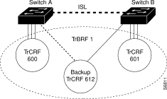
Under normal circumstances, only one port in the backup TrCRF is active. The active port is the port with the lowest MAC address. If the ISL connection between the switches become inactive, the port that is a part of the backup TrCRF on each affected switch will automatically become active, rerouting traffic between the undistributed TrCRFs through the backup TrCRF. When the ISL connection is reestablished, all but one port in the backup TrCRF will be disabled. Figure 2 illustrates the backup TrCRF.
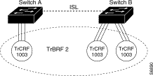
As a rule, TrCRFs cannot span different switches. There is one exception; the default TrCRF (1003). The default TrCRF can contains ports that are located on multiple switches. It is associated with the default TrBRF (1005), which can span switches via ISL. As the default TrCRF is the only TrCRF that can be associated with the default TrBRF, the default TrBRF does not perform any bridging functions, but simply uses source-route switching to forward traffic between the ports of the TrCRF. Figure 3 illustrates the default TrCRF.
The Cisco Duplicate Ring Protocol (DRiP) runs on Cisco devices that support switched VLAN networking and is used to identify active VLANs and help prevent the configuration of duplicate rings (TrCRFs) across switches.
Through packet advertisements, DRiP maintains the status of TrCRFs. It then uses this information to determine whether there are multiple TrCRFs active in a TrBRF.
DRiP information is used for the following:
While your Catalyst 3900 can contain both an ATM expansion module and an ISL expansion module, you cannot use both in a parallel configuration. If the ATM module and the ISL module are configured for parallel connections, the Spanning-Tree Protocol will allow only one of the trunk ports to be active at a time.
Because ISL is used to propagate VLAN trunking information, it is important for the ISL module to be the active path in an ISL-ATM parallel connection. Therefore, the path cost is calculated based on a 200-Mbps connection, which results in a path cost of 5 and causes the Spanning-Tree Protocol to place the ISL port in forwarding mode and the ATM port in blocked mode.
The Cisco VLAN Trunking Protocol (VTP) is used to set up and manage VLANs across an entire management domain. When new VLANs are added to a device (Cisco router or switch) in a management domain, VTP can be used to automatically distribute the information via trunk ports to all of the devices in the management domain. This distribution ensures VLAN naming consistency and connectivity between all devices in the domain by allowing each device in the domain to learn of any new VLANs added to other devices in the domain. VTP advertisements are transmitted on all ISL connections.
The Catalyst 3900 supports VTP Version 2, which includes provisions for the propagation of Token Ring-specific parameters associated with VLANs, such as hop count and bridge numbers.
The ISL module supports the Spanning-Tree Protocol at both the TrCRF and the TrBRF level. The Spanning-Tree Protocol that is run on the ISL link depends on the type of TrCRF:
The ISL module does not support passive monitoring. For active monitoring, you can monitor traffic that is processed by the ISL port on a per-TrCRF basis (monitoring only one TrCRF at a time). However, you cannot use the ISL port to monitor other ports.
TokenChannels consist of two to eight parallel channels between two Catalyst 3900s. These parallel channels can be used to provide improved performance (compared to regular Token Ring connections) between Catalyst 3900s. ISL ports, however, cannot be used in a TokenChannel.
The ISL module does not support Media Access Control (MAC) or protocol filtering.
If you want to attach the Catalyst 3900 ISL port to the ISL port of a Catalyst 5000, you must manually configure the ISL port on the Catalyst 5000 for 100 Mbps (using the set port speed command) and full-duplex mode (using the set port duplex command).
This section provides an overview of the expansion module physical characteristics.
Figure 4 shows the UTP/STP ISL module.

Figure 5 shows the fiber ISL module.

This section lists the power requirements, operating parameters, physical dimensions, and standards compliance for the ISL module.
Table 1 lists the power requirements for the ISL module.
Power consumption | 20watts |
|---|---|
Thermal dissipation | 68 BTU/hr |
Table 2 describes the operating environment for the ISL module.
Temperature | 50° F to 104° F (10° C to 40° C) |
Relative humidity | 8% to 80% |
Maximum wet-bulb temperature | 81° F (27° C) |
Table 3 lists the physical dimensions of the ISL module.
Width | 5.45 in. (138.4 mm) |
Depth | 8.06 in. (204.7 mm) |
Height | 1 in. (25.4 mm) |
Weight | 1 lb (.45 kg) |
Table 4 lists the electromagnetic interference (EMI) standards with which the ISL module complies.
STP | FCC Class A (47 CFR, Part 15), ICES-003 Class A, EN 55022 Class A, CISPR22 Class A, AS/NZS 3548 Class A, and VCCI Class A |
|---|---|
UTP | EN 55022 Class B; CISPR22 Class B, AS/NZS 3590 Class B, and VCCI Class B |
Fiber | EN 55022 Class B; CISPR22 Class B, AS/NZS 3590 Class B, and VCCI Class B |
There is one status LED for the module. It is the DIAG LED. The DIAG LED is lit during power-up diagnostics. If one of the ports on the module fails the diagnostic tests, the DIAG LED will remain lit. Otherwise, it is off.
There are three status LEDs for each of the ports. Table 5 lists the port LEDs and their meanings.
| LED | State | Meaning |
|---|---|---|
XMT | On | Port is transmitting. |
RCV | On | Port is receiving. |
LNK/FDX | On | Port is inserted into the network and is functioning in full-duplex mode. This LED is also on briefly at the end of the power-on sequence. |
Observe the following cautions when installing an expansion module into an expansion slot of the Catalyst 3900 chassis.
 | Caution Do not touch the components or connectors on the module. Do not touch cable connector pins when the other end of the cable is plugged in. Damage may result from static discharge. |
 | Caution During installation, the connector on the expansion module must line up evenly with the connector inside the expansion slot. Misalignment may cause the connector pins to bend. When inserting the expansion module into the expansion slot, be sure that the board is level and that the left and right sides slide evenly into the slot. |
 | Caution This module contains static-sensitive devices. Please follow proper electrostatic discharge (ESD) handling procedures (wristband with ground strap and ESD mat) when installing this module in your Token Ring switch chassis. |
To install the module, perform the following steps:
 | Warning Unplug the power cord before you work on a system that does not have an on/off switch. |
Step 2 Remove the expansion slot faceplate by unscrewing the thumbscrews.
Step 3 Slide the module into the slot, being careful to align the sides of the module with the guide rails (Figure 6). Continue sliding the module into the slot until it is seated in the connector at the back of the slot. When the card is fully seated, the back of the module faceplate will be in contact with the front of the Catalyst 3900.
Step 4 Secure the card using the two thumbscrews attached to it.

After you have installed the module, perform the following steps to verify the installation:
Step 2 Verify that the Catalyst 3900 diagnostics have been completed successfully. With the Catalyst 3900 ISL expansion module, this is indicated when the DIAG LED is off. Diagnostics can take up to four minutes to complete.
The ISL module's network port is either an RJ-45 or SC-style connector, depending upon the model. The RJ-45 connector uses UTP Ethernet Category 5 cable. The SC connector uses 1300 nm multimode fiber optic cable.
When cabling the ISL module, the polarity of the fiber cable connectors must be "crossed-over." The TX (transmit) connector of one device goes to the RX (receive) connector of the other device. Check the polarity of each side of the fiber-optic cable. Use one side of the fiber-optic cable to connect from the transmit (Tx) side of a dual-port fiber ISL module to the receive (Rx) side of another device. Use the other side of the cable to connect the receive side of the dual-port fiber ISL module to the transmit side of the other device.
Observe the following warnings when cabling an expansion module with fiber-optic cable.
Warning 
Laser radiation is present when the system is open.
Warning 
Do not stare into the laser beam.
The Catalyst 3900 allows you to configure the ISL expansion module using its menu-driven interface. This section describes the configuration panels that have been modified for the ISL module. For information about other configuration panels, see the Catalyst 3900 Token Ring Switch User Guide.
To access the configuration panels, select Configuration from the Main Menu. The Configuration Menu panel (Figure 7) is displayed.
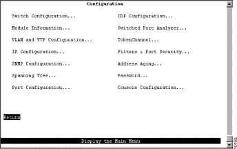
The Switch Configuration, Module Information, VLAN and VTP Configuration, Port Configuration, and Switched Port Analyzer options have been modified to accommodate the configuration of the ISL expansion module.
The Catalyst 3900 allows you to disable the ARE reduction feature provided by the ISL module. To change the current setting for ARE reduction, select Switch Configuration on the Configuration Menu. The Switch Configuration panel (Figure 8) is displayed.

The following information is displayed on this panel:
| To | Select | Then |
|---|---|---|
Change the current settings... | The appropriate parameter... | Specify the new value. |
View additional information about the switch... | Stack Information | Refer to the "Viewing Stack Information" section in the Catalyst 3900 Token Ring Switch User Guide. |
Save your changes... | Return |
|
To view general information about the Catalyst 3900 and any expansion modules installed, select Module Information on the Configuration Menu. The Module Information panel (Figure 9) is displayed.
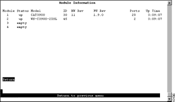
The following information is displayed on this panel:
You cannot change the information that appears on this panel.
To define VLANs or view the current definition of an existing VLAN, select VTP VLAN Configuration on the VLAN and VTP Configuration panel. The VTP VLAN Configuration panel (Figure 10) is displayed. The VTP VLAN Configuration panel has been modified. The panel now indicates which VLANs (TrBRFs and TrCRFs) are used by the local switch.

The following information is displayed on this panel:
| To | Select | Then |
|---|---|---|
View the current configuration of a VLAN, including a list of associated ports for a TrCRF... | View | Specify the VLAN ID. |
Add a new TrBRF VLAN configuration... | Add | Specify the VLAN ID. Select TrBRF. Refer to the "Adding or Changing TrBRF VLAN Parameters" section of the Catalyst 3900 Token Ring Switch User Guide. |
Add a new TrCRF VLAN configuration... | Add | Specify the VLAN ID. Select TrCRF. Refer to the "Adding or Changing TrCRF VLAN Parameters" section of the Catalyst 3900 Token Ring Switch User Guide. |
Change an existing TrBRF VLAN configuration... | Change | Specify the VLAN ID and refer to the "Adding or Changing TrBRF VLAN Parameters" section of the Catalyst 3900 Token Ring Switch User Guide. |
Change an existing TrCRF VLAN configuration... | Change | Specify the VLAN ID and refer to the "Adding or Changing TrCRF VLAN Parameters" section of the Catalyst 3900 Token Ring Switch User Guide. |
Add or remove a TrBRF or TrCRF from the list of preferred VLANS... | Change_Local_State | Specify the VLAN ID and confirm your request to add or remove the VLAN from the preferred list. Then, press any key to refresh the panel. |
Delete a VLAN... | Delete | Specify the VLAN ID. |
Display a list of VLANs sorted by VLAN ID... | Sort | Select Sort_by_VLAN_ID. |
Save your changes... | Return |
|
As described in the "ISL and VLANs" section, you can configure a TrCRF as a backup path in the event that the ISL link fails. When configuring a backup TrCRF, keep the following in mind:
To add a backup TrCRF, select Add on the VLAN Configuration panel, and select TrCRF. The VTP VLAN Parameter Configuration panel (Figure 11) is displayed.
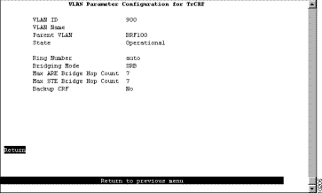
The following information is displayed on this panel:
By default, all local TrCRFs and TrBRFs that are defined on a switch when the switch is started (or restarted) are enabled for the ISL port. However, you can disable a TrCRF or TrBRF for the ISL port. To display a list of the current VLAN port assignments and to change any of these assignments, select Local VLAN Port Configuration on the VLAN and VTP Configuration panel. The Local VLAN Port Configuration panel (Figure 12) is displayed.
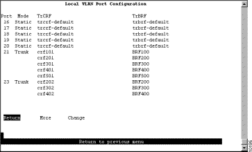
This panel displays the following information about the VLAN port assignments:
| To | Select | Then |
|---|---|---|
Change the TrCRF to which the port is assigned... | Change | Specify the port to change and select the VLAN from the displayed list of TrCRFs. |
Change the TrCRFs or TrBRFs enabled for an ISL port ... | Change | Specify the ISL port to change, select the TrBRF from the list of TrBRFs and enable or disable the TrCRF as desired. |
Save your changes... | Return |
|
When changing VLAN assignments for an ISL module, keep the following in mind:
To configure port parameters your ISL expansion module, select Port Configuration from the Configuration Menu panel. You are prompted to specify the port you want to configure. When you specify a port on an ISL module, the ISL Port Configuration panel (Figure 13) is displayed. The possible port values for the 2-port ISL expansion module are 21 and 23 (if the module is inserted in slot 1) and 25 and 27 (if the module is inserted in slot 2).
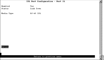
The following information is displayed on this panel:
You can use the Switched Port Analyzer (SPAN) function to perform active monitoring of your ISL module. To configure a SPAN port, select Switched Port Analyzer on the Configuration Menu. The Switched Port Analyzer panel (Figure 14) is displayed.
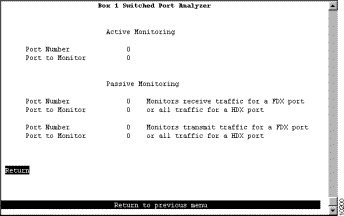
The following information is displayed on this panel:
| To | Select | Then |
|---|---|---|
Change the current settings | The appropriate parameter | Specify the value. |
Disable the SPAN port | Port to Monitor | Specify 0. |
Save your changes | Return |
|
The Catalyst 3900 provides status and statistical information for several aspects of the ISL expansion module. This section describes the status and statistics panels that have been modified for the ISL module. For information about other status and statistics panels, see the Catalyst 3900 Token Ring Switch User Guide.
To access the status and statistical information, select Statistics on the Main Menu. The Statistics panel (Figure 15) is displayed.

The Switch Statistics, Port Status, and Port Statistics options have been modified to provide information about the ISL expansion module.
To view statistics about DRiP, select Switch Statistics on the Statistics Menu. The Switch Statistics panel (Figure 16) is displayed. The information on the statistics panels is refreshed approximately every 5 seconds. To reset the information displayed on any of the statistics panels, select Reset.
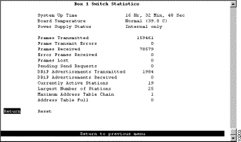
The following information is displayed on this panel:
To view status information about the ISL ports, select Port Status on the Statistics panel. The Port Status panel (Figure 17) is displayed.
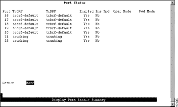
The following information is displayed on this panel:
You cannot change any information on this panel.
To access statistics about the ISL ports, select Port Statistics on the Statistics Menu panel and specify the port identifier of the ISL port. The Port x ISL Statistics panel (Figure 18) is displayed.

The following options are displayed on this panel:
To view general statistical information about the traffic on the ISL port, select General Statistics on the Port x ISL Statistics panel. The Port x General Statistics panel (Figure 19) is displayed. As the Token Ring ISL module encapsulates Token Ring frames in Ethernet frames, the frame counters on this panel pertain to the Ethernet frames transmitted and received by the ISL module.
The information on the statistics panels is refreshed approximately every 5 seconds. To reset the information displayed on any of the statistics panels, select Reset.
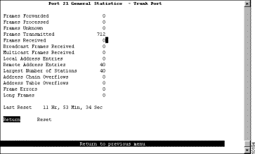
The following information is displayed on this panel:
To view statistical information about errors detected on the ISL port, select Error Statistics on the Port x ISL Statistics panel. The Port x Error Statistics panel (Figure 20) is displayed. The information on the statistics panels is refreshed approximately every 5 seconds. To reset the information displayed on any of the statistics panels, select Reset.
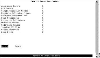
The following information is displayed on this panel:
To view statistical information about traffic processed on each VLAN by the ISL port, select VLAN Statistics on the Port x ISL Statistics panel. The Port x VLAN Statistics panel (Figure 21) is displayed. The information on the statistics panels is refreshed approximately every 5 seconds. To reset the information displayed on any of the statistics panels, select Reset.
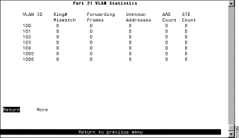
The following options are displayed on this panel:
This section contains information about working safely with electrical equipment, safety information about the module LEDs, translations of any safety warnings that appear in this document, and electronic emission notices.
 | Warning Before working on equipment that is connected to power lines, remove jewelry (including rings, necklaces, and watches). Metal objects will heat up when connected to power and ground and can cause serious burns or weld the objects to the terminals. |
 | Warning Unplug the power cord before you work on a system that does not have an on/off switch. |
Follow these guidelines when working with equipment powered by electricity:
Electrostatic discharge can damage or impair electrical circuitry. It occurs when electronic components are handled improperly. Always follow electrostatic discharge prevention procedures when removing or replacing components. Ensure that the chassis is electrically connected to earth ground using an electrostatic discharge mat or a ground wire. Wear an electrostatic discharge-preventive wrist strap, ensuring that it makes good skin contact and is connected to an unpainted surface on the chassis frame. If no wrist strap is available, ground yourself by touching the metal part of the chassis while handling a component.
The ISL module contains LEDs. The expansion module is classified as a Class 1 LED product and is certified to conform to the requirements of EN60825-1:1994 and IEC825-1:1993.
Class 1 laser products are not considered hazardous. The fiber ISL module has embedded Class 3a LED assemblies operating at a nominal wavelength of 850 nanometers and a maximum potential output power of 1.25 milliwatts. The design of the fiber ISL Ring module incorporates engineering features including current limiting, which ensures that there is no human access to LED radiation greater than Class 1 under any set of operating, maintenance, or service conditions, including a single fault.
There are fewer than 0.442 milliwatts propagating in the link or in any portion of the module. Therefore, according to IEC825-2:1993, Hazard Level 1 prevails in all parts of the system.
The LEDs are located on the front face of the module.
Safety warnings appear throughout this publication in procedures that, if performed incorrectly, may harm you. A warning symbol precedes each warning statement.
Warning 
Means danger. You are in a situation that could cause bodily injury. Before you work on any equipment, be aware of the hazards involved with electrical circuitry and be familiar with standard practices for preventing accidents. To see translations of the warnings that appear in this publication, refer to the Regulatory Compliance and Safety Information document that accompanied this device.
Waarschuwing Dit waarschuwingssymbool betekent gevaar. U verkeert in een situatie die lichamelijk letsel kan veroorzaken. Voordat u aan enige apparatuur gaat werken, dient u zich bewust te zijn van de bij elektrische schakelingen betrokken risico's en dient u op de hoogte te zijn van standaard maatregelen om ongelukken te voorkomen. Voor vertalingen van de waarschuwingen die in deze publicatie verschijnen, kunt u het document Regulatory Compliance and Safety Information (Informatie over naleving van veiligheids- en andere voorschriften) raadplegen dat bij dit toestel is ingesloten.
Varoitus Tämä varoitusmerkki merkitsee vaaraa. Olet tilanteessa, joka voi johtaa ruumiinvammaan. Ennen kuin työskentelet minkään laitteiston parissa, ota selvää sähkökytkentöihin liittyvistä vaaroista ja tavanomaisista onnettomuuksien ehkäisykeinoista. Tässä julkaisussa esiintyvien varoitusten käännökset löydät laitteen mukana olevasta Regulatory Compliance and Safety Information -kirjasesta (määräysten noudattaminen ja tietoa turvallisuudesta).
Attention Ce symbole d'avertissement indique un danger. Vous vous trouvez dans une situation pouvant causer des blessures ou des dommages corporels. Avant de travailler sur un équipement, soyez conscient des dangers posés par les circuits électriques et familiarisez-vous avec les procédures couramment utilisées pour éviter les accidents. Pour prendre connaissance des traductions d'avertissements figurant dans cette publication, consultez le document Regulatory Compliance and Safety Information (Conformité aux règlements et consignes de sécurité) qui accompagne cet appareil.
Warnung Dieses Warnsymbol bedeutet Gefahr. Sie befinden sich in einer Situation, die zu einer Körperverletzung führen könnte. Bevor Sie mit der Arbeit an irgendeinem Gerät beginnen, seien Sie sich der mit elektrischen Stromkreisen verbundenen Gefahren und der Standardpraktiken zur Vermeidung von Unfällen bewußt. Übersetzungen der in dieser Veröffentlichung enthaltenen Warnhinweise finden Sie im Dokument Regulatory Compliance and Safety Information (Informationen zu behördlichen Vorschriften und Sicherheit), das zusammen mit diesem Gerät geliefert wurde.
Avvertenza Questo simbolo di avvertenza indica un pericolo. La situazione potrebbe causare infortuni alle persone. Prima di lavorare su qualsiasi apparecchiatura, occorre conoscere i pericoli relativi ai circuiti elettrici ed essere al corrente delle pratiche standard per la prevenzione di incidenti. La traduzione delle avvertenze riportate in questa pubblicazione si trova nel documento Regulatory Compliance and Safety Information (Conformità alle norme e informazioni sulla sicurezza) che accompagna questo dispositivo.
Advarsel Dette varselsymbolet betyr fare. Du befinner deg i en situasjon som kan føre til personskade. Før du utfører arbeid på utstyr, må du vare oppmerksom på de faremomentene som elektriske kretser innebærer, samt gjøre deg kjent med vanlig praksis når det gjelder å unngå ulykker. Hvis du vil se oversettelser av de advarslene som finnes i denne publikasjonen, kan du se i dokumentet Regulatory Compliance and Safety Information (Overholdelse av forskrifter og sikkerhetsinformasjon) som ble levert med denne enheten.
Aviso Este símbolo de aviso indica perigo. Encontra-se numa situação que lhe poderá causar danos físicos. Antes de começar a trabalhar com qualquer equipamento, familiarize-se com os perigos relacionados com circuitos eléctricos, e com quaisquer práticas comuns que possam prevenir possíveis acidentes. Para ver as traduções dos avisos que constam desta publicação, consulte o documento Regulatory Compliance and Safety Information (Informação de Segurança e Disposições Reguladoras) que acompanha este dispositivo.
¡Advertencia! Este símbolo de aviso significa peligro. Existe riesgo para su integridad física. Antes de manipular cualquier equipo, considerar los riesgos que entraña la corriente eléctrica y familiarizarse con los procedimientos estándar de prevención de accidentes. Para ver una traducción de las advertencias que aparecen en esta publicación, consultar el documento titulado Regulatory Compliance and Safety Information (Información sobre seguridad y conformidad con las disposiciones reglamentarias) que se acompaña con este dispositivo.
Varning! Denna varningssymbol signalerar fara. Du befinner dig i en situation som kan leda till personskada. Innan du utför arbete på någon utrustning måste du vara medveten om farorna med elkretsar och känna till vanligt förfarande för att förebygga skador. Se förklaringar av de varningar som förkommer i denna publikation i dokumentet Regulatory Compliance and Safety Information (Efterrättelse av föreskrifter och säkerhetsinformation), vilket medföljer denna anordning.
Warning 
Before working on equipment that is connected to power lines, remove jewelry (including rings, necklaces, and watches). Metal objects will heat up when connected to power and ground and can cause serious burns or weld the metal object to the terminals.
Waarschuwing Alvorens aan apparatuur te werken die met elektrische leidingen is verbonden, sieraden (inclusief ringen, kettingen en horloges) verwijderen. Metalen voorwerpen worden warm wanneer ze met stroom en aarde zijn verbonden, en kunnen ernstige brandwonden veroorzaken of het metalen voorwerp aan de aansluitklemmen lassen.
Varoitus Ennen kuin työskentelet voimavirtajohtoihin kytkettyjen laitteiden parissa, ota pois kaikki korut (sormukset, kaulakorut ja kellot mukaan lukien). Metalliesineet kuumenevat, kun ne ovat yhteydessä sähkövirran ja maan kanssa, ja ne voivat aiheuttaa vakavia palovammoja tai hitsata metalliesineet kiinni liitäntänapoihin.
Attention Avant d'accéder à cet équipement connecté aux lignes électriques, ôter tout bijou (anneaux, colliers et montres compris). Lorsqu'ils sont branchés à l'alimentation et reliés à la terre, les objets métalliques chauffent, ce qui peut provoquer des blessures graves ou souder l'objet métallique aux bornes.
Warnung Vor der Arbeit an Geräten, die an das Netz angeschlossen sind, jeglichen Schmuck (einschließlich Ringe, Ketten und Uhren) abnehmen. Metallgegenstände erhitzen sich, wenn sie an das Netz und die Erde angeschlossen werden, und können schwere Verbrennungen verursachen oder an die Anschlußklemmen angeschweißt werden.
Avvertenza Prima di intervenire su apparecchiature collegate alle linee di alimentazione, togliersi qualsiasi monile (inclusi anelli, collane, braccialetti ed orologi). Gli oggetti metallici si riscaldano quando sono collegati tra punti di alimentazione e massa: possono causare ustioni gravi oppure il metallo può saldarsi ai terminali.
Advarsel Fjern alle smykker (inkludert ringer, halskjeder og klokker) før du skal arbeide på utstyr som er koblet til kraftledninger. Metallgjenstander som er koblet til kraftledninger og jord blir svært varme og kan forårsake alvorlige brannskader eller smelte fast til polene.
Aviso Antes de trabalhar em equipamento que esteja ligado a linhas de corrente, retire todas as jóias que estiver a usar (incluindo anéis, fios e relógios). Os objectos metálicos aquecerão em contacto com a corrente e em contacto com a ligação à terra, podendo causar queimaduras graves ou ficarem soldados aos terminais.
¡Advertencia! Antes de operar sobre equipos conectados a líneas de alimentación, quitarse las joyas (incluidos anillos, collares y relojes). Los objetos de metal se calientan cuando se conectan a la alimentación y a tierra, lo que puede ocasionar quemaduras graves o que los objetos metálicos queden soldados a los bornes.
Varning! Tag av alla smycken (inklusive ringar, halsband och armbandsur) innan du arbetar på utrustning som är kopplad till kraftledningar. Metallobjekt hettas upp när de kopplas ihop med ström och jord och kan förorsaka allvarliga brännskador; metallobjekt kan också sammansvetsas med kontakterna.
Warning 
Unplug the power cord before you work on a system that does not have an on/off switch.
Waarschuwing Voordat u aan een systeem werkt dat geen aan/uit schakelaar heeft, dient u de stekker van het netsnoer uit het stopcontact te halen.
Varoitus Ennen kuin teet mitään sellaiselle järjestelmälle, jossa ei ole kaksiasentokytkintä, kytke irti virtajohto.
Attention Avant de travailler sur un système non équipé d'un commutateur marche-arrêt, débrancher le cordon d'alimentation.
Warnung Bevor Sie an einem System ohne Ein/Aus-Schalter arbeiten, ziehen Sie das Netzkabel heraus.
Avvertenza Prima di lavorare su un sistema che non è dotato di un interruttore on/off, scollegare il cavo di alimentazione.
Advarsel Før det skal utføres arbeid på et system som ikke har en av/på-bryter, skal strømledningen trekkes ut.
Aviso Antes de começar a trabalhar num sistema que não possua um interruptor ON/OFF, desligue o cabo de alimentação.
¡Advertencia! Antes de trabajar sobre cualquier sistema que carezca de interruptor de Encendido/Apagado (ON/OFF), desenchufar el cable de alimentación.
Varning! Dra ur nätsladden innan du utför arbete på ett system utan strömbrytare.
Warning 
Laser radiation is present when the system is open.
Waarschuwing Laserstraling wanneer geopend.
Varoitus Lasersäteitä aukkojen ollessa avoinna.
Attention Production d'un rayonnement laser en position ouverte.
Warnung Laserstrahlung in geöffnetem Zustand
Avvertenza Emette radiazioni laser quando è aperto.
Advarsel Laserstråling er til stede når enheten er åpen.
Aviso Radiação laser presente quando aberto.
¡Advertencia! Radiación láser cuando está abierto.
Varning! Rikta inte blicken in mot strålen.
Warning 
Do not stare into the laser beam.
Waarschuwing Niet in de straal staren.
Varoitus Älä katso säteeseen.
Attention Ne pas fixer le faisceau des yeux.
Warnung Nicht direkt in den Strahl blicken.
Avvertenza Non fissare il raggio con gli occhi.
Advarsel Stirr ikke på strålen.
Aviso Não olhe fixamente para o raio.
¡Advertencia! No mirar fijamente el haz.
Varning! Laserstrålning när enheten är öppen.
This section contains statements pertaining to compliance with electronic emission regulations.
This equipment has been tested and found to comply with the limits for a Class A digital device, pursuant to Part 15 of the FCC Rules. These limits are designed to provide reasonable protection against harmful interference when the equipment is operated in a commercial environment. This equipment generates, uses, and can radiate radio frequency energy and, if not installed and used in accordance with the instruction manual, may cause harmful interference to radio communications. Operation of this equipment in a residential area is likely to cause harmful interference, in which case the user will be required to correct the interference at his own expense.
Properly shielded and grounded cables and connectors must be used in order to meet FCC emission limits. This company is not responsible for any radio or television interference caused by using other than recommended cables and connectors or by unauthorized changes or modifications to this equipment. Unauthorized changes or modifications could void the user's authority to operate the equipment.
This device complies with Part 15 of the FCC Rules. Operation is subject to the following two conditions: (1) this device may not cause harmful interference, and (2) this device must accept any interference received, including interference that may cause undesired operation.
This Class B digital apparatus meets the requirements of the Canadian Interference-Causing Equipment Regulations.
Cet appareil numerique de la classe B respecte toutes les exigences du Reglement sur le materiel brouilleur du Canada.
This product is in conformity with the protection requirements of EU Council Directive 89/336/EEC on the approximation of the laws of the Member States relating to electromagnetic compatibility. This company cannot accept responsibility for any failure to satisfy the protection requirements resulting from a non-recommended modification of the product, including the fitting of non-Cisco option cards.
This product has been tested and found to comply with the limits for Class B Information Technology Equipment according to CISPR 22 / European Standard EN 55022. The limits for Class B equipment were derived for typical residential environments to provide reasonable protection against interference with licensed communication devices.
This is a Class B product based on the standard of the Voluntary Control Council for Interference from Information Technology Equipment (VCCI). If this is used near a radio or television receiver in a domestic environment, it may cause radio interference. Install and use the equipment according to the instruction manual.
For service and support for a product purchased from a reseller, contact the reseller. Resellers offer a wide variety of Cisco service and support programs, which are described in the section "Service and Support" in the information packet that shipped with your product.
For service and support for a product purchased directly from Cisco, use CCO.
CCO is Cisco Systems' primary, real-time support channel. SMARTnet customers and partners can self-register on CCO to obtain additional information and services.
Available 24 hours a day, 7 days a week, CCO provides a wealth of standard and value-added services to Cisco's customers and business partners. CCO services include product information, product documentation, software updates, release notes, technical tips, the Bug Navigator, configuration notes, brochures, descriptions of service offerings, and download access to public and authorized files.
CCO serves a wide variety of users through two interfaces that are updated and enhanced simultaneously: a character-based version and a multimedia version that resides on the World Wide Web (WWW). The character-based CCO supports Zmodem, Kermit, Xmodem, FTP, and Internet e-mail, and it is excellent for quick access to information over lower bandwidths. The WWW version of CCO provides richly formatted documents with photographs, figures, graphics, and video, as well as hyperlinks to related information.
You can access CCO in the following ways:
For a copy of CCO's Frequently Asked Questions (FAQ), contact cco-help@cisco.com. For additional information, contact cco-team@cisco.com.
Please use CCO to obtain general information about Cisco Systems, Cisco products, or upgrades. If CCO is not accessible, contact 800 553-6387, 408 526-7208, or cs-rep@cisco.com.
Documentation for Cisco products is available in three forms: in a CD-ROM package, printed books, and on the World Wide Web. You have the option of subscribing to the CD ROM package through an update service. Or you can order printed documentation at an additional cost. Refer to the information packet included with the router for detailed ordering information. You can also access Cisco documentation on the World Wide Web URL http://www.cisco.com. 
![]()
![]()
![]()
![]()
![]()
![]()
![]()
![]()
Posted: Tue Jul 30 22:19:16 PDT 2002
All contents are Copyright © 1992--2002 Cisco Systems, Inc. All rights reserved.
Important Notices and Privacy Statement.