|
|

Table Of Contents
Installation Notes for the Cisco TwinGig Converter Module
Installing and Removing the Converter Module
Installing and Removing SFP Modules
Cisco Product Security Overview
Reporting Security Problems in Cisco Products
Product Alerts and Field Notices
Obtaining Technical Assistance
Definitions of Service Request Severity
Obtaining Additional Publications and Information
Installation Notes for the Cisco TwinGig Converter Module
This note provides the installation instructions for the Cisco TwinGig Converter Module. This document contains these sections:
•
Overview
•
•
•
•
Overview
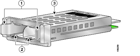
The Cisco TwinGig Converter Module (model CVR-X2-SFP), also known as the converter module, is a hot-swappable input/output (I/O) device that slides into a 10-Gigabit Ethernet slot on a Catalyst 3750-E or 3560-E switch. It converts the 10-Gigabit interface into a dual SFP interface. The converter module is shown in Figure 1.
Figure 1 Cisco TwinGig Converter Module
The converter module supports up to two small-form factor pluggable (SFP) modules. These modules plug into the converter module slots to establish fiber-optic and copper connections to network devices. Table 1 lists the SFP modules that the converter module supports.
Note
Table 1 Supported SFP Modules
GLC-GE-100FX
100BASE-FX
GLC-LH-SM
1000BASE-LX
GLC-SX-MM
1000BASE-SX
GLC-T
1000BASE-T
GLC-ZX-SM
1000BASE-ZX
GLC-BX-D
1000BASE-BX, 1490 nm1
GLC-BX-U
1000BASE-BX, 1310 nm
CWDM-SFP-1470
CWDM SFP 1470 nm
CWDM-SFP-1490
CWDM SFP 1490 nm
CWDM-SFP-1510
CWDM SFP 1510 nm
CWDM-SFP 1530
CWDM-SFP 1530 nm
CWDM SFP 1550
CWDM SFP 1550 nm
CWDM-SFP-1570
CWDM SFP 1570 nm
CWDM-SFP-1590
CWDM SFP 1590 nm
CWDM-SFP-1610
CWDM SFP 1610 nm
CAB-SFP-50CM (3560-E only)
SFP module patch cable2
1 nm = nanometer
2 The Catalyst 3560-E switch supports the SFP module patch cable, a 0-5-meter, copper, passive cable with SFP module connectors at each end. The patch cable can connect two Catalyst 3560-E switches in a cascaded configuration.
Table 2 lists the fiber-optic cabling specifications for the SFP modules that you install in the converter module. Each port must match the wave-length specifications on the other end of the cable, and the cable must not exceed the stipulated cable length.
The SFP modules using fiber-optic connections need fiber-optic cables with LC/PC connectors. The SFP modules using copper connections need Category 5 cables with RJ-45 connectors. Cooper 1000 BASE-T SFP modules use standard four twisted pair category 5 cable at lengths up to 328 feet (100 meters).
Table 2 Fiber-Optic Port Cabling Specifications
Cable Distance1000BASE-SX
850
MMF
62.5
62.5
50
50160
200
400
500722 feet (220 m)
902 feet (275 m)
1640 feet (500 m)
1804 feet (550 m)1000BASE-LX/LH
1300
MMF1
SMF62.5
50
50
G.6522500
400
500
—1804 feet (550 m)
1804 feet (550 m)
1804 feet (550 m)
32,810 feet (10 km1000BASE-ZX
1550
SMF
G.6522
—
43.4 to 62 miles (70 to 100 km)3
1000BASE-BX
1490/1310
SMF
G.6522
—
32,810 feet (10 km)
Course Wave Division Multiplexing (CWDM)
1470, 1490, 1510, 1530, 1550, 1570, 1590, 1610
SMF
G.6522
—
43.4 to 62 miles (70 to 100 km)3
1 A mode-conditioning patch cord is required. An ordinary patch cord with MMF, 1000BASE-LX/LH SFP modules, and a short link distance can cause transceiver saturation, resulting in an elevated bit error rate (BER). When using the LX/LH SFP module with 62.5-micron diameter MMF, you must also install a mode-conditioning patch cord between the SFP module and the MMF cable on both the sending and receiving ends of the link. The mode-conditioning patch cord is required for link distances greater than 984 feet (300 m).
2 ITU-T G.652 SMF as specified by the IEEE 802.3z standard.
3 1000BASE-ZX and CWDM SFP modules can send data up to 62 miles (100 km) by using dispersion-shifted SMF or low-attenuation SMF; the distance depends on the fiber quality, the number of splices, and the connectors.
Converter Module Installation
This section describes how to install and remove the converter module in a Catalyst 3750-E or 3560-E switch and how to install and remove the SFP modules. It contains these sections:
•
•
Safety Warnings
This section includes the basic installation caution and warning statements. Translations of the warning statements appear in the Regulatory Compliance and Safety Information for the Catalyst 3750-E and Catalyst 3560-E document that ships with the switch. Read this section before you start the installation procedure.
Caution
Warning
Warning
Warning
Warning
Warning
Installation Guidelines
Follow these guidelines when working with the converter module or an SFP module:
•
•
•
•
•
•
•
•
Note
Installing and Removing the Converter Module
These sections describe how to install and remove the Cisco TwinGig Converter Module in the switch 10-Gigabit Ethernet module slots.
Note
Installing the Converter Module
To install the converter module in the switch module slot, follow these steps:
Step 1
Step 2
Caution
Step 3
Caution
Caution
Step 4
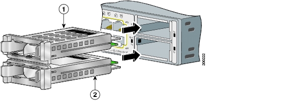
When using the switch upper 10-Gigabit Ethernet module slot (slot1), insert the converter module face up. When using the switch lower module slot (slot 2), insert the converter module face down ( Figure 2).
Step 5
Figure 2 Installing the Converter Module in the Catalyst 3750-E and Catalyst 3560-E Switch
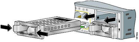
Removing the Converter Module
To remove the converter module from the switch module slot, follow these steps:
Step 1
Step 2
Step 3
Step 4
Step 5
Figure 3 Removing the Converter Module from the Catalyst 3750-E and 3560-E Switch
Installing and Removing SFP Modules
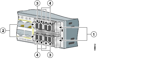
This section describes how to install and remove SFP modules in the converter module slots. You must have the converter module installed in a 10-Gigabit Ethernet switch slot to use SFP modules with the switch. Figure 4 shows the converter module in the switch with the SFP modules installed.
For detailed information about installing, removing, cabling, and troubleshooting SFP modules, see the module documentation that shipped with your device.
Caution
Note
Installing an SFP Module
Caution
To insert an SFP module into a converter module slot, follow these steps:
Step 1
Step 2
On some SFP modules, the send and receive (TX and RX) markings might be replaced by arrows that show the direction of the connection, either send (arrow pointing out) or receive (arrow pointing).
•
•
Step 3
Step 4
Step 5
Step 6
Figure 4 Converter Module with SFP Modules Installed
Converter module
Send (TX) optical bore
SFP modules1
Receive (RX) optical bore
1 Lower SFP modules are inverted.
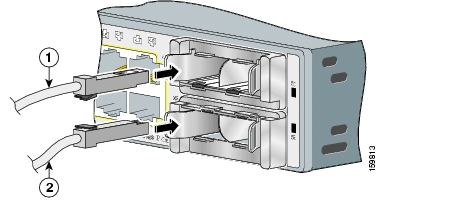
Figure 5 SFP Patch Cable Installation
Removing an SFP Module
To remove an SFP module from the converter module, follow these steps:
Step 1
Step 2
Step 3
Step 4
Step 5
Step 6
Related Publications
You can order printed copies of documents with a DOC-xxxxxx= number. For more information, see the "Obtaining Documentation" section.
These documents provide complete information about the Catalyst 3750-E and Catalyst 3560-E switch and are available on Cisco.com:
•
•
•
•
•
•
•
•
•
•
Obtaining Documentation
Cisco documentation and additional literature are available on Cisco.com. This section explains the product documentation resources that Cisco offers.
Cisco.com
You can access the most current Cisco documentation at this URL:
http://www.cisco.com/techsupport
You can access the Cisco website at this URL:
You can access international Cisco websites at this URL:
http://www.cisco.com/public/countries_languages.shtml
Product Documentation DVD
The Product Documentation DVD is a library of technical product documentation on a portable medium. The DVD enables you to access installation, configuration, and command guides for Cisco hardware and software products. With the DVD, you have access to the HTML documentation and some of the PDF files found on the Cisco website at this URL:
http://www.cisco.com/univercd/home/home.htm
The Product Documentation DVD is created and released regularly. DVDs are available singly or by subscription. Registered Cisco.com users can order a Product Documentation DVD (product number DOC-DOCDVD= or DOC-DOCDVD=SUB) from Cisco Marketplace at the Product Documentation Store at this URL:
http://www.cisco.com/go/marketplace/docstore
Ordering Documentation
You must be a registered Cisco.com user to access Cisco Marketplace. Registered users may order Cisco documentation at the Product Documentation Store at this URL:
http://www.cisco.com/go/marketplace/docstore
If you do not have a user ID or password, you can register at this URL:
http://tools.cisco.com/RPF/register/register.do
Documentation Feedback
You can provide feedback about Cisco technical documentation on the Cisco Support site area by entering your comments in the feedback form available in every online document.
Cisco Product Security Overview
Cisco provides a free online Security Vulnerability Policy portal at this URL:
http://www.cisco.com/en/US/products/products_security_vulnerability_policy.html
From this site, you will find information about how to do the following:
•
•
•
A current list of security advisories, security notices, and security responses for Cisco products is available at this URL:
To see security advisories, security notices, and security responses as they are updated in real time, you can subscribe to the Product Security Incident Response Team Really Simple Syndication (PSIRT RSS) feed. Information about how to subscribe to the PSIRT RSS feed is found at this URL:
http://www.cisco.com/en/US/products/products_psirt_rss_feed.html
Reporting Security Problems in Cisco Products
Cisco is committed to delivering secure products. We test our products internally before we release them, and we strive to correct all vulnerabilities quickly. If you think that you have identified a vulnerability in a Cisco product, contact PSIRT:
•
An emergency is either a condition in which a system is under active attack or a condition for which a severe and urgent security vulnerability should be reported. All other conditions are considered nonemergencies.
•
In an emergency, you can also reach PSIRT by telephone:
•
•
Tip
Never use a revoked encryption key or an expired encryption key. The correct public key to use in your correspondence with PSIRT is the one linked in the Contact Summary section of the Security Vulnerability Policy page at this URL:
http://www.cisco.com/en/US/products/products_security_vulnerability_policy.html
The link on this page has the current PGP key ID in use.
If you do not have or use PGP, contact PSIRT to find other means of encrypting the data before sending any sensitive material.
Product Alerts and Field Notices
Modifications to or updates about Cisco products are announced in Cisco Product Alerts and Cisco Field Notices. You can receive these announcements by using the Product Alert Tool on Cisco.com. This tool enables you to create a profile and choose those products for which you want to receive information.
To access the Product Alert Tool, you must be a registered Cisco.com user. Registered users can access the tool at this URL:
http://tools.cisco.com/Support/PAT/do/ViewMyProfiles.do?local=en
To register as a Cisco.com user, go to this URL:
http://tools.cisco.com/RPF/register/register.do
Obtaining Technical Assistance
Cisco Technical Support provides 24-hour-a-day award-winning technical assistance. The Cisco Support website on Cisco.com features extensive online support resources. In addition, if you have a valid Cisco service contract, Cisco Technical Assistance Center (TAC) engineers provide telephone support. If you do not have a valid Cisco service contract, contact your reseller.
Cisco Support Website
The Cisco Support website provides online documents and tools for troubleshooting and resolving technical issues with Cisco products and technologies. The website is available 24 hours a day at this URL:
http://www.cisco.com/en/US/support/index.html
Access to all tools on the Cisco Support website requires a Cisco.com user ID and password. If you have a valid service contract but do not have a user ID or password, you can register at this URL:
http://tools.cisco.com/RPF/register/register.do
Note
Tip
If you suspect that the browser is not refreshing a web page, force the browser to update the web page by holding down the Ctrl key while pressing F5.
To find technical information, narrow your search to look in technical documentation, not the entire Cisco.com website. After using the Search box on the Cisco.com home page, click the Advanced Search link next to the Search box on the resulting page and then click the Technical Support & Documentation radio button.
To provide feedback about the Cisco.com website or a particular technical document, click Contacts & Feedback at the top of any Cisco.com web page.Submitting a Service Request
Using the online TAC Service Request Tool is the fastest way to open S3 and S4 service requests. (S3 and S4 service requests are those in which your network is minimally impaired or for which you require product information.) After you describe your situation, the TAC Service Request Tool provides recommended solutions. If your issue is not resolved using the recommended resources, your service request is assigned to a Cisco engineer. The TAC Service Request Tool is located at this URL:
http://www.cisco.com/techsupport/servicerequest
For S1 or S2 service requests, or if you do not have Internet access, contact the Cisco TAC by telephone. (S1 or S2 service requests are those in which your production network is down or severely degraded.) Cisco engineers are assigned immediately to S1 and S2 service requests to help keep your business operations running smoothly.
To open a service request by telephone, use one of the following numbers:
Asia-Pacific: +61 2 8446 7411
Australia: 1 800 805 227
EMEA: +32 2 704 55 55
USA: 1 800 553 2447For a complete list of Cisco TAC contacts, go to this URL:
http://www.cisco.com/techsupport/contacts
Definitions of Service Request Severity
To ensure that all service requests are reported in a standard format, Cisco has established severity definitions.
Severity 1 (S1)—An existing network is "down" or there is a critical impact to your business operations. You and Cisco will commit all necessary resources around the clock to resolve the situation.
Severity 2 (S2)—Operation of an existing network is severely degraded, or significant aspects of your business operations are negatively affected by inadequate performance of Cisco products. You and Cisco will commit full-time resources during normal business hours to resolve the situation.
Severity 3 (S3)—Operational performance of the network is impaired while most business operations remain functional. You and Cisco will commit resources during normal business hours to restore service to satisfactory levels.
Severity 4 (S4)—You require information or assistance with Cisco product capabilities, installation, or configuration. There is little or no effect on your business operations.
Obtaining Additional Publications and Information
Information about Cisco products, technologies, and network solutions is available from various online and printed sources.
•
http://www.cisco.com/offer/subscribe
•
•
http://www.cisco.com/go/marketplace/
•
•
•
http://www.cisco.com/en/US/products/index.html
•
http://www.cisco.com/discuss/networking
•
http://www.cisco.com/univercd/cc/td/doc/abtunicd/136957.htm
•
http://www.cisco.com/en/US/learning/index.html
CCVP, the Cisco Logo, and the Cisco Square Bridge logo are trademarks of Cisco Systems, Inc.; Changing the Way We Work, Live, Play, and Learn is a service mark of Cisco Systems, Inc.; and Access Registrar, Aironet, BPX, Catalyst, CCDA, CCDP, CCIE, CCIP, CCNA, CCNP, CCSP, Cisco, the Cisco Certified Internetwork Expert logo, Cisco IOS, Cisco Press, Cisco Systems, Cisco Systems Capital, the Cisco Systems logo, Cisco Unity, Enterprise/Solver, EtherChannel, EtherFast, EtherSwitch, Fast Step, Follow Me Browsing, FormShare, GigaDrive, GigaStack, HomeLink, Internet Quotient, IOS, iPhone, IP/TV, iQ Expertise, the iQ logo, iQ Net Readiness Scorecard, iQuick Study, LightStream, Linksys, MeetingPlace, MGX, Networking Academy, Network Registrar, Packet, PIX, ProConnect, RateMUX, ScriptShare, SlideCast, SMARTnet, StackWise, The Fastest Way to Increase Your Internet Quotient, and TransPath are registered trademarks of Cisco Systems, Inc. and/or its affiliates in the United States and certain other countries.
All other trademarks mentioned in this document or Website are the property of their respective owners. The use of the word partner does not imply a partnership relationship between Cisco and any other company. (0612R)
![]()
![]()
![]()
![]()
![]()
![]()
![]()
![]()
Posted: Tue Feb 13 11:25:58 PST 2007
All contents are Copyright © 1992--2007 Cisco Systems, Inc. All rights reserved.
Important Notices and Privacy Statement.