|
|

Table Of Contents
Installation Notes for Catalyst 3750-E,
Catalyst 3560-E Switches and RPS 2300
Power Supply ModulesPower Supply Module Installation
Installing a DC-Power Supply (Only Catalyst 3750-E and 3560-E Switches)
Cisco Product Security Overview
Reporting Security Problems in Cisco Products
Obtaining Technical Assistance
Cisco Technical Support & Documentation Website
Definitions of Service Request Severity
Obtaining Additional Publications and Information
Installation Notes for Catalyst 3750-E,
Catalyst 3560-E Switches and RPS 2300
Power Supply Modules
This document provides the removal and installation procedures for the power supply modules used with the Catalyst 3750-E, the Catalyst 3560-E switches, and the Cisco Redundant Power System 2300 (RPS 2300).
For more information about using the power supply modules with a switch or an RPS 2300, see the Catalyst 3750-E and Catalyst 3560-E Switch Hardware Installation Guide and the Cisco RPS 2300 Hardware Installation Guide on Cisco.com.
For translations of the safety warnings that appear in this publication, see the Regulatory Compliance and Safety Information for the Catalyst 3750-E and Catalyst 3560-E Switch or the Cisco RPS 2300 Hardware Installation Guide that shipped with the product and that are also available on Cisco.com.
Contents
This document includes these sections:
•
Power Supply Module Installation
•
•
•
Product Overview
Table 1 describes the power supply modules.
Table 2 describes the supported power supply modules for the switches and the RPS 2300.
For more information about which RPS 2300 power supply modules to use for specific switch support, see the Cisco Redundant Power System 2300 Hardware Installation Guide.
Table 2 Power Supply Modules Used with Switches and RPS 2300
Power Supply
Power Supply
Power Supply
Power Supply48-port PoE switch1
Primary or spare
Spare or primary
Not allowed
Not allowed
24-port PoE switch
Spare or primary
Primary or spare
Not allowed
Not allowed
48-port non-PoE switch
Spare
Spare
Primary or spare
Primary or spare
24-port non-PoE switch
Spare
Spare
Primary or spare
Primary or spare
RPS 23002
Primary
Primary
Not allowed
Not allowed
1 For full 15.4-W support on a 48-port PoE switch, you must use the 1150-W AC power supply module in the switch.
2 If only one power supply module is installed in the RPS 2300, you must install the blank insert in the empty power supply slot.
The 750-W and 265-W AC power supply modules are autoranging units that support input voltages between 100 and 240 VAC. The 1150-W power supply module is an autoranging unit that supports input voltages between 115 and 240 VAC. The DC power supply module has dual input feeds (A and B) and supports input voltages between 36 and 72 VDC.
The AC power supply modules include a power cord for connection to an AC power outlet. The 1150-W and 750-W modules use a 16-AWG cord (only North America). All other modules use an 18-AWG cord. The DC power supply module requires wiring to a DC-power source.
Figure 1 to Figure 3 show the power supply modules.
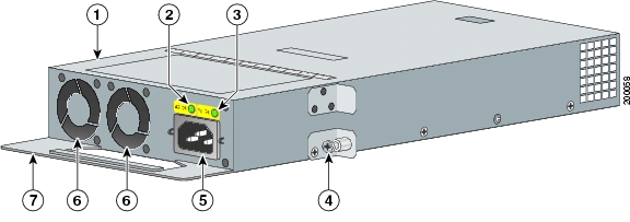
Figure 1 1150-W AC Power Supply Module
1150-W AC power supply module
AC power connector
AC OK LED
Cooling fans
PS OK LED
Extraction handle
Captive screw
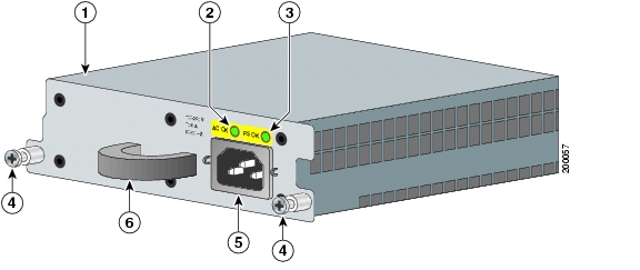
Figure 2 750-W AC and 265-W AC Power Supply Modules
750- or 265-W AC power supply module
Captive screws
AC OK LED
AC power connector
PS OK LED
Extraction handle
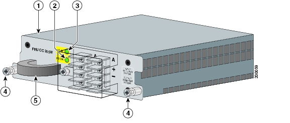
Figure 3 265-W DC Power Supply Module
265-W DC power supply module
Captive screws
Input power terminals
Extraction handle
DC OK and PS OK LEDs
The power supply modules have two status LEDs. Table 3 lists the LED colors and their meanings.
Power Supply Module Installation
This section describes how to remove and install a new or replacement power supply module in Catalyst 3750-E and Catalyst 3560-E switches, or an RPS 2300. See these sections:
•
•
Tools and Equipment
Obtain these necessary tools and equipment:
•
•
Installation Guidelines
Observe these guidelines when removing or installing a power supply module:
•
•
•
•
•
–
–
–
•
•
Warning
Warning
Warning
Installing an AC-Power Supply
To remove and install an AC-powered power supply module, follow these steps:
Step 1
Step 2
Step 3
Step 4
Caution
Step 5
Step 6
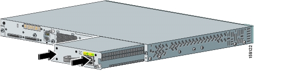
Figure 4 Inserting an AC-Power Supply into a Switch
Figure 5 Inserting an AC-Power Supply into an RPS 2300
Step 7
Step 8
Step 9
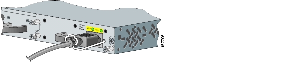
Figure 6 AC-Power Supply and Power Cord Retainer Installed in a Switch
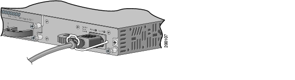
Figure 7 AC-Power Supply and Power Cord Retainer Installed in the RPS 2300
Step 10
Step 11
Installing a DC-Power Supply (Only Catalyst 3750-E and 3560-E Switches)
To connect the switch to a DC-input power source, follow these steps:
3.
4.
Warning
Warning
Warning
Note
Preparing for Installation
Obtain these necessary tools and equipment:
•
•
•
•
•
•
•
•
Grounding the Switch
Warning
Warning
Caution
Follow these steps to install either a single-ground lug or a dual-ground lug on the switch. Make sure to follow any grounding requirements at your site.
Step 1
Step 2
Figure 8 Stripping the Ground Wire
Step 3
Step 4
Figure 9 Crimping the Ground Lug
Step 5
Step 6
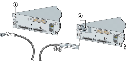
Figure 10 Attaching the Ground Lug and Wire Assembly
Step 7
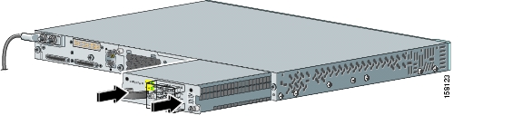
Installing the DC Power Supply in the Switch
To remove and install a DC-powered power supply module, follow these steps:
Step 1
Step 2
Step 3
Step 4
Step 5
Step 6
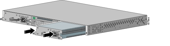
Figure 11 Inserting the a DC-Power Supply
Step 7
Step 8
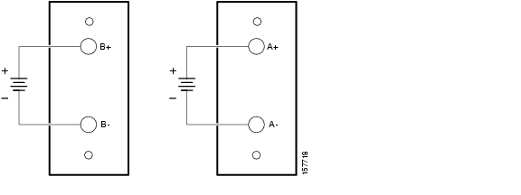
Wiring the DC-Input Power Source
To wire the DC-power supply module to a DC-input power source, follow these steps.
Step 1
Step 2
Step 3
Figure 12 Source A Isolated From Source B with No Common Ground
Step 4
Step 5
Step 6
Step 7
Technical Specifications
Related Publications
You can order printed copies of documents with a DOC-xxxxxx= number. For more information, see the "Obtaining Documentation" section.
These documents provide complete information about the switch and are available on Cisco.com:
•
•
•
•
•
•
•
•
•
•
•
Obtaining Documentation
Cisco documentation and additional literature are available on Cisco.com. Cisco also provides several ways to obtain technical assistance and other technical resources. These sections explain how to obtain technical information from Cisco Systems.
Cisco.com
You can access the most current Cisco documentation at this URL:
http://www.cisco.com/techsupport
You can access the Cisco website at this URL:
You can access international Cisco websites at this URL:
http://www.cisco.com/public/countries_languages.shtml
Product Documentation DVD
The Product Documentation DVD is a comprehensive library of technical product documentation on a portable medium. The DVD enables you to access multiple versions of installation, configuration, and command guides for Cisco hardware and software products. With the DVD, you have access to the same HTML documentation that is found on the Cisco website without being connected to the Internet. Certain products also have .PDF versions of the documentation available.
The Product Documentation DVD is available as a single unit or as a subscription. Registered Cisco.com users (Cisco direct customers) can order a Product Documentation DVD (product number DOC-DOCDVD= or DOC-DOCDVD=SUB) from Cisco Marketplace at this URL:
http://www.cisco.com/go/marketplace/
Ordering Documentation
Registered Cisco.com users may order Cisco documentation at the Product Documentation Store in the Cisco Marketplace at this URL:
http://www.cisco.com/go/marketplace/
Nonregistered Cisco.com users can order technical documentation from 8:00 a.m. to 5:00 p.m. (0800 to 1700) PDT by calling 1 866 463-3487 in the United States and Canada, or elsewhere by calling 011 408 519-5055. You can also order documentation by e-mail at tech-doc-store-mkpl@external.cisco.com or by fax at 1 408 519-5001 in the United States and Canada, or elsewhere at 011 408 519-5001.
Documentation Feedback
You can rate and provide feedback about Cisco technical documents by completing the online feedback form that appears with the technical documents on Cisco.com.
You can submit comments about Cisco documentation by using the response card (if present) behind the front cover of your document or by writing to the following address:
Cisco Systems
Attn: Customer Document Ordering
170 West Tasman Drive
San Jose, CA 95134-9883We appreciate your comments.
Cisco Product Security Overview
Cisco provides a free online Security Vulnerability Policy portal at this URL:
http://www.cisco.com/en/US/products/products_security_vulnerability_policy.html
From this site, you will find information about how to:
•
•
•
A current list of security advisories, security notices, and security responses for Cisco products is available at this URL:
To see security advisories, security notices, and security responses as they are updated in real time, you can subscribe to the Product Security Incident Response Team Really Simple Syndication (PSIRT RSS) feed. Information about how to subscribe to the PSIRT RSS feed is found at this URL:
http://www.cisco.com/en/US/products/products_psirt_rss_feed.html
Reporting Security Problems in Cisco Products
Cisco is committed to delivering secure products. We test our products internally before we release them, and we strive to correct all vulnerabilities quickly. If you think that you have identified a vulnerability in a Cisco product, contact PSIRT:
•
An emergency is either a condition in which a system is under active attack or a condition for which a severe and urgent security vulnerability should be reported. All other conditions are considered nonemergencies.
•
In an emergency, you can also reach PSIRT by telephone:
•
•
Tip
Never use a revoked or an expired encryption key. The correct public key to use in your correspondence with PSIRT is the one linked in the Contact Summary section of the Security Vulnerability Policy page at this URL:
http://www.cisco.com/en/US/products/products_security_vulnerability_policy.html
The link on this page has the current PGP key ID in use.
If you do not have or use PGP, contact PSIRT at the aforementioned e-mail addresses or phone numbers before sending any sensitive material to find other means of encrypting the data.
Obtaining Technical Assistance
Cisco Technical Support provides 24-hour-a-day award-winning technical assistance. The Cisco Technical Support & Documentation website on Cisco.com features extensive online support resources. In addition, if you have a valid Cisco service contract, Cisco Technical Assistance Center (TAC) engineers provide telephone support. If you do not have a valid Cisco service contract, contact your reseller.
Cisco Technical Support & Documentation Website
The Cisco Technical Support & Documentation website provides online documents and tools for troubleshooting and resolving technical issues with Cisco products and technologies. The website is available 24 hours a day, at this URL:
http://www.cisco.com/techsupport
Access to all tools on the Cisco Technical Support & Documentation website requires a Cisco.com user ID and password. If you have a valid service contract but do not have a user ID or password, you can register at this URL:
http://tools.cisco.com/RPF/register/register.do
Note
Submitting a Service Request
Using the online TAC Service Request Tool is the fastest way to open S3 and S4 service requests. (S3 and S4 service requests are those in which your network is minimally impaired or for which you require product information.) After you describe your situation, the TAC Service Request Tool provides recommended solutions. If your issue is not resolved using the recommended resources, your service request is assigned to a Cisco engineer. The TAC Service Request Tool is located at this URL:
http://www.cisco.com/techsupport/servicerequest
For S1 or S2 service requests, or if you do not have Internet access, contact the Cisco TAC by telephone. (S1 or S2 service requests are those in which your production network is down or severely degraded.) Cisco engineers are assigned immediately to S1 and S2 service requests to help keep your business operations running smoothly.
To open a service request by telephone, use one of the following numbers:
Asia-Pacific: +61 2 8446 7411 (Australia: 1 800 805 227)
EMEA: +32 2 704 55 55
USA: 1 800 553-2447For a complete list of Cisco TAC contacts, go to this URL:
http://www.cisco.com/techsupport/contacts
Definitions of Service Request Severity
To ensure that all service requests are reported in a standard format, Cisco has established severity definitions.
Severity 1 (S1)—An existing network is down, or there is a critical impact to your business operations. You and Cisco will commit all necessary resources around the clock to resolve the situation.
Severity 2 (S2)—Operation of an existing network is severely degraded, or significant aspects of your business operations are negatively affected by inadequate performance of Cisco products. You and Cisco will commit full-time resources during normal business hours to resolve the situation.
Severity 3 (S3)—Operational performance of the network is impaired, while most business operations remain functional. You and Cisco will commit resources during normal business hours to restore service to satisfactory levels.
Severity 4 (S4)—You require information or assistance with Cisco product capabilities, installation, or configuration. There is little or no effect on your business operations.
Obtaining Additional Publications and Information
Information about Cisco products, technologies, and network solutions is available from various online and printed sources.
•
•
http://www.cisco.com/go/marketplace/
•
•
•
http://www.cisco.com/en/US/products/index.html
•
http://www.cisco.com/discuss/networking
•
http://www.cisco.com/en/US/learning/index.html
This document is to be used in conjunction with the documents listed in the "Related Publications" section.
CCVP, the Cisco Logo, and the Cisco Square Bridge logo are trademarks of Cisco Systems, Inc.; Changing the Way We Work, Live, Play, and Learn is a service mark of Cisco Systems, Inc.; and Access Registrar, Aironet, BPX, Catalyst, CCDA, CCDP, CCIE, CCIP, CCNA, CCNP, CCSP, Cisco, the Cisco Certified Internetwork Expert logo, Cisco IOS, Cisco Press, Cisco Systems, Cisco Systems Capital, the Cisco Systems logo, Cisco Unity, Enterprise/Solver, EtherChannel, EtherFast, EtherSwitch, Fast Step, Follow Me Browsing, FormShare, GigaDrive, GigaStack, HomeLink, Internet Quotient, IOS, IP/TV, iQ Expertise, the iQ logo, iQ Net Readiness Scorecard, iQuick Study, LightStream, Linksys, MeetingPlace, MGX, Networking Academy, Network Registrar, Packet, PIX, ProConnect, RateMUX, ScriptShare, SlideCast, SMARTnet, StackWise, The Fastest Way to Increase Your Internet Quotient, and TransPath are registered trademarks of Cisco Systems, Inc. and/or its affiliates in the United States and certain other countries.
All other trademarks mentioned in this document or Website are the property of their respective owners. The use of the word partner does not imply a partnership relationship between Cisco and any other company. (0609R)
Any Internet Protocol (IP) addresses used in this document are not intended to be actual addresses. Any examples, command display output, and figures included in the document are shown for illustrative purposes only. Any use of actual IP addresses in illustrative content is unintentional and coincidental.
© 2006 Cisco Systems, Inc. All rights reserved.
Printed in China PRC
![]()
![]()
![]()
![]()
![]()
![]()
![]()
![]()
Posted: Mon Feb 12 10:10:54 PST 2007
All contents are Copyright © 1992--2007 Cisco Systems, Inc. All rights reserved.
Important Notices and Privacy Statement.