|
|

Table Of Contents
Catalyst 3750-E Switch Getting Started Guide
Downloading Cisco Network Assistant
Power On Sequence for Switch Stacks
Installation Warning Statements
Cisco Product Security Overview
Obtaining Technical Assistance
Cisco Technical Support Website
Definitions of Service Request Severity
Obtaining Additional Publications and Information
Cisco 90-Day Limited Hardware Warranty Terms
Getting Started Guide
Catalyst 3750-E Switch Getting Started Guide
INCLUDING LICENSE AND WARRANTY1 About this Guide
This guide provides instructions on how to use Express Setup to initially configure your Catalyst switch. Also covered are switch management options, basic rack-mounting procedures, stacking procedures, port and module connection procedures, and troubleshooting help.
For additional installation and configuration information for Catalyst 3750-E switches, see the Catalyst 3750-E documentation on Cisco.com. For system requirements, important notes, limitations, open and resolved bugs, and last-minute documentation updates, see the release notes, also on Cisco.com.
When using the online publications, refer to the documents that match the Cisco IOS software version running on the switch. The software version is on the Cisco IOS label on the switch rear panel.
You can order printed copies of the manuals from the Cisco.com sites and from the telephone numbers listed in the "Obtaining Documentation" section.
For translations of the warnings that appear in this publication, see the Regulatory Compliance and Safety Information for the Catalyst 3750-E and Catalyst 3560-E Switch that accompanies this guide.
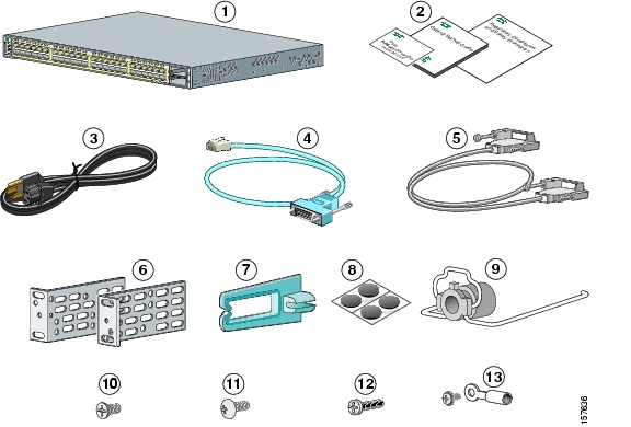
2 Taking Out What You Need
Follow these steps:
1.
Unpack and remove the switch and the accessory kit from the shipping box.
2.
3.
4.
Shipping Box Contents
Catalyst 3750E-48 Power over Ethernet (PoE) switch
Four rubber mounting feetDocumentation
Power cord retainer
AC power cord
Four number-12 Phillips machine screws
Console cable
Twelve number-8 Phillips flat-head screws
StackWise cable, 0.5-meter, 1-meter or 3-meter1
One black Phillips machine screwTwo 19-inch mounting brackets
Ground lug screw and ring terminal
Cable guide
1 (0.5-meter supplied when not specified)
3 Running Express Setup
When you first set up the switch, you should use Express Setup to enter the initial IP information. Doing this enables the switch to connect to local routers and the Internet. You can then access the switch through the IP address for further configuration.
You need this equipment to set up the switch:
•
•
•
Disable any pop-up blockers or proxy settings in your browser software and any wireless client running on your PC.
To run Express Setup:
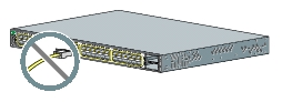
Step 1
Make sure that nothing is connected to the switch.
During Express Setup, the switch acts as a DHCP server. If your PC has a static IP address, change your PC settings before you begin to temporarily use DHCP.
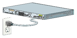
Step 2
Power the switch.
For AC-powered switches, connect the AC power cord to the switch power supply and to a grounded AC outlet.
For DC-powered switches, see the wiring instructions in the hardware installation guide on Cisco.com.
Step 3
When the switch powers on, it begins the power-on self-test (POST). During POST, the LEDs blink while tests verify that the switch functions properly.
Wait for the switch to complete POST, which can take several minutes.
Step 4
Verify that POST has completed by confirming that the SYST LED remains green. If the switch fails POST, the SYST LED turns amber. See the "In Case of Difficulty" section if your switch fails POST.
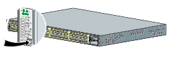
Step 5
Press and hold the Mode button for 3 seconds. When all of the LEDs above the Mode button turn green, release the Mode button.
Step 6
If the LEDs above the Mode button blink after you press the button, release it. Blinking LEDs mean that the switch is already configured and cannot go into Express Setup mode. For more information, see the "Resetting the Switch" section.
Step 7
Verify that the switch is in Express Setup mode. Make sure that all LEDs above the Mode button are green. (On some switch models, the RPS LED remains off.)
Step 8
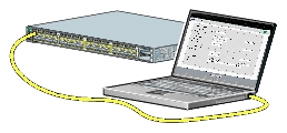
Connect a Category 5 Ethernet cable to any 10/100/1000 Ethernet port on the switch front panel or to the Ethernet management port on the rear panel. Connect the other end of the cable to the Ethernet port on your PC.
Step 9
Verify that the LEDs on both Ethernet ports are green.
Wait 30 seconds.
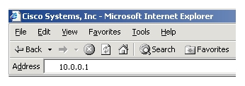
Step 10
Launch a web browser on your PC. Enter the IP address 10.0.0.1 in the web browser, and press Enter.
Step 11
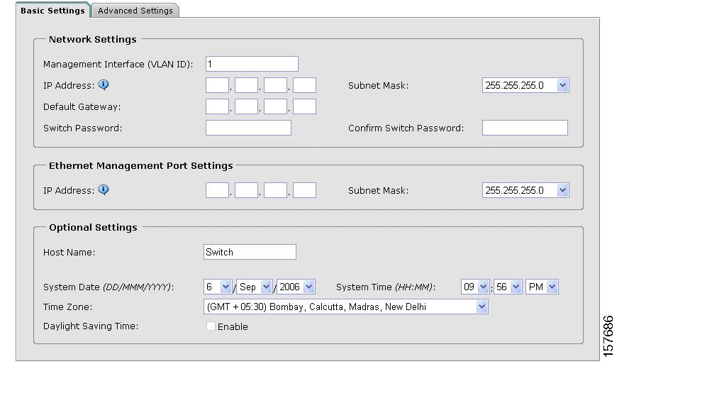
The Express Setup Basic Settings page appears. If it does not appear, see the "In Case of Difficulty" section.
Step 12
Enter this information in the Network Settings fields:
•
•
•
•
Step 13
(Optional) Enter this information in the Ethernet Management Port Settings fields:
•
Step 14
(Optional) You can enter the Optional Settings information now or enter it later by using the device manager interface:
•
•
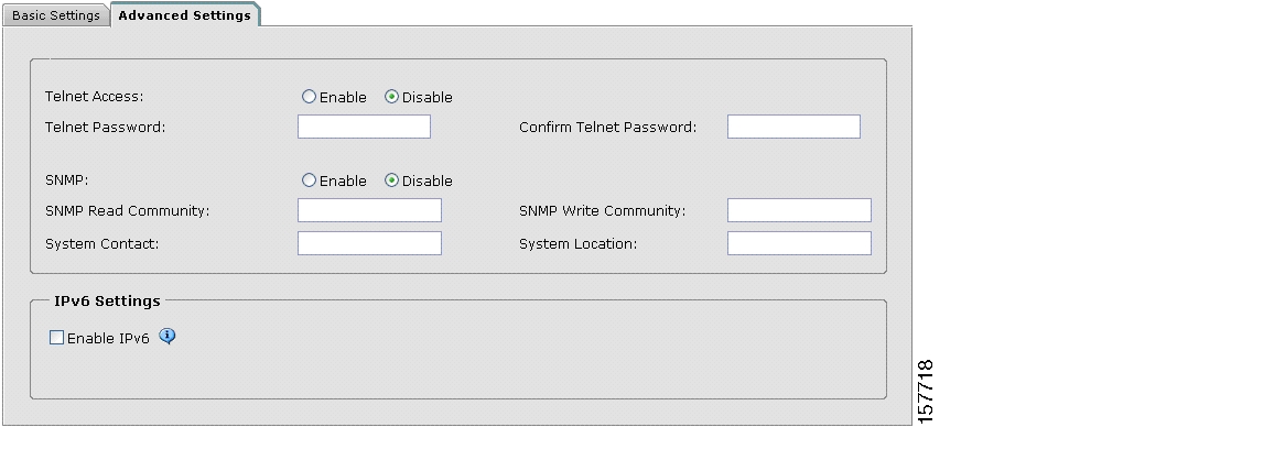
Step 15
(Optional) You can select the Advanced Settings tab on the Express Setup window and enter the advanced settings now or enter them later by using the device manager interface.
Step 16
(Optional) Enter this information in the Advanced Setting fields:
•
•
•
•
•
Step 17
(Optional) You can enable IPv6 on the switch in the Advanced Settings screen. In the Enable IPv6 field, click Enable to enable IPv6 on the switch. Note: Enabling IPv6 restarts the switch when you complete Express Setup.
Step 18
To complete Express Setup, click Submit in the Network Settings or the Advanced Settings screen to save your settings. Click Cancel to clear your settings.
When you click Submit, the switch is configured and exits Express Setup mode. The PC displays a warning message and then tries to connect with the new switch IP address. If you configured the switch with an IP address that is in a different subnet from the PC, connectivity between the PC and the switch is lost. If you enabled IPv6, the switch restarts.
Step 19
Disconnect the switch from the PC, and install the switch in your production network. See the "Managing the Switch" section for information about configuring and managing the switch.
If you need to rerun Express Setup, see the "Resetting the Switch" section.
Refreshing the PC IP Address
After you complete Express Setup, you should refresh the PC IP address:
•
•
4 Managing the Switch
After you complete Express Setup and install the switch in your network, use the device manager or other management options described in this section for further configuration.
Using the Device Manager
The simplest way to manage the switch is by using the device manager that is in the switch memory. This is a web interface that offers quick configuration and monitoring. You can access the device manager from anywhere in your network through a web browser.
Follow these steps:
1.
2.
3.
4.
Downloading Cisco Network Assistant
Cisco Network Assistant is a software program that you download from Cisco.com and run on your PC. It offers advanced options for configuring and monitoring multiple devices, including switches, switch clusters, switch stacks, routers, and access points. Network Assistant is free—there is no charge to download, install, or use it.
Follow these steps:
1.
You must be a registered Cisco.com user, but you need no other access privileges.
2.
3.
4.
Refer to the Network Assistant online help and the getting started guide for more information.
Command-Line Interface
You can enter Cisco IOS commands and parameters through the CLI. Access the CLI by connecting your PC directly to the switch console port or to the Ethernet management port.
Using the switch console port:
Follow these steps:
1.
2.
3.
4.
Using the switch Ethernet management port:
Follow these steps:
1.
2.
3.
4.
Other Management Options
You can use SNMP management applications such as CiscoWorks Small Network Management Solution (SNMS) and HP OpenView to configure and manage the switch. You also can manage it from an SNMP-compatible workstation that is running platforms such as HP OpenView or SunNet Manager.
The Cisco IE2100 Series Configuration Registrar is a network management device that works with embedded Cisco Networking Services (CNS) agents in the switch software. You can use IE2100 to automate initial configurations and configuration updates on the switch.
See the "Accessing Help Online" section for a list of supporting documentation.
5 Planning Switch Stacks
Before connecting the switches in a stack, keep in mind these stacking guidelines:
•
•
•
•
–
–
–
–
–
–
For switch dimensions, StackWise cable part numbers, and additional stacking guidelines, see the switch hardware installation guide on Cisco.com. For concepts and procedures to manage switch stacks, see the switch software configuration guide and the stack compatibility guide also on Cisco.com.
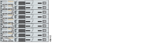
Stack Cabling Configurations
These illustrations show the recommended switch stack configurations with redundant StackWise cabling connections for optimized stack bandwidth. For more configuration examples, see the hardware installation guide on Cisco.com.
Vertical Stacking
In this example, the stack uses the 0.5-meter StackWise cable to make redundant connections.
In this example, the stacks use both the 0.5- and the 3-meter StackWise cables to make redundant connections.
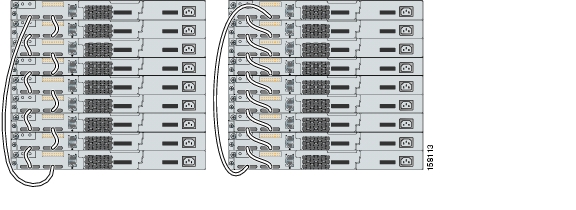
Side-By-Side Stacking
In this example, eight switches are stacked side-by-side with redundant connections by using 0.5- and 3-meter StackWise cables.
In this example, nine switches are stacked side-by-side with redundant connections by using 0.5- and 3-meter StackWise cables.
Power On Sequence for Switch Stacks
Consider these guidelines before you power on the switches in a stack:
•
•
•
•
For more information on stack master elections, see the "Managing Switch Stacks" chapter in the switch software configuration guide.
6 Rack-Mounting
This section covers basic 19-inch rack-mounting and switch port connections. As an example, all the illustrations show the Catalyst 3750E-48 PoE switch. You can install and connect other Catalyst 3750-E switches as shown in these illustrations. For additional installation and cabling information, see the hardware installation guide on Cisco.com.
Equipment That You Supply
You need a Phillips screwdriver to rack-mount the switch. For connecting the StackWise cables, you need a ratcheting torque screwdriver capable of 5 lbf-in. (80 ozf-in.).
Before You Begin
Before installing the switch, verify that these guidelines are met:
•
–
–
•
•
•
•
•
•
•
•
Installation Warning Statements
This section includes the basic installation warning statements. Translations of these warning statements appear in the Regulatory Compliance and Safety Information for the Catalyst 3750-E and Catalyst 3560-E Switch document that shipped with the switch and is also available on Cisco.com.
Warning
Warning
Warning
Caution
Note
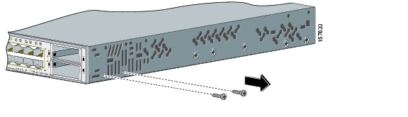
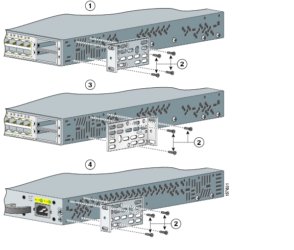
Before Attaching the Brackets
To install the switch in a rack, you must first remove the screws from the switch chassis so that the mounting brackets can be attached. For attachment at the front-mounting position, remove two Phillips truss-head screws from the switch side panels. For attachment at the mid-mounting position, remove one screw. For attachment at the rear-mounting position, remove two screws.
Attaching the Brackets
Use four number-8 Phillips flat-head screws to attach the long side of each bracket to the switch in one of three mounting positions.
Front-mounting position
Mid-mounting position
Number-8 Phillips flat-head screws
Rear-mounting position
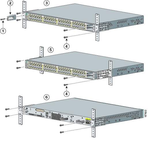
Rack-Mount the Switch
Use the four number-12 Phillips machine screws to attach the brackets to the rack. Use the black Phillips machine screw to attach the cable guide to the left or right bracket.
Black Phillips machine screw
Number-12 Phillips machine screws
Cable guide
Mid-mounting position
Front-mounting position
Rear-mounting position
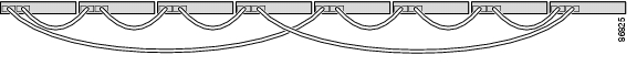
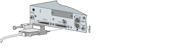
Connect the StackWise Cables
Use the window in the StackWise cable to align the connector correctly. Insert the cable into the StackWise port on the back of the switch. Using a ratcheting torque screwdriver, tighten the retainer screws to 5 lbf-in. (80 ozf-in.). Insert the other end of the cable into the connector of the other switch, and tighten the retainer screws to 5 lbf-in. (80 ozf-in.). Avoid overtightening the screws. Always use a Cisco-approved StackWise cable to connect the switches.
Caution
7 Connect to the Switch Ports
This section describes how to connect to the fixed switch ports and to the 10-Gigabit Ethernet module slots.
Connect to 10/100/1000 Ports
The 10/100/1000 Ethernet ports use standard RJ-45 connectors with Ethernet pinouts. The maximum cable length is 328 feet (100 meters). The 100BASE-TX and 1000BASE-T traffic requires Category 5, Category 5e, or Category 6 UTP cable. The 10BASE-T traffic can use Category 3 or Category 4 cable.
The autonegotiation feature is enabled by default on the switch. At this setting, the switch ports configure themselves to operate at the speed of attached devices. If the attached device does not support autonegotiation, you can explicitly set the switch port speed and the duplex parameters. To maximize performance, either let the ports autonegotiate both speed and duplex, or set the port speed and duplex parameters on both ends of the connection.
For simplified cabling, the automatic medium-dependent interface crossover (auto-MDIX) feature is enabled by default on the switch. With auto-MDIX enabled, the switch detects the required cable type for copper Ethernet connections and configures the interface accordingly. Therefore, you can use either a crossover or a straight-through cable for connections to a switch 10/100/1000 Ethernet port, regardless of the type of device on the other end of the connection.
See the switch software configuration guide or the switch command reference on Cisco.com for more information about enabling or disabling autonegotiation and auto-MDIX.
Connect to 10/100/1000 PoE Ports
The 10/100/1000 PoE ports have the same default settings and cabling requirements that are described in the previous section.
The PoE ports provide PoE support for devices compliant with IEEE 802.3af and also provide Cisco pre-standard PoE support for Cisco IP Phones and Cisco Aironet Access Points.
Each port can deliver up to 15.4 W of PoE. With the 1150-W power supply module, the Catalyst 3750E-48PS switch can deliver 15.4 W on all 48 ports. With the 750-W power supply module, the switches can deliver 15.4 W of PoE on any 24 of the 48 ports, or any combination of the ports can deliver an average of 7.7 W of PoE at the same time, up to a maximum switch power output of 370 W. On a per-port basis, you can control whether or not a PoE port automatically provides power when an IP phone or an access point is connected.
See the hardware installation guide on Cisco.com for more information about the switch power supply options.
Install and Connect to Devices in the 10-Gigabit Ethernet Slots
The switch 10-Gigabit Ethernet module slots are used for connections to other switches and routers. The module slots operate in full-duplex mode and use the hot-swappable Cisco X2 transceiver modules and the Cisco TwinGig Converter Module. The X2 transceiver modules have SC connectors to connect to multimode fiber (MMF) and single-mode fiber (SMF) cables. The Cisco converter modules have two SFP-module slots that convert the 10-Gigabit interface into a dual SFP interface.
When installing a transceiver module or the Cisco TwinGig Converter Module in the upper 10-Gigabit Ethernet module slot (slot 1), position the module face up. When using the lower module slot (slot 2), position the module face down.
Use only Cisco X2 transceiver modules, Cisco converter modules, and Cisco SFP modules with the switch. Each Cisco module has an internal serial EEPROM that is encoded with security information. This encoding provides a way for Cisco to identify and validate that the module meets the requirements for the switch.
Verify Port Connectivity
After you connect a device to the switch port, the port LED turns amber while the switch establishes a link. This process takes about 30 seconds. Then the LED turns green when the switch and the attached device have an established link. If the LED is off, the device might not be turned on, there might be a cable problem, or there might be a problem with the adapter installed in the device. See the "In Case of Difficulty" section for information about online assistance.
8 In Case of Difficulty
If you experience difficulty, help is available in this section and also on Cisco.com. This section includes Express Setup troubleshooting, how to reset the switch, how to access help online, and where to find more information.
Troubleshooting Express Setup
If Express Setup does not run, or if the Express Setup page does not appear in your browser:
Resetting the Switch
This section describes how to reset the switch by rerunning Express Setup. These are reasons why you might want to reset the switch:
•
•
•
Caution
To reset the switch:
•
The switch now behaves like an unconfigured switch. You can enter the switch IP information by using Express Setup as described in the "Running Express Setup" section.
Accessing Help Online
First look for a solution to your problem in the troubleshooting section of the hardware installation guide or the software configuration guide on Cisco.com. You can also access the Cisco Technical Support and Documentation website for a list of known hardware problems and extensive troubleshooting documentation.
For More Information
For more information about the switch, see these documents on Cisco.com:
•
•
•
•
•
•
•
•
•
•
•
•
9 Obtaining Documentation
Cisco documentation and additional literature are available on Cisco.com. Cisco also provides several ways to obtain technical assistance and other technical resources. These sections explain how to obtain technical information from Cisco Systems.
Cisco.com
You can access the most current Cisco documentation at this URL:
http://www.cisco.com/univercd/home/home.htm
You can access the Cisco website at this URL:
You can access international Cisco websites at this URL:
http://www.cisco.com/public/countries_languages.shtml
Documentation DVD
Cisco documentation and additional literature are available in a Documentation DVD package, which may have shipped with your product. The Documentation DVD is updated regularly and may be more current than printed documentation. The Documentation DVD package is available as a single unit.
Registered Cisco.com users (Cisco direct customers) can order a Cisco Documentation DVD (product number DOC-DOCDVD=) from the Ordering tool or Cisco Marketplace.
Cisco Ordering tool:
http://www.cisco.com/en/US/partner/ordering/
Cisco Marketplace:
http://www.cisco.com/go/marketplace/
Ordering Documentation
You can find instructions for ordering documentation at this URL:
http://www.cisco.com/univercd/cc/td/doc/es_inpck/pdi.htm
You can order Cisco documentation in these ways:
•
http://www.cisco.com/en/US/partner/ordering/
•
Documentation Feedback
You can send comments about technical documentation to bug-doc@cisco.com.
You can submit comments by using the response card (if present) behind the front cover of your document or by writing to the following address:
Cisco Systems
Attn: Customer Document Ordering
170 West Tasman Drive
San Jose, CA 95134-9883We appreciate your comments.
Cisco Product Security Overview
Cisco provides a free online Security Vulnerability Policy portal at this URL:
http://www.cisco.com/en/US/products/products_security_vulnerability_policy.html
From this site, you can perform these tasks:
•
•
•
A current list of security advisories and notices for Cisco products is available at this URL:
If you prefer to see advisories and notices as they are updated in real time, you can access a Product Security Incident Response Team Really Simple Syndication (PSIRT RSS) feed from this URL:
http://www.cisco.com/en/US/products/products_psirt_rss_feed.html
Reporting Security Problems in Cisco Products
Cisco is committed to delivering secure products. We test our products internally before we release them, and we strive to correct all vulnerabilities quickly. If you think that you might have identified a vulnerability in a Cisco product, contact PSIRT:
•
•
Tip
Never use a revoked or an expired encryption key. The correct public key to use in your correspondence with PSIRT is the one that has the most recent creation date in this public key server list:
http://pgp.mit.edu:11371/pks/lookup?search=psirt%40cisco.com&op=index&exact=onIn an emergency, you can also reach PSIRT by telephone:
•
•
10 Obtaining Technical Assistance
For all customers, partners, resellers, and distributors who hold valid Cisco service contracts, Cisco Technical Support provides 24-hour-a-day, award-winning technical assistance. The Cisco Technical Support Website on Cisco.com features extensive online support resources. In addition, Cisco Technical Assistance Center (TAC) engineers provide telephone support. If you do not hold a valid Cisco service contract, contact your reseller.
Cisco Technical Support Website
The Cisco Technical Support Website provides online documents and tools for troubleshooting and resolving technical issues with Cisco products and technologies. The website is available 24 hours a day, 365 days a year, at this URL:
http://www.cisco.com/techsupport
Access to all tools on the Cisco Technical Support Website requires a Cisco.com user ID and password. If you have a valid service contract but do not have a user ID or password, you can register at this URL:
http://tools.cisco.com/RPF/register/register.do
Note
Submitting a Service Request
Using the online TAC Service Request Tool is the fastest way to open S3 and S4 service requests. (S3 and S4 service requests are those in which your network is minimally impaired or for which you require product information.) After you describe your situation, the TAC Service Request Tool provides recommended solutions. If your issue is not resolved using the recommended resources, your service request is assigned to a Cisco TAC engineer. The TAC Service Request Tool is located at this URL:
http://www.cisco.com/techsupport/servicerequest
For S1 or S2 service requests or if you do not have Internet access, contact the Cisco TAC by telephone. (S1 or S2 service requests are those in which your production network is down or severely degraded.) Cisco TAC engineers are assigned immediately to S1 and S2 service requests to help keep your business operations running smoothly.
To open a service request by telephone, use one of the following numbers:
Asia-Pacific: +61 2 8446 7411 (Australia: 1 800 805 227)
EMEA: +32 2 704 55 55
USA: 1 800 553-2447For a complete list of Cisco TAC contacts, go to this URL:
http://www.cisco.com/techsupport/contacts
Definitions of Service Request Severity
To ensure that all service requests are reported in a standard format, Cisco has established severity definitions.
Severity 1 (S1)—Your network is "down," or there is a critical impact to your business operations. You and Cisco will commit all necessary resources around the clock to resolve the situation.
Severity 2 (S2)—Operation of an existing network is severely degraded, or significant aspects of your business operation are negatively affected by inadequate performance of Cisco products. You and Cisco will commit full-time resources during normal business hours to resolve the situation.
Severity 3 (S3)—Operational performance of your network is impaired, but most business operations remain functional. You and Cisco will commit resources during normal business hours to restore service to satisfactory levels.
Severity 4 (S4)—You require information or assistance with Cisco product capabilities, installation, or configuration. There is little or no effect on your business operations.
Obtaining Additional Publications and Information
Information about Cisco products, technologies, and network solutions is available from various online and printed sources.
•
http://www.cisco.com/go/marketplace/
•
•
•
http://www.cisco.com/en/US/learning/index.html
11 Cisco 90-Day Limited Hardware Warranty Terms
There are special terms applicable to your hardware warranty and various services that you can use during the warranty period. Your formal Warranty Statement, including the warranties and license agreements applicable to Cisco software, is available on Cisco.com. Follow these steps to access and download the Cisco Information Packet and your warranty and license agreements from Cisco.com.
1.
http://www.cisco.com/univercd/cc/td/doc/es_inpck/cetrans.htm
The Warranties and License Agreements page appears.
2.
a.
b.
c.
The Cisco Limited Warranty and Software License page from the Information Packet appears.
d.
Note
3.
a.
78-5236-01C0
b.
c.
The Cisco warranty page appears.
d.
You can also contact the Cisco service and support website for assistance:
http://www.cisco.com/public/Support_root.shtml.
Duration of Hardware Warranty
Ninety (90) days.
Replacement, Repair, or Refund Policy for Hardware
Cisco or its service center will use commercially reasonable efforts to ship a replacement part within ten (10) working days after receipt of a Return Materials Authorization (RMA) request. Actual delivery times can vary, depending on the customer location.
Cisco reserves the right to refund the purchase price as its exclusive warranty remedy.
To Receive a Return Materials Authorization (RMA) Number
Contact the company from whom you purchased the product. If you purchased the product directly from Cisco, contact your Cisco Sales and Service Representative.
Complete the information below, and keep it for reference:
Company product purchased from
Company telephone number
Product model number
Product serial number
Maintenance contract number
![]()
![]()
![]()
![]()
![]()
![]()
![]()
![]()
Posted: Mon Feb 12 09:38:48 PST 2007
All contents are Copyright © 1992--2007 Cisco Systems, Inc. All rights reserved.
Important Notices and Privacy Statement.