|
|

This chapter explains how to set up and modify the configuration of the Catalyst 3200 using a directly-attached console.
This chapter covers the following topics:
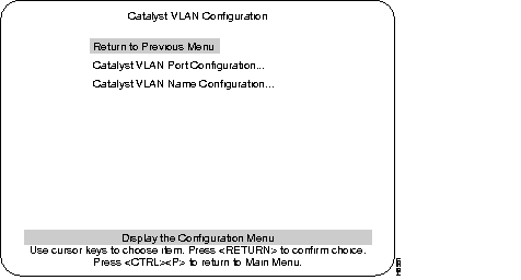
The Configuration menu enables you to view and set the Catalyst 3200 configuration parameters. The following section describes the Configuration menu and its sub-menus.
The following screen is displayed when the Configuration heading is selected from the Main menu.
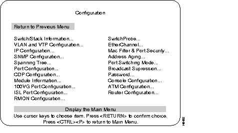
The following is a list of the headings in the Configuration menu. Detailed descriptions and views of the menu screens for these headings appear after this list.
Displays System Information screen for a switch or Stack.
Use the Switch Information screen to access software control of duplex functions.
Displays options for configuring VLAN. (Enhanced version only.)
Displays screen for changing IP addresses and subnet masks and for sending a PING.
Displays selections for setting attributes related to SNMP.
Displays selections for configuring Spanning-Tree Protocol.
Displays screen for changing port configuration.
Displays information regarding optional Expansion Modules.
Displays the screen for selecting a port to monitor.
Displays options for creating an EtherChannel. (Enhanced version only.)
Menu for configuring address filtering.
Displays a screen for setting a different aging time for the addresses in memory for the system and ports.
Displays the options available for setting the error handling modes for each port.
Displays a screen used to set up the control Broadcast packet traffic.
Displays screen for setting up and changing the password for access to the console.
Displays choices for setting-up console or Telnet sessions with the Catalyst 3200.
Use the Switch/Stack Information screen to view system information and to view or change the system name, location, contact, and time of day. To add or change the system name, location, contact or time of day, use the arrow keys to move the highlight to the selection and press the RETURN key. A prompt appears near the bottom of the screen for entering text for that selection. Pressing RETURN again enters that text.
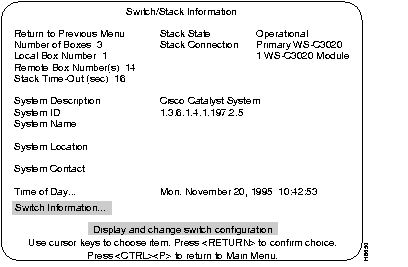
The number of boxes within this Stack.
The box number of the (local) Catalyst 3200 to which the console is connected. The local box is also the source of the information displayed in these screens.
The number of boxes that are in the Stack besides the one displaying this information.
If a box goes off-line, the length of time during which the Stack tries to re-establish communication with the box.
Default: 16 seconds
Displays whether or not the Stack is operational.
The type of unit connected to the Stack.
The following headings pertain to the information in the local Catalyst 3200 as part of a network system.
Name and model of this unit.
Unique identification code for this Catalyst 3200, assigned at the factory.
Any name you choose to assign to the switch (on a TCP/IP network, it could be the IP hostname).
Location of the switch.
Person to contact if questions should arise.
An internal clock is used to calculate total time of operation and time of day. To adjust the time, select this item, press RETURN, then enter the month, day, hour, or minute.
The following section describes the Switch Information menu from the Switch/Stack information menu.
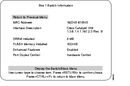
The MAC address of this unit.
The type of hardware and software and their version levels.
Number of megabytes of dynamic random-access memory in the Catalyst 3200. If a 4MB SIMM is installed, (standard configuration) the user sees "DRAM Installed 4MB." In the standard 4MB configuration, 6,000 addresses are allowed in each switch. With the 8MB SIMM installed, 10,000 addresses are allowed. The maximum number of addresses allowed is displayed under Main menu: "Statistics," then under "Switch Statistics" as Maximum Number of Stations.
Amount of flash memory installed on the Catalyst 3200. If a single flash is installed the number on the screen is 512KB. If two flashes are installed the number on the screen is 1024KB.
"Enabled" indicates that the optional Catalyst 3200 Enhanced feature set is enabled. To enable the feature set, call Cisco Support to obtain the key code. Highlight the field, enter the key (code), and press RETURN. If you purchased the Catalyst 3200 with the Enhanced feature set and you need to re-enter the code, the code is on the bottom of the unit.
Controls port duplex functions from hardware (switches) or from software.
In hardware mode, the duplexing is controlled by the duplex switches on the switch unit. In software mode, the duplexing is controlled at this menu. To switch between hardware and software mode, select the Port Duplex Control heading and press RETURN. The choice of Hardware or Software will appear. Select your choice and press RETURN. Selecting software will allow you to select the duplex mode for a specific port.
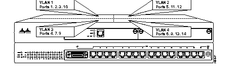
This section describes VLAN, the next selection on the Configuration menu. The optional VLAN and VTP feature is available on the Enhanced version of the Catalyst 3000 series (contact your Cisco sales representative for information). Using the VLAN feature, you can partition a single Catalyst 3200 into multiple VLANs, each containing its own set of ports. Packets are forwarded only between ports belonging to the same VLAN.
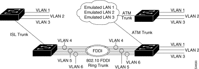
The benefit of VLAN partitioning is to restrict access from one segment to another, either for security purposes or to reduce intersegment traffic. Figure 7-1 illustrates a Catalyst with four VLANs.
Use VLAN Trunk Protocol to set up and manage VLANs across an entire management domain. When new VLANs are added to a Catalyst switch in a management domain, VTP can be used to automatically distribute the information to other trunks of all of the devices in the management domain. This allows VLAN naming consistency, and connectivity between all devices in the domain. The VTP is transmitted on all trunk connections, including Interswitch Link (ISL) and 802.10, and ATM LAN emulation (LANE).
On boot-up, a Catalyst switch sends out periodic requests for VTP configuration on all of its trunks until it receives a summary advertisement from a neighbor. It uses that summary advertisement to determine whether its currently stored configuration is obsolete and if it is, it requests all VTP information from the neighbor.
Figure 7-2 shows a diagram of the established VLANs, illustrating how VTP can traverse trunk connections using the ISL and 802.10 protocols and ATM LAN emulation (LANE).
The Catalyst switch transmits VTP frames on its trunk ports, advertising its management domain name, configuration revision number, and VLAN information that it has learned. Other Catalyst switches in the domain use these advertisements to learn about any new VLANs that are configured in the transmitting switch. This process of advertising and learning allows a new VLAN to be created and configured on only one switch in the management domain. This information is then learned automatically by all of the other devices in the domain.
A Catalyst switch can operate in three different VTP modes: Server, Client, or Transparent.
By using no-domain mode, VTP can operate with minimal configuration procedures. When a Catalyst switch is booted for the first time (and when it is rebooted after an NV RAM reset), it comes up in no-domain mode. The no-domain mode means there is no domain name configured into the box. While in no-domain mode, a switch will not attempt to advertise its own current configuration. If and when it receives an advertisement from any neighbor on any trunk, it will immediately accept the management domain name from the neighbor's advertisement as its own. After receiving all of the neighbor's configuration data, it will begin advertising this data regularly (after a reboot) on all of its trunks.
Use VTP transparent mode to have a Catalyst switch not participate in VTP and yet not have it cut off VTP configuration from propagating beyond it. In transparent mode, VTP packets received on one trunk are automatically propagated unchanged to all other trunks on the device but are ignored on the device itself.
 | Caution VTP packets circumvent spanning tree on the Catalyst switches. Transparent mode may cause loops on trunk ports. |
A checksum is calculated using an arbitrary security value that is appended to the front end and the back end of the data in a VTP configuration. Whenever a VTP device has received all of the parts of the VTP configuration, it recalculates the checksum using it's own security value derived from the password that has been configured locally. The device will not accept the new configuration if the checksums do not match.
On all Cisco VTP devices, the default initial configuration of the security value is all zeroes. Therefore, VTP devices will always accept one another's VLAN configurations as long as none of the security values on any of the devices have been modified. In order to make use of the security feature, a password needs to be set. The password must be the same for the management domain on all devices in the domain. Neither the password nor the security value itself is ever advertised over the network.
By default, the management domain is set to nonsecure mode, without a password. Adding a password sets the management domain to secure mode. The same password must be configured on each Catalyst switch in the management domain when in secure mode.
| Caution If a passwords are set, a management domain does not function properly if the same management domain password is not assigned to each Catalyst switch in the domain. |
ISL trunks multiplex packets from different VLANs by way of their ISL VLAN number in the ISL packet header. The ISL VLAN number is synonymous with the VTP VLAN ID. Packets received on non-transit VLANs on ISL links on VLANS that are not local transit VLANS on the switch, will be dropped.
LANE VLANs are identified by their 32 character name, which is synonymous with the VTP VLAN name. For this reason, VTP VLAN names are unique within an administrative domain. The Catalyst switch domain name has been expanded from 16 characters to 32 in order to match the size of the VTP/LANE VLAN name.
VLANs allow ports to be grouped so that traffic is confined to members of that group only. The group can contain the same or different switches. This feature restricts broadcast, unicast, and multicast traffic (flooding) to ports only included in a certain VLAN. VLANs can be set for an entire management domain from any VTP server device.
Setting up VLANs for a management domain requires two tasks, as follows:
Use the VTP VLAN Configuration menu to configure the following parameters for a VLAN in the management domain:
VTP Configuration screens consist of a main VLAN and VTP configuration menu. This menu allows access to:
VLAN and VTP Configuration menu: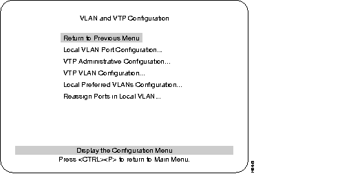
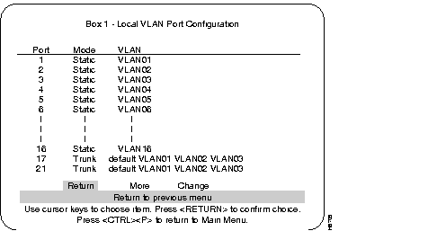
Local VLAN Port Configuration menu:
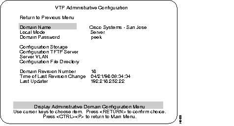
VTP Administrative Configuration menu:
The following sections describe the terms used in the VTP Administrative Configuration menu.
The name of the administrative domain the device is participating in (accepting updates from, and propagating configuration changes to).
Server, Client, or Transparent:
Password of up to 64 characters common to all devices in the administrative domain. A configuration will not pass between two devices with different passwords even if they are configured with the same administrative domain name.
NV Ram or TFTP server. This parameter is not configurable in Release 2.0.
TFTP server on which configuration storage file is located. This parameter is not configurable in Release 2.0.
VLAN where the TFTP server containing the configuration storage file is located. This parameter is not configurable in Release 2.0.
Directory on TFTP server on which configuration storage file is located. This parameter is not configurable in Release 2.0.
The revision number of the current configuration database implemented on this device.
The time the revision of the current configuration database implement on this device was created.
The IP address of the server where the revision of the current configuration database implemented on this device was created.
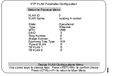
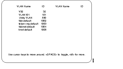
The following menu, VTP VLAN Configuration, is accessed from the VLAN and VTP Configuration menu. When the switch is in the Server mode, the menu displayed below is presented. The line after the VLAN Name parameters will read "Return More Change... Add... Delete."
When the switch is in the Client mode, that line will read "Return More Examine..." (the Client mode menu and explanation are presented after the Server mode menu).
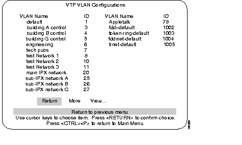
The Server mode VTP VLAN Configurations menu:
Selecting Add or Change at the VLAN Configurations menu presents the following statement: "Enter VLAN ID for the VLAN to be added (or changed)." Entering a VLAN ID and pressing RETURN presents the following menu. This menu is used for the configuration of an individual VLAN.
The Server version of the VTP VLAN Configuration menu: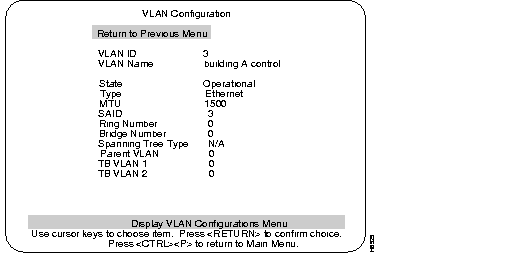
The numeric VTP ID, which is synonymous with the VLAN's ISL ID associated with the VLANs packets on ISL trunks. The allowable range is from 1 to 1005.
The ASCII name associated with the VLAN, which is synonymous with the VLAN's ELAN name on LANE trunks. Up to 32 characters are allowed.
VLANs in Operational state are functional. VLANs do not pass packets when Suspended.
VLAN type: Ethernet, FDDI, Token Ring, FDDI-net, and Token Ring-net.
The maximum transmission unit of the VLAN.
The SAID associated with the VLAN, which is the same as the VLAN's ID on FDDI trunks.
The ring number of the VLAN. (Only settable for FDDI and Token Ring VLANs.)
The bridge number of the VLAN. (Only settable for FDDI-net and Token Ring-net VLANs.)
The spanning tree type of the VLAN: IEEE 802.1 or IBM. (Only settable for FDDI-net and Token Ring-net VLANs.)
The VLAN ID of the parent ring associated with the VLAN. (Only settable for FDDI and Token Ring VLANs.)
The VLAN ID of VLAN(s) which are translationally bridged to this VLAN.
When the switch is in the Client mode the following menu is displayed when selected from the VLAN/VTP Configuration menu.
The Client version of the VLAN Configurations menu from the VLAN/VTP Configurations menu:
Selecting Examine... presents the line: "Enter VLAN ID for the VLAN to be examined." Entering a VLAN ID and pressing RETURN presents a menu with a description of that VLAN.
The VLAN Configuration menu from the VLAN Configurations menu:
The explanations of the terms in the Client version of the VLAN Configuration menu appear in the previous section, "Server Mode VLAN Configurations Menu."
This menu shows all of the VLANs in the system which currently transit the Stack (select More to scroll through multi-page lists). There is a maximum of 64 Preferred VLANS. VLANS denoted by an asterisks are VLANs selected as Preferred VLANs. VLANs in this display that are not denoted with asterisks are VLANs that were automatically selected for transit because they were the lowest-numbered Ethernet VLANs in the global VTP configuration.
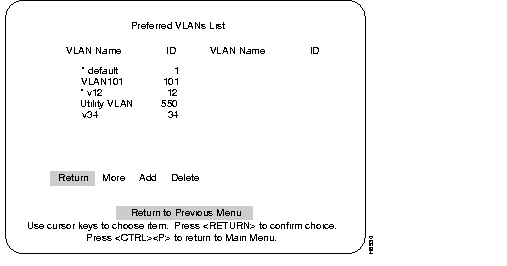
Preferred VLANs menu:
If Delete is selected, a prompt for a VLAN ID is displayed. Entering an ID and pressing RETURN will delete the selected VLAN from the Preferred VLAN list.
Selecting Add presents the next menu, the Preferred VLANs List menu, which is discussed in the next section.
Preferred VLANs List menu:
This list shows all currently non-preferred Ethernet VLANs in the global VTP configuration. Use the following steps to enter VLANs into the preferred list.
Step 1 Use the letter M key to page through a multi-page list.
Step 2 Use the ARROW keys to highlight and choose VLAN names.
Step 3 Press the SPACE key to toggle an asterisk on and off at the selected VLAN name (there is a limit of 64 VLANs that can be added to a preferred list).
When the RETURN key is pressed, VLANs with the asterisk toggled on are added to the preferred list.
Select this menu from the Configuration menu. Use this menu to view or change the IP configuration information.
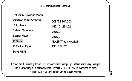
Displays the current IP address. To change it, highlight the selection and press RETURN.
Default: 0.0.0.0
Displays current gateway address. The default is the IP address of the gateway or router through which information must pass to get to the NMS application.
Default: 0.0.0.0
Displays the current subnet mask.
Default: 0.0.0.0
Select choices of IP Disabled, BootP When Needed or BootP Always by highlighting IP State and pressing RETURN, then highlighting one of the choices and pressing RETURN.
Default: BootP when Needed
Display type of Ethernet packet being presented.
Prompts for entering an IP address, then sends a PING to that address.
When a VLAN is IP-disabled, it does not process any IP or ARP packets it receives. This means that no SNMP, Ping, Telnet, or ARP Packets will be responded to when received.
In this state, IP is enabled for the VLAN and will function immediately if a non-zero IP address has been stored in NVRAM when the Catalyst 3200 initializes. In each VLAN that an IP address of 0.0.0.0 and a state of BootP When Needed are stored in NVRAM on boot (or NVRAM is not initialized on boot), the Catalyst will broadcast BootP requests in an attempt to determine its own IP address. Until it receives a reply, this is the only IP function the Catalyst will support (in the VLAN).
BootP When Needed is the factory-set default. A Catalyst for which NVRAM is not initialized (for instance, a new Catalyst out of the box or on a bootup after NVRAM is cleared), or one whose NVRAM is corrupted and unreadable, will therefore always attempt to use BootP the first time.
In this state, IP is enabled for the VLAN but will not function fully on boot until a BootP reply has been received. If a non-zero IP address is stored in NVRAM for a given VLAN in this state when booted, it is cleared to 0.0.0.0 since it would never be used.
When using BootP to determine its IP address, the Catalyst repeats BootP requests at regular intervals, beginning at 1 second each and eventually decreasing to every 5 minutes over time until it receives a valid reply. If the IP display for the VLAN is accessed from the console (or via Telnet from another VLAN) during that time, the Catalyst may cease using BootP if the parameters are set (on display exit) in such a way that BootP would no longer be necessary. For instance, if the IP state is switched from BootP Always to IP-disabled or if a non-zero IP address is specified in any IP state.
Once the Catalyst has ceased sending BootP requests on a VLAN, it does not restart sending requests on that VLAN for any reason other than an entire Catalyst reset. It also ceases to recognize BootP responses on that VLAN.
Besides the IP address, several other parameters in a BootP response are also recognized and recorded in NVRAM, when received in the same response:
One other parameter, the TFTP VLAN, is inferred whenever a TFTP Bootfile name is present in the BootP response. That is, if the Catalyst receives a BootP response that specifies a TFTP Bootfile name, the Catalyst automatically records the VLAN on which the response was received as the TFTP VLAN number. Therefore, the bootfile name should not be specified on a VLAN from which the TFTP server cannot be accessed, either directly or through the VLANs default gateway (if one exists). More information on TFTP is available under the section "TFTP" within this chapter.
The next selection of the Configuration Menu is the SNMP Configuration menu.
Screen displays and explanations of this menu and its sub-menus are presented in Chapter 9, "Console Configuration."
The next section describes spanning tree and the spanning tree menus from the Configuration menu.
The Spanning Tree Protocol (STP) is a bridge-to-bridge link management protocol that provides path redundancy while preventing undesirable loops. To provide path redundancy, the Spanning Tree Protocol defines a tree that spans all switches and bridges in the extended network; if one of the network segments in the tree becomes inaccessible, the spanning tree reconfigures itself to re-establish the links.
To prevent loops, the spanning tree selects one port as the designated path to the root, assigning it the Forwarding (or active) state. Ports that also have paths leading to the root will be assigned to the Blocking (or standby) state. Any remaining ports will be assigned to the Forwarding state.
A port in the Blocking state will not forward a received packet and, except for VTP and CDP packets, will not transmit a packet.
Select the Spanning Tree menu for the VLAN you wish to view, from the Configuration menu. Use the Spanning Tree menu to specify whether the VLAN is participating in spanning tree and, if so, to configure spanning tree bridge and port parameters.
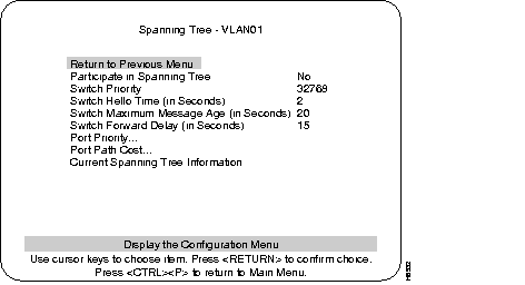
Select Yes or No by moving the highlight to the Participate in Spanning Tree heading and press RETURN. Then move the highlight to Yes or No and press RETURN. If you select No, the remaining values on the menu will be saved, but will have no effect. Selecting Yes will enable spanning tree for this VLAN upon exiting this screen.
Default: Yes
Enter a priority value for this bridge (switch). The bridge with the lowest priority value in a spanning tree becomes the root. This is also known as the bridge ID. The bridge ID consists of the combination of the bridge priority field and the bridge MAC address.
(To change individual Port Priorities, select Port Priority Menu.)
Range: 0-65535
Default: 32768
Enter a time to determine how often configuration messages are sent when this switch is root. The minimum value may not be less than 1. The maximum may not be more than the lower of 10 or Switch Maximum Message Age/2 - 1. The upper range limit that appears reflects the value currently selected for Switch Maximum Message Age.
Default: 2
Enter the maximum message age for configuration messages when this switch is root. The minimum value may not be less than the higher of 6 or (2 x (Switch Hello Time + 1)). The maximum may not be more than the lower of 40 or (2 x (Switch Forward Delay - 1)). The range limits that appear reflect the values currently selected for Switch Hello Time and Switch Forward Delay.
Default: 20
Enter the time the switch waits between transitions from listening to learning, and from learning to forwarding. The minimum may not be less than the larger of 4 or (2 x (Switch Maximum Message Age/2 +1)). The maximum may not be higher than 30. The lower range limit that appears reflects the value currently selected for Switch Maximum Age.
Default: 15
Displays a list of the port priorities of user selectable values. For more information on this menu, see the following section, Port Priority Screen.
Displays a list of port path costs of user selectable values. For more information on this menu, see the following section, Port Path Cost Menu
This selection displays the current status of spanning tree for this bridge. The Current Spanning Tree menu is presented if this heading is selected and if spanning tree is enabled ("Yes" is selected under "Participate in Spanning Tree" prompt).
When the spanning tree is turned off--that is, you have selected "No" for the "Participate in Spanning Tree" prompt--this menu cannot be selected.
To set up the Catalyst 3200 to use the Spanning Tree Protocol, you may assign a port priority and a port path cost value (other than the default value) to each VLAN on a trunk. Different values can be set for each VLAN on a trunk. Refer to the following sections for the appropriate console menus and descriptions of assigning port priority and port path cost.
Port priority and port path cost are used in conjunction with each other to try to even out the VLANs over the ATM trunks. Spreading the VLANs evenly over all of the available ATM trunks may increase the efficiency of the VLANs.
View the Port Priority Menu to set up spanning tree priorities for each port.
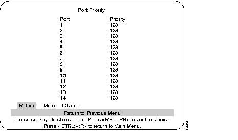
The number of the port.
If two ports to the same LAN have the same path cost, the spanning tree device selects the one with the highest priority (lowest value). To block traffic on a particular segment, assign it a lower port priority (higher value).
Select the port whose priority value you want to change, highlight "Change" and then press the RETURN key, enter the port number, then enter the new value. The port with the lowest number has the highest priority. New values take effect when you return to the previous menu.
Range: 0-255. (Default: 128)
To view more ports in the table.
To change or add values to specific ports.
Use the Port Path Cost Menu to view and change the spanning tree path cost associated with each port. Spanning tree uses port path costs to determine which port to select as a forwarding port. The path cost indicates the relative speed of the segment: The higher the speed of the segment, the lower the path cost. Switches and bridges in the network attempt to determine the path to the route with the lowest path cost.
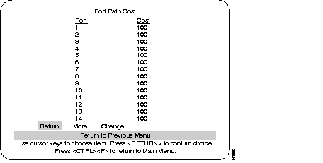
Select the port whose cost you want to change, press RETURN.
After selecting the port, enter a new value. When the spanning tree reconfigures itself, it selects forwarding ports based on the port cost. Therefore, assign lower numbers to ports attached to faster media (such as Full-Duplex Ethernet, Fast Ethernet or EtherChannel), and higher numbers to ports attached to lower-bandwidth media, such as Half-Duplex Ethernet. New values take effect when exiting this screen by choosing Return to Previous Menu.
IEEE 802.1D recommends that you assign path costs using the following formula:
Path cost = 1000/LAN speed in Mbps
Range: 0-65535.
Default: 10Mbsec Ethernet - 100
100Mbsec Ethernet - 10
155Mbsec ATM - 6
To change or add values to specific ports.
Use the Current Spanning Tree Information screen to view a summary of all spanning tree information for each port; the information is updated every second. You cannot change any information on this screen. When the spanning tree is turned off--that is, you have selected No for the Participate in Spanning Tree prompt--this menu cannot be selected.
The following sections describe the titles used on this screen. All of the terms across the heading of this screen are explained first and then the heading above each column is explained.
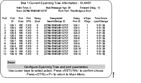
The Hello Time, in seconds, advertised by the root and used by all bridges and switches in the active topology of the spanning tree network.
The Maximum Message Age, in seconds, advertised by the root and used by all bridges and switches in the spanning tree network.
The Forward Delay Time, in seconds, advertised by the root and used by all bridges and switches in the spanning tree network.
The bridge ID of the switch in the spanning tree that this switch has accepted as the root device.
The number of the port on this switch that is closest to the root. This switch communicates with the root through this port. If this switch is the root, "This Bridge is Root" is displayed.
The following describes the information in each column.
The number of the port that this line of information pertains to. For a unit within a Stack, the number will be the box number of that switch, followed by a comma, and then the port number of that switch.
The port ID, used to determine the role of the port in the spanning tree. The port ID is expressed in the form <port priority>.<port number>. All ports in an EtherChannel have the same ID number.
The Port Path Cost for each port on the switch. The Port Path Cost helps determine the role of the port in the spanning tree network.
Current state of this port within the spanning tree: DSB (disabled), BLK (blocked),
LSN (listening), LRN (learning), or FWD (forwarding). The rules that define the state of the port are as follows:
The cost for a packet to travel from this port to the root in the current spanning tree configuration. The slower the media, the higher the cost.
Priority and MAC address of the device through which this port has determined it must communicate with the root of the spanning tree.
Port on the designated device through which this switch will communicate with the root of the spanning tree. This information is useful if the Catalyst 3200 is the designated switch on one or more network segments.
Number of topology changes, which is the number of times the port has entered the Forwarding state plus the number of times the port has made the transition from Forwarding to Blocking. The counter is reset when the switch is reset or the spanning tree is turned on, whichever is most recent.
The time since the last time the port entered the Forwarding state or made the transition from Forwarding to Blocking.
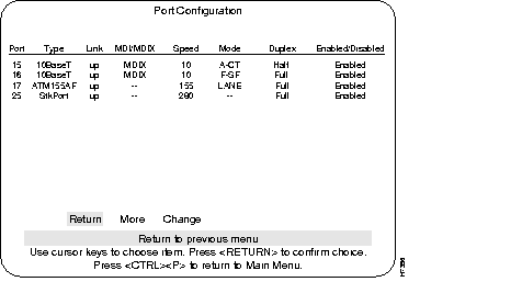
Use the Port Configuration Menu to enable or disable a port or change the port's duplex mode setting. This menu also reports other port status information.
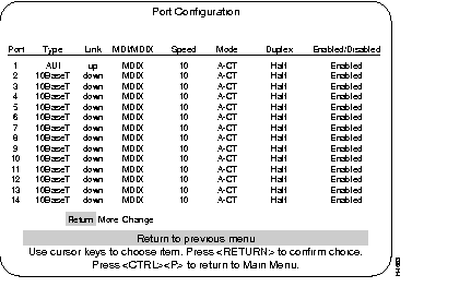
The port number.
Type of interface associated with this port
Whether a valid link status signal is associated with the port. "Up" means a device is connected to the port, "down" means that a device is not connected.
The MDI setting for 10BaseT ports.
The Ethernet speed for that port.
Shows error handling mode, such as Cut-Through or Store and Forward.
Shows the current duplex communication mode for this port. To change the duplex mode, you can either change the hardware Duplex DIP switch settings or you can change the duplex mode using software and the Port Configuration menu (software takes precedence).
Step 1 Select Change to select a port.
Step 2 Select duplex to select the duplex mode.
Operational status of ports. Toggle between enabled and disabled by selecting the port and pressing RETURN. The new status takes effect immediately.
Default: Enabled
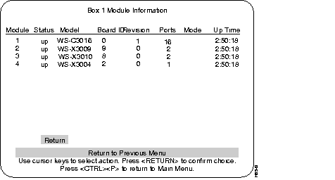
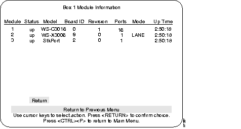
This menu provides information on any expansion modules that were installed. The Catalyst 3200 is listed as the first module.
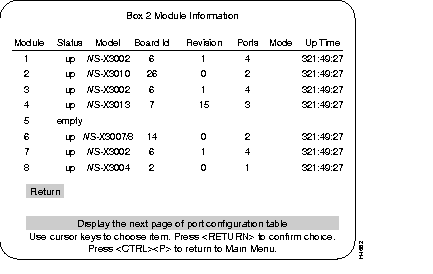
Lists whether the module slot is populated and if so, if it is enabled (up/down).
Lists the type of module.
Lists the revision level of the module.
Lists how many ports are on the module.
Lists how long the module has been active.
The screen displays and explanations of this menu and its sub-menus are presented in Chapter 9, "Monitoring Port Activity with Application Software."
The following section is a description of EtherChannel and how it is used with the Catalyst 3200.
Step 1 From the Configuration menu, select the Module Information sub-menu and press RETURN. The Module Information screen is displayed. Verify that "WS-X3009" or "WS-X3010" is displayed and that the status fields associated with it are similar to the example screen shown below (except for revision level).
The value in the Revision field may vary with subsequent hardware updates.
Step 2 Return to the Configuration menu and choose ISL Port Configuration. From the ISL Port Configuration menu, select a port to display ISL information about that port (see example in the following menu, ISL Port Configuration).
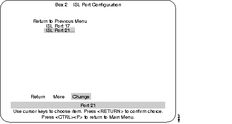
Step 3 In the selected ISL Port menu (see menu below) check or change ISL port information:
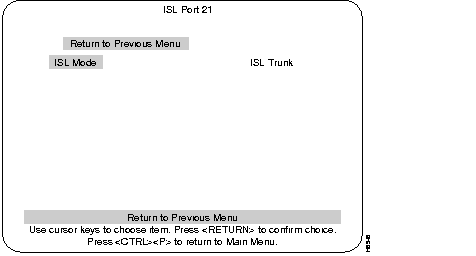
Step 4 To change the present mode of the ISL port, highlight the ISL Mode heading and press RETURN. New headings appear at the lower portion of the screen (see the following screen).
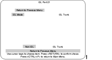
Step 5 Using the left or right arrow keys, move the "highlight" over either Non-ISL or ISL Trunk and press RETURN for your selection (or press ESCAPE to cancel the selection). The heading at the upper right of the screen will toggle from Non-ISL to ISL Trunk depending upon your selection. That selection is the mode for that port.
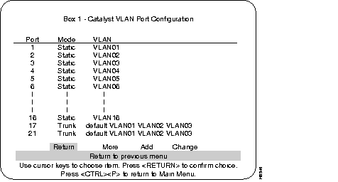
Step 6 To check the status of ISL ports in relation to VLAN configuration, return to the Configuration menu and select VLAN Configuration and then select VLAN Port Configuration (see the following menus).
Step 7 The ports that were configured to ISL at the ISL Port Configuration menu will show on the VLAN Configuration menu as "Trunk" ports. Non-ISL ports (in that VLAN) will show as Static.
Step 8 If that VLAN does have ISL Trunk ports listed, all of the VLANs that are carried by that trunk will be listed to the right of that trunk port number (see example in the following menu, VLAN Port Configuration).
Step 9 To check a port's statistics, return to the Configuration menu, choose the Main menu and then choose the Statistics menu. Display the message log information for the switch. Pay special attention to ISL type messages recorded in the log. If possible, screen-capture the message log or make note of ISL-related messages for future references.
Step 10 Check your network health monitoring equipment (if available) to ensure that the network is running cleanly. Check attached network devices for any obvious signs that the flow of data is being impeded.
Step 11 After checking any monitoring equipment, log back into the console, go to the Statistics menu, and display the message log. Pay special attention to ISL specific messages. Compare the ISL specific messages present in the log to the messages previously recorded. If needed, consult with Cisco support for an explanation of the different messages and their importance. Select RETURN to exit the display and return to the Statistics menu. If necessary, repeat this for each switch that contains an ISL configuration.
Periodically check the health of the network and the message log on each of the Catalyst switches involved. If you detect any irregularities, investigate them immediately and, if needed, contact Cisco support.
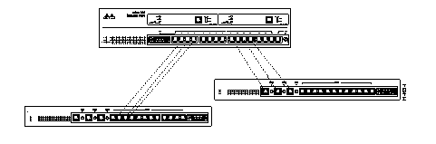
To improve interswitch bandwidth, you can create an EtherChannel by connecting two EtherChannel devices (see Figure 7-3) that have two to seven links. An EtherChannel provides bandwidth of from 20-80 Mbps in Half-Duplex mode, or from 40-160 Mbps in Full-Duplex mode. You can create an EtherChannel only between two Catalyst 3200 devices or between a Catalyst 3200 and a CiscoPro unit, and not between a Catalyst 3200 and a workstation.
The EtherChannel feature affects other Catalyst 3200 features in the following ways:
EtherChannel software learns addresses differently than regular ports, as follows:
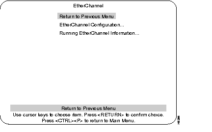
Use the EtherChannel Configuration menu to add, delete, and change EtherChannels. A description of creating an EtherChannel follows this menu.
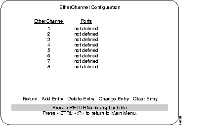
List of different EtherChannel setups.
The ports within that specific EtherChannel.
Prompts you to enter port numbers in the EtherChannel. Enter at least 2 ports, but no more than 7 ports, from lowest number to highest, separated by spaces. Don't use 10BaseT port 1 for EtherChannel.
Asks whether you want to remove the entry, then deletes the selected EtherChannel.
Prompts you to re-enter the port numbers in the selected EtherChannel, from lowest to highest, separated by spaces.
Deletes all EtherChannels.
To add an EtherChannel between two Catalyst 3000 series devices, determine which ports to use for the EtherChannel. Use at least 2 ports, but no more than 7 ports (port 1 is not recommended for EtherChannel use).
The Catalyst 3000 series switch treats the port with the lowest number as the primary port. For example, if an EtherChannel consists of ports 8,11, and 13, the primary port is 8. Broadcast, multicast, and unknown destination packets are forwarded first to the primary port in an EtherChannel. The primary ports of both EtherChannels must be connected to each other. For example, if an EtherChannel links ports 8, 11, and 13 of one device and ports 3,6,and 9 of another device, ports 8 and 3 must connect to each other.
Observe the following precautions and use the following steps to set up an EtherChannel:
Step 1 Disconnect the ports you want to add to the EtherChannel, or disable them using the Port Configuration menu.
Step 2 For one Catalyst, select the EtherChannel menu (shown later in this section), then choose Add Entry from the menu bar at the bottom on the screen.
Step 3 Enter the ports (port 1 is not recommended for EtherChannel use) for the EtherChannel column, separated by spaces.
Step 4 Choose Exit.
Step 5 Repeat steps 1-4 for the other Catalyst devices.
Step 6 Set the Address Aging Time to the same value for the Catalyst devices.
Step 7 If you disconnected the ports in the EtherChannel, reconnect them. If you disabled them using the Port Configuration menu, use the menu to re-enable them.
Use the Running EtherChannel Configuration menu to display the status of the EtherChannel.
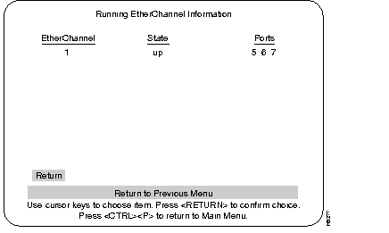
The number of the EtherChannel referring to the information displayed on the present screen.
Whether the specified EtherChannel is active or not.
What ports are in that EtherChannel.
The Address Filtering feature enables you to restrict certain users from communicating with other users. To do this, you can specify source and destination MAC-layer Ethernet addresses to be filtered at the source port. Ethernet addresses can be unicast, multicast, or broadcast.
The advantage of address filtering is increased access control and network segmentation. For example, suppose one port is connected to a server containing confidential information from the engineering workgroup. You can prevent access to the server by setting up filters for the addresses of connections from workgroups other than engineering. This is an example of two types of filters, "allowing a source address" (engineering) or "blocking a source address(es)" (other workgroups). Examples of different types of filters are allowing, forcing, or blocking packets from a source address, or allowing, forcing, or blocking packets to a destination address. A detailed explanation of filter types is in the section "Configure Filters Screen from the MAC Filter and Port Security Menu" in this chapter.
Observe the following guidelines when setting up address filters:
The following menus, in this Address Filtering section, are used to set up address filtering. More explanations of address filtering are presented when functions within these menus are described.
The MAC Filter and Port Security Screen:
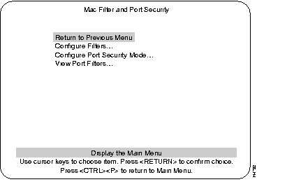
Used to establish specific filtering of addresses.
Establishes address security at specific ports.
Displays filtering set up for specific ports.
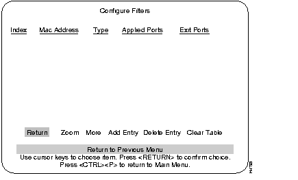
When the Add Entry is selected, a list of the available filter functions is displayed. Use the highlight to select a function. After you make a choice, the program prompts you for the necessary parameters.
There are four filter functions options:
The table displayed in the filter screen is updated whenever a filter is added.
For a stack configuration, you cannot enter more than one port on any remote box. You can, however, enter more than one port on the local box.
The purpose of this filter is to block all packets from a specific source address at the incoming port(s) you select. If you select this filter, the following parameter fields appear for you to enter data:
Please enter the MAC address (xx  xx  xx  xx  xx  xx)
Please enter the port(s) to apply this filter:
The purpose of this filter is to prevent certain port(s) from receiving any packets to a specific address. If you select this filter, the following parameter fields appear for you to enter data:
Please enter the MAC address (xx  xx  xx  xx  xx  xx)
Please enter the port(s) to apply this filter:
The purpose of this filter is to allow packets that have a specified source address to enter the specified filtered port(s), so it can send those packets only to specific port(s). If you select this filter, the following parameter fields appear for you to enter data:
Please enter the MAC address (xx  xx  xx  xx  xx  xx)
Please enter the port(s) where a matching packet is allowed to go:
Please enter the port(s) to apply this filter:
The purpose of this filter is to take packets with a specified address, on an incoming filtered port(s), and force those packets to specific outgoing ports. If you select this filter, the following parameter fields appear for you to enter data:
Please enter the MAC address (xx  xx  xx  xx  xx  xx)
Please enter the port(s) where a matching packet must go:
Please enter the port(s) to apply this filter:
The information in each column of the Configure Filters menu is described as follows:
The address to which the filter is applied.
The type is determined by the filter function selected. The type functions are:
The port(s) where this filter entry is applied for that specified MAC address.
The specified port(s) where a packet is allowed to go, or forced to go (for that specific MAC address).
The types of filter functions that would not have an exit port are:
The types of filter functions that would have an exit port are:
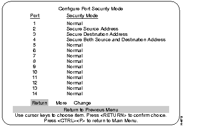
This mode establishes secure address levels for specific ports. Select this heading at the MAC Filter and Port Security screen.
There are four address security choices:
The following screen is an example of ports using the MAC address filters and port security.
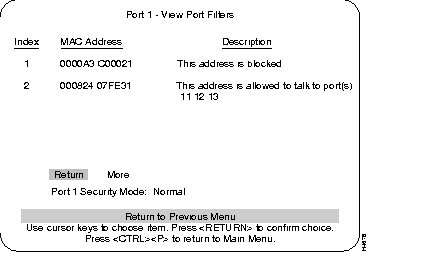
Numerical order of entries.
Filter Address
List of descriptions of security modes as assigned at Configure Port Security Mode menu:
Return to main menu.
Displays additional entries in the filter table if the table contains multiple pages.
The type of security mode applied to this port.
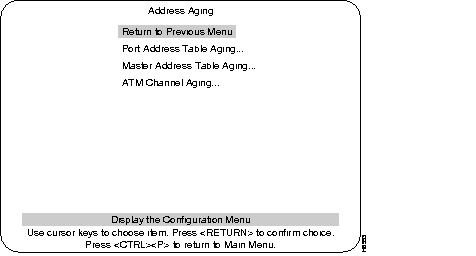
You can set the per-port aging value using the Address Aging menu. The following describes the types of address aging.
There are two types of aging:
There are two levels to set for the port and master aging tables:
Time Interval Aging is a time limit, in minutes, which will drop "older" addresses after the selected time.
Automatic On-Demand Aging stores addresses until reaching maximum capacity of the table, then deletes addresses, (in the following specific order) down to a selected percentage level and continues to cycle in the same manner.
More information on address aging and the address aging screens is presented in the following sections.
Address aging is accessed through the Address Aging heading from the Configuration Menu.
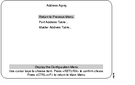
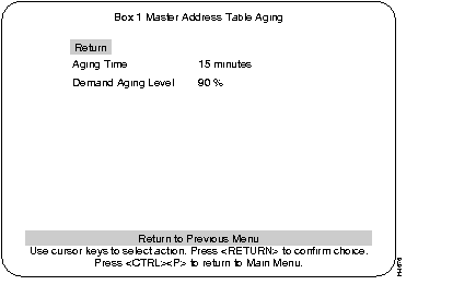
Highlighting this selection and pressing RETURN will display the Port Address Table Aging menu. Use this menu is to set each port on the Catalyst 3200 to the aging time, in minutes, and to the demand aging level percentage you want.
This screen shows the Master Aging Time and Demand Aging Level. An example of that selection is shown after the Port Address Table Aging screen.
The following displays a view of the Port and Master Address Table Aging screens and describes the information within them.
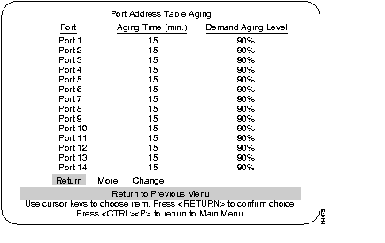
The port to which you want to assign an aging time.
A valid port aging time associated with the port. Addresses will be discarded after reaching the set time limit. The default setting for this parameter is 15 minutes. The maximum time for this value is 9999 minutes.
Sets a percentage threshold of address table capacity to ensure that the port's address table is populated only by the most frequently used addresses. Addresses are stored until reaching the maximum capacity of the table, then discarded in a specific order until the set percentage of table capacity is reached and then cycles in the same manner.
The Master Address Table Aging is the aging value of a set time, in minutes, and a set percentage level after which unused addresses are removed from its table. Addresses that are local to a port but did not fit in its address table ("orphans") will be removed from the master table and all port address tables after the master aging time, regardless of whether the address has been seen within that time period. This is to ensure that no unused address will remain in memory for an indefinite time.
Master Address Table Aging screen:
The Master Address Table Aging screen contains two main headings. (If there is a box number it is the number of the switch that this screen is referencing.)
Master table addresses will be discarded after reaching the set time limit. The default setting for this parameter is 15 minutes. The maximum time for this value is 9999 minutes.
This parameter works in the same way as Port Demand Aging Level, only using the system address table.
This screen shows the status of the packet switching modes available on the Catalyst 3200.
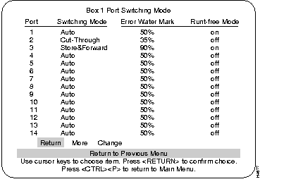
Displays three configurable modes of packet switching:
To change the mode, highlight "Change" and press RETURN. You are prompted to select mode, then the high water percentage (if Auto mode selected) and finally the setting for Runt-free mode.
At what percentage level of errors the Catalyst 3200 will switch from cut-through to store-and-forward mode (if Auto mode is selected for that port).
This mode is set to either on or off. If set to on, an incomplete packet (less than 64 bytes) will be discarded, and a runt packet error is logged and displayed under the Statistics menus. If set to off, runt packets will be forwarded through the switch.
As the name implies, this feature is to suppress broadcast packets. This function is set on a per-port basis at the Broadcast Suppression screen. If set to on (enable), that port is set to a percentage threshold level (Broadcast Water Mark) at which broadcast packets are suppressed (percentage is based on total traffic). If the broadcast level on a specific port exceeds the set threshold, all broadcasts originating from that port are blocked until the broadcast level drops below that mark.
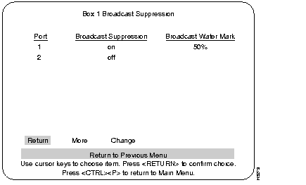
Displays whether broadcast suppression is enabled or disabled for that specific port.
A user-defined percentage level based on broadcast traffic compared to the total traffic on that port. If broadcast traffic exceeds this level, packets are suppressed until they fall below that level.
Use the following steps to confirm that the installation has been completed correctly.
Step 1 From the Configuration menu, select the Module Information sub-menu and press RETURN. The Module Information screen is displayed. Verify that "WS-X3006A" is displayed and that the status fields associated with it are similar to the following example screen (except for revision level).
Step 2 From the Configuration main menu, choose Port Configuration. From this menu display, choose "More" to display information for ports 17 and 21. Verify that the status fields associated with it are similar to the example screen shown below (except for MDI/MDIX).
Step 3 In the Port Configuration menu check the following headings to verify ATM port information:
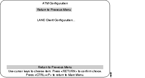
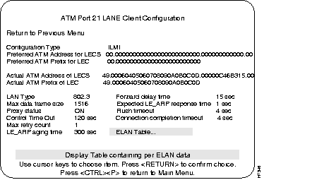
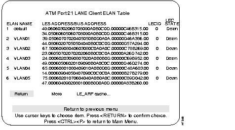
Step 4 From the Configuration menu, choose the "ATM Configuration" menu. From that menu, choose the "Lane Client Configuration" menu and enter the appropriate ATM port number. Verify the ATM address information in the ATM LANE Client Configuration menu that is displayed and then from that menu, select the ELAN Table sub-menu and verify information on configured ELANs.
Step 5 Return to the Main menu. Choose the Statistics menu. Display the message log information for the switch. Pay special attention to ATM type messages recorded in the log. If possible, screen capture the message log or make note of ATM related messages for future references.
Step 6 Clear the message log buffer using the Clear Logs command at the bottom of the message display log screen.
Step 7 If necessary, reconnect the Catalyst 3200 switches back into your network topology and channel the normal data flow back to them. If reconnecting the switches into your network, be sure that the link LEDs are lit for each of the connected 10BaseT ports.
Step 8 Check your network health monitoring equipment (if available) to ensure that the network is running cleanly. Check attached network devices for any obvious signs that the flow of data is being impeded.
Step 9 From each Catalyst 3200 switch containing ATM modules, log back into the console, go to the Statistics menu, and display the message log. Pay special attention to ATM-specific messages. Compare the ATM-specific messages present in the log to the messages previously recorded. If needed, consult with Cisco support for an explanation of the different messages and their importance. Select RETURN to exit the display and return to the Statistics menu. Repeat this for each switch.
Step 10 Verify the address tables on each of the Catalyst 3200s by viewing the Address Table option from the Statistics menu. Check each of the menus for the following information:
Periodically check the health of the network and the message log on each of the Catalyst 3200 switches involved. If any irregularities are seen, investigate them immediately and, if needed, contact Cisco support.
Configuration and statistical status menus for the Catalyst 3200 switch and the WS-X3006A ATM module are available through the Catalyst 3200's console port or by creating a Telnet session into the Catalyst 3200. For detailed information on creating Catalyst 3200 console and Telnet sessions, see Chapter 6, "Connecting a Console."
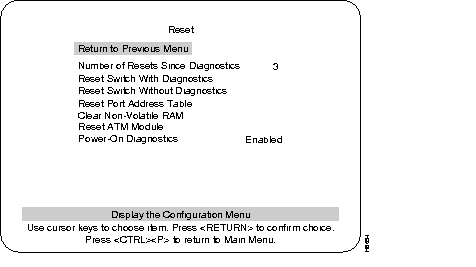
Use the Reset menu if you need to reset the ATM module.
The following menus (from the Configuration menu) are used to configure and to check the status of the ATM module. These menus are presented and described in subsequent sections.
This section describes how ATM LANE (Local Area Network Emulation) is used with the Catalyst 3200. The next section describes how to configure the Catalyst 3200 ATM module interface using LAN emulation clients for LAN emulation.
Setting up LECs (LAN Emulation Clients) allows the Catalyst 3200 series switch to operate in an ATM LAN environment containing Cisco 7000 or 4500 series routers with ATM Interface Processors (AIP) connected to a LightStream 100 or 1010 ATM switch.
Cisco's implementation of LANE makes an ATM interface look like one or more Ethernet interfaces.
LANE is an ATM service defined by the ATM Forum specification "LAN Emulation over ATM," ATM_FORUM 94-0035. This service emulates the following LAN-specific characteristics:
LANE service provides connectivity between ATM-attached devices and LAN-attached devices. This includes connectivity between ATM-attached stations and LAN-attached stations as well as connectivity between LAN-attached stations across an ATM network.
Because LANE connectivity is defined at the MAC layer, upper protocol layer functions of LAN applications can continue unchanged when the devices join emulated LANs. This feature protects corporate investments in legacy LAN applications.
An ATM network can support multiple independent emulated LANs. Membership of an end system in any of the emulated LANs is independent of the physical location of the end system. The end systems can move easily from one emulated LAN to another, independent of whether or not the hardware moves.
This release of LANE is supported on Catalyst 3200 series switches containing ATM modules and on Cisco 7000/4500 routers with AIPs installed; it requires an ATM switch that supports UNI 3.0 and point-to-multipoint signaling, for example the Cisco LightStream 100/1010 ATM switches.
Up to 256 emulated LANs can be set up in an ATM switch cloud. A Catalyst 3200 ATM module can participate in up to 64 of these emulated LANs.
LANE is defined on a client-server LAN model, as follows:
A LANE client emulates a LAN interface to higher layer protocols and applications. It forwards data to other LANE components and performs LANE address resolution functions.
Each LANE client is a member of only one emulated LAN. However, a router or a Catalyst 3200 ATM module can include LANE clients for multiple emulated LANs: one LANE client for each emulated LAN of which it is a member.
If a router has clients for multiple emulated LANs, the router can route traffic between the emulated LANs.
The LANE server for an emulated LAN is the control center. It provides joining, address resolution, and address registration services to the LANE clients in that emulated LAN. Clients can register destination unicast and multicast MAC addresses with the LANE server. The LANE server also handles LANE ARP (LE ARP) requests and responses.
The current Cisco implementation has a limit of one LANE server per emulated LAN.
The LANE broadcast-and-unknown server sequences and distributes multicast and broadcast packets and handles unicast flooding.
One combined LANE server and broadcast-and-unknown server is required per emulated LAN.
The LANE configuration server contains the database that determines which emulated LAN a device belongs to (each configuration server can have a different named database). Each LANE client consults the LANE configuration server just once, when it joins an emulated LAN, to determine which emulated LAN it should join. The LANE configuration server returns the ATM address of the LANE server for that emulated LAN.
One LANE configuration server is required per ATM LANE switch cloud.
The LANE configuration server's database can have the following four types of entries:
{Emulated LAN name, ATM address of LANE server} pairs
{LANE client MAC address, emulated LAN name} pairs
{LANE client ATM template, emulated LAN name} pairs
Default emulated LAN name
The Catalyst 3200 ATM module currently only supports the LANE client function. The Cisco 7000 router with AIP can supply all LANE functions.
Communication among LANE components is ordinarily handled by several types of switched virtual circuits (SVCs). Some SVCs are unidirectional; others are bidirectional. Some are point-to-point and others are point-to-multipoint. Figure 7-4 illustrates the various types of SVCs. In this figure, LECS stands for the LANE configuration server, and BUS stands for the LANE broadcast-and-unknown server.
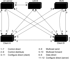
The following section describes various processes that occur, starting with a client requesting to join an emulated LAN.
The process illustrated in Figure 7-4 normally occurs after a LANE client has been enabled on the ATM module in a Catalyst 3200 switch:
Client sets up a connection to the LANE configuration server to find the ATM address of the LANE server for its emulated LANE. See the bidirectional, point-to-point link, 1-7 in Figure 7-4).
A LANE client locates the LANE configuration server by using the following sources in the listed order:
Using the same VCC, the LANE configuration server returns the ATM address and the name of the LANE server for the client's emulated LAN.
The client sets up a connection to the LANE server for its emulated LAN (bidirectional point-to-point Control Direct VCC, link 1-7 in Figure 7-4) to exchange control traffic.
Once a Control Direct VCC is established between a LANE client and a LANE server, it remains up.
The server for the emulated LAN sets up a connection to the LANE configuration server to verify that the client is allowed to join the emulated LAN (bidirectional point-to-point Server Configure VCC, link 11-12 in Figure 7-4). The server's configuration request contains the client's MAC address, its ATM address, and the name of the emulated LAN. The LANE configuration server checks its database to determine whether the client can join that LAN; then it uses the same VCC to inform the server whether or not the client is allowed to join.
If allowed, the LANE server adds the LANE client to the unidirectional point-to-multipoint Control Distribute VCC (link 2-8 in Figure 7-4) and confirms the join over the bidirectional point-to-point Control Direct VCC (link 1-7 in Figure 7-4). If disallowed, the LANE server rejects the join over the bidirectional point-to-point Control Direct VCC (link 1-7 in Figure 7-4).
Sending LE ARP packets for the broadcast address returns the ATM address of the BUS. Then the client sets up the multicast send VCC (link 4-9 in Figure 7-4) and the BUS adds the client to the multicast forward VCC (link 5-10 in Figure 7-4) to and from the broadcast-and-unknown server.
As communication occurs on the emulated LAN, each client dynamically builds a local LANE ARP (LE ARP) table. A client's LE ARP table can also have static, preconfigured entries. The LE ARP table maps MAC addresses to ATM addresses.
When a client first joins an emulated LAN, its LE ARP table has no dynamic entries and the client has no information about destinations on or behind its emulated LAN. To learn about a destination when a packet is to be sent, the client begins the following process to find the ATM address corresponding to the known MAC address:
For unknown destinations, the client sends a packet to the broadcast-and-unknown server, which forwards the packet to all clients. The broadcast-and-unknown server floods the packet because the destination might be behind a bridge that has not yet learned this particular address.
When a LANE client has broadcast or multicast traffic, or unicast traffic with an unknown address to send, the following process occurs:
This VCC branches at each ATM switch. The switch forwards such packets to multiple outputs. (The switch does not examine the MAC addresses; it simply forwards all packets it receives.)
On a LAN, packets are addressed by the MAC-layer address of the destination and the source stations. To provide similar functionality for LANE, MAC-layer addressing must be supported. Every LANE client must have a MAC address. In addition, every LANE component (server, client, broadcast-and-unknown server, and configuration server) must have a unique ATM address.
In this release, all LANE clients on the same interface have different, automatically assigned MAC address. That MAC address is also used as the end-system identifier (ESI) part of the ATM address, as explained in the following section.
A LANE ATM address has the same syntax as an NSAP, but it is not a network-level address. It consists of the following:
The Catalyst 3200 ATM module uses ILMI registration to build its ATM address and to register this address with the ATM switch. To build its ATM address, the Catalyst 3200 obtains its ATM address prefix from the ATM switch. Then it combines the ATM address prefix with its own MAC address and the selector value of 0 (zero). Once the Catalyst ATM module has determined its ATM address, it uses ILMI registration to register this address with the ATM switch.
On the Catalyst 3200 series switch, a VLAN is a logical group of end stations, independent of physical location, with a common set of requirements. Currently, the Catalyst 3200 series switch supports a port-centric VLAN configuration. All end stations connected to ports belong to the same VLAN and are assigned to the same VLAN name. The VLAN name is only significant to the Catalyst 3200 series switch.
In typical LANE cases, one or more Catalyst 3200 series switches or Cisco 7000 routers are attached to a Cisco LightStream 100 ATM switch. The LightStream 100 switch provides connectivity to the broader ATM network switch cloud. The routers are configured to support one or more emulated LANs. One of the routers is configured to perform the LANE configuration server functions. A router is configured to perform the server function and the broadcast-and-unknown server function for each emulated LAN. (One router can perform the server and the broadcast-and-unknown server functions for several emulated LANs.) Routers and Catalyst 3200 series switches can act as a LANE client for one or more emulated LANs.
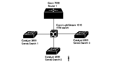
This section presents two scenarios using Cisco 7000 routers, Catalyst 3200 series switches and Cisco LightStream 100 workgroup ATM switch. Figure 7-5 and Figure 7-6, respectively, illustrate example layouts of single and multiple emulated LANs.
The physical layout and the physical components of an emulated network might not differ for the single and the multiple emulated LAN cases. The differences are in the software configuration for the number of emulated LANs and the assignment of LANE components to the different physical components.
In a single emulated LAN configuration, the LANE components might be assigned to a particular department in a company. The Manufacturing department is used for the following scenario:
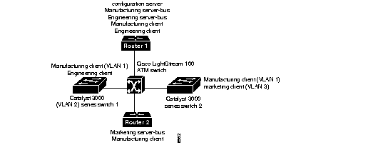
In a multiple LAN scenario, one ATM switch, two routers, and two Catalyst 3200 series switches are used, but multiple emulated LANs are configured. In the following example, three emulated LANs are configured on two routers and two Catalyst 3200 series switches for three different departments in a company.
The LANE components are assigned as follows:
Before you begin to configure LANE, you must decide whether you want to set up one or multiple emulated LANs and, if multiple, where the servers and clients will be located, and whether to restrict the clients that can belong to each emulated LAN. Once you have made those basic decisions, you can proceed to configure LANE.
Some of the tasks required to configure LANE are performed on a Cisco router or a LightStream switch. For information on how to perform these tasks, refer to the appropriate Cisco Router Products Configuration Guide and the appropriate Cisco LightStream User Guide. Only the tasks pertaining to configuring the Catalyst 3200 series switch are provided in the following sections.
You can configure some emulated LANs with unrestricted membership and some emulated LANs with restricted membership. You can also configure a default emulated LAN, which must have unrestricted membership.
To configure LANE, complete the following tasks:
The following items may need to be performed before configuring a LANE on the Catalyst 3200.
The following configuration notes describe the configuration of a LANE on a Catalyst 3200.
As a reference only, this section lists all of the console menus that pertain directly to the Catalyst 3200 ATM module.
This menu is selected from the ATM Configuration menu. Use this menu to check the configuration information of the LANE Client.
This menu is selected from the ATM LANE Client Configuration menu. This menu provides the LES/BUS addresses for each VLAN.
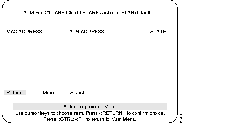
This menu is accessed from the ATM LANE Client ELAN Table menu. This menu provides information on the LE_ARP Cache for default ELAN.
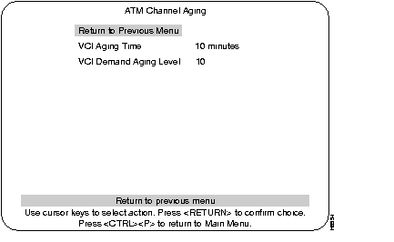
The ATM Channel Aging menu is used to age out less frequently used ATM channels. The concept of address aging and management is described in the Address Aging section. This menu is accessed from the Address Aging menu. At the Address Aging menu, select ATM Channel Aging and press RETURN.
Select this menu from the Address Aging menu. See the Address Aging section in this chapter for an explanation of the terms Aging Time and Demand Aging Levels.
The ATM Port Info/Statistics menu is used to access ATM Statistics and Board information menus. Access this menu from the Statistics menu.
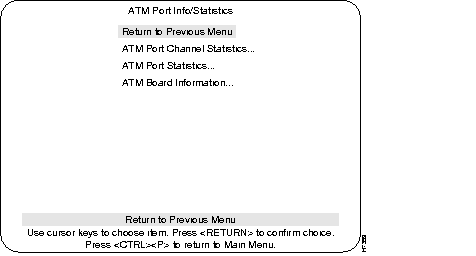
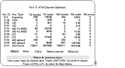
The ATM Port Channel Statistics menu lists the number of frames and bytes that were transmitted and received by the channels on the selected ATM port. The last column lists any receive errors.
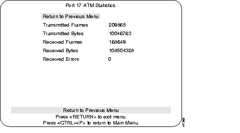
This menu lists the number of frames and bytes that have been transmitted and received per the selected ATM port (17 or 21). The last line displays the number of received errors for that port.
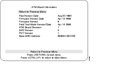
The ATM Board Information menu provides details about the selected ATM board.
Cisco Discovery Protocol is used with Cisco IOS software to establish communication between different models of Cisco equipment (such as with a Cisco Catalyst 3000 and a Cisco 7000 router).
|
|