|
|

This chapter provides a quick installation and setup procedure for a standalone switch.
 |
Note For detailed installation procedures on rack-mounting your switch or connecting to the small form-factor pluggable (SFP) modules, see "Switch Installation." For product overview information, see "Product Overview." |
These steps describe how to do a simple installation:
1. Methods for Accessing the CLI
3. Connecting to the Console Port
4. Starting the Terminal Emulation Software
5. Connecting to a Power Source
6. Entering the Initial Configuration Information
You can access the CLI by these methods:
|
Note Express Setup is supported on switches running Cisco IOS Release 12.1(14)EA1
or later. If you are installing a new switch, refer to the Cisco IOS release label on
the rear panel of the switch to determine the release. For switches running releases earlier than Cisco IOS Release 12.1(14)EA1, go to the "Taking Out What You Need" section. |
You can access the CLI on an unconfigured switch by placing the switch in Express Setup mode and then connecting an Ethernet port of the switch to the Ethernet port of your PC or workstation. To put the switch into Express Setup mode, follow the steps described in these sections of "Using Express Setup":
After the switch is in Express Setup mode, Telnet to the switch by using the IP address 10.0.0.1, and enter the setup user EXEC command. See these sections in this chapter to then configure the switch by using the CLI:
After you have entered the configuration information for the switch, save it to Flash memory by using the write memory privileged EXEC command.
|
Note While in Express Setup mode, the IP address 10.0.0.1 remains active on the switch until you enter the write memory command. You lose the Telnet connection after entering the write memory command. |
For more information about using the CLI, refer to the command reference for this release.
You can access the CLI by connecting the console port of the switch to the serial port on your PC or workstation and access the switch through a Telnet session. To access the switch through the console port, follow the steps in the rest of this chapter, beginning with the "Taking Out What You Need" section.
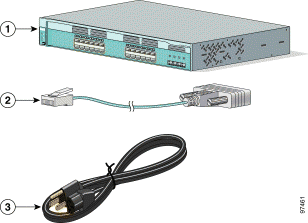
Remove the items shown in Figure D-1 from the shipping container:
|
Note You need to provide the Category 5 straight-through cables to connect the switch ports to other Ethernet devices. |
|
Note On switches running Cisco IOS Release 12.1(14)EA1 or later, you can use the
mdix auto command in the CLI to enable the automatic crossover feature. When
the automatic crossover feature is enabled, the switch detects the required cable
type for copper Ethernet connections and configures the interfaces accordingly.
Therefore, you can use either a crossover or a straight-through cable for
connections to a copper 10/100/1000 port on the switch, regardless the type of
device on the other end of the connection. The automatic crossover feature is disabled by default. For configuration information for this feature, refer to the switch software configuration guide or the switch command reference. |
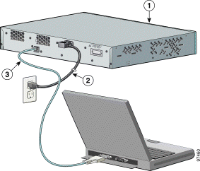
You can use the console port to perform the initial configuration. To connect the switch console port to a PC, use the supplied RJ-45-to-DB-9 adapter cable.
Follow these steps to connect the PC or terminal to the switch:
Step 2 Attach the DB-9 female DTE of the adapter cable to a PC serial port, or attach an appropriate adapter to the terminal.
Before you power on the switch, start the terminal emulation session so that you can see the output display from the power-on self-test (POST).
The terminal-emulation software—frequently a PC application such as Hyperterminal or ProcommPlus—makes communication between the switch and your PC or terminal possible.
Step 2 Start a terminal-emulation session.
Step 3 Configure the baud rate and character format of the PC or terminal to match these console port default characteristics:
Follow these steps to connect to a power source:
Step 2 Connect the other end of the power cable to a grounded AC outlet.
|
Note If you are connecting the switch to a Cisco redundant power system (RPS), refer to the documentation that shipped with your RPS. |
As the switch powers on, it begins POST, a series of tests that run automatically to ensure that the switch functions properly. If POST fails, see "Troubleshooting," to determine a course of action.
If you started the terminal emulation program before you powered on your switch, the PC or terminal displays the bootloader sequence. You need to press Enter to display the setup program prompt.
To set up the switch, you need to complete the setup program, which runs automatically after the switch is powered up. You must assign an IP address and other configuration information necessary for the switch to communicate with the local routers and the Internet. This information is also required if you plan to use the Cluster Management Suite (CMS) to configure and manage the switch.
You will need this information from your network administrator before you complete the setup program:
Follow these steps to complete the setup program and to create an initial configuration for the switch:
Step 2 Enter a host name for the switch, and press Return.
On a command switch, the host name is limited to 28 characters; on a member switch to 31 characters. Do not use -n, where n is a number, as the last character in a host name for any switch.
Step 3 Enter an enable secret password, and press Return.
The password can be from 1 to 25 alphanumeric characters, can start with a number, is case sensitive, allows spaces, but ignores leading spaces. The secret password is encrypted and the enable password is in plain text.
Step 4 Enter an enable password, and press Return.
Step 5 Enter a virtual terminal (Telnet) password, and press Return.
The password can be from 1 to 25 alphanumeric characters, is case sensitive, allows spaces, but ignores leading spaces.
Step 6 (Optional) Configure Simple Network Management Protocol (SNMP) by responding to the prompts. You can also configure SNMP later through the CLI or CMS interface. To configure SNMP later, enter no.
Step 7 Enter the interface name (physical interface or VLAN name) of the interface that connects to the management network, and press Return. For this release, always use vlan1 as that interface.
Step 8 Configure the interface by entering the switch IP address and subnet mask and pressing Return. The IP address and subnet masks shown below are examples.
Step 9 Enter Y to configure the switch as the cluster command switch. Enter N to configure it as a member switch or as a standalone switch.
If you enter N, the switch appears as a candidate switch in the CMS. You can configure the switch as a command switch later through the CLI or CMS interface. To configure it later, enter no.
You have now completed the initial configuration of the switch, and the switch displays its initial configuration. This is an example of output that appears:
Step 10 These choices are displayed:
Make your selection, and press Return.
After you complete the setup program, the switch can run the default configuration that you created. If you want to change this configuration or want to perform other management tasks, use one of these tools:
To use the CLI, enter commands at the Switch> prompt through the console port by using a terminal program or through the network by using telnet. For configuration information, refer to the switch software configuration guide or the switch command reference.
To use the CMS, go to "Managing the Switch by Using the Cluster Management Suite."
![]()
![]()
![]()
![]()
![]()
![]()
![]()
![]()
Posted: Thu Aug 21 11:12:40 PDT 2003
All contents are Copyright © 1992--2003 Cisco Systems, Inc. All rights reserved.
Important Notices and Privacy Statement.