|
|

This chapter describes how to install your switch, interpret the power-on self-test (POST), and connect the switch to other devices. Read these topics and perform the procedures in this order:
This section provides information about these topics:
These warnings are translated into several languages in "Translated Safety Warnings."
 |
Warning This equipment is to be installed and maintained by service personnel only as defined by AS/NZS 3260 Clause 1.2.14.3 Service Personnel. |
 |
Warning Only trained and qualified personnel should be allowed to install or replace this equipment. |
 |
Warning Read the installation instructions before you connect the system to its power source. |
 |
Warning Unplug the power cord before you work on a system that does not have an on/off switch. |
 |
Warning Do not stack the chassis on any other equipment. If the chassis falls, it can cause severe bodily injury and equipment damage. |
 |
Warning The plug-socket combination must be accessible at all times because it serves as the main disconnecting device. |
 |
Warning When installing the unit, always make the ground connection first and disconnect it last. |
 |
Warning This equipment is intended to be grounded. Ensure that the host is connected to earth ground during normal use. |
 |
Warning Do not work on the system or connect or disconnect cables during periods of lightning activity. |
 |
Warning Ultimate disposal of this product should be handled according to all national laws and regulations. |
 |
Warning Attach only the Cisco RPS (model PWR300-AC-RPS-N1) to the RPS receptacle. |
 |
Warning Class 1 laser product |
 |
Warning Avoid exposure to the laser beam. |
This section includes specific regulatory statements about the Catalyst 2950 switches.
U.S. regulatory information for this product is in the front matter of this manual.
This is a Class A Information product. When used in a residential environment, it may cause radio frequency interference. Under such circumstances, the user may be requested to take appropriate countermeasures.

This is a Class A product based on the standard of the Voluntary Control Council for Interference by Information Technology Equipment (VCCI). If this equipment is used in a domestic environment, radio disturbance may arise. When such trouble occurs, the user may be required to take corrective actions.

| |||
|
| ||
This equipment is a Class A product and should be used and installed properly according to the Hungarian EMC Class A requirements (MSZEN55022). Class A equipment is designed for typical commercial establishments for which special conditions of installation and protection distance are used.
Figyelmeztetés a felhasználói kézikönyv számára:
Ez a berendezés "A" osztályú termék, felhasználására és üzembe helyezésére a magyar EMC "A" osztályú követelményeknek (MSZ EN 55022) megfeleloen kerülhet sor, illetve ezen "A" osztályú berendezések csak megfelelo kereskedelmi forrásból származhatnak, amelyek biztosítják a megfelelo speciális üzembe helyezési körülményeket és biztonságos üzemelési távolságok alkalmazását.
When determining where to place the switch, observe these guidelines.
 |
Note If the switch is installed in a closed or multirack assembly, the temperature around it might be greater than normal room temperature. |
 |
Note Carefully remove the contents from the shipping container, and check each item for damage. If any item is missing or damaged, contact your Cisco representative or reseller for support. Return all packing materials to the shipping container and save them. |
The switch is shipped with these items:
 |
Note The DC-switch kit ships only with the Catalyst 2950G-24-EI-DC switch. |
If you want to connect a terminal to the switch console port, you need to provide an RJ-45-to-DB-25 female DTE adapter. You can order a kit (part number ACS-DSBUASYN=) with that adapter from Cisco.
You can connect a 100BASE-FX or 1000BASE-SX port to an SC or ST port on a target device by using one of the MT-RJ fiber-optic patch cables listed in Table 2-1. Use the Cisco part numbers in Table 2-1 to order the patch cables that you need.
| Type | Cisco Part Number |
|---|---|
1-meter, MT-RJ-to-SC multimode cable | CAB-MTRJ-SC-MM-1M |
3-meter, MT-RJ-to-SC multimode cable | CAB-MTRJ-SC-MM-3M |
5-meter, MT-RJ-to-SC multimode cable | CAB-MTRJ-SC-MM-5M |
1-meter, MT-RJ-to-ST multimode cable | CAB-MTRJ-ST-MM-1M |
3-meter, MT-RJ-to-ST multimode cable | CAB-MTRJ-ST-MM-3M |
5-meter, MT-RJ-to-ST multimode cable |
 |
Note Figure 2-1 to Figure 2-17 show the Catalyst 2950-24, 2950G-24-EI-DC, and 2950G-48-EI switches as examples. You can install other Catalyst 2950 switches in a rack as shown in these illustrations. |
To install the switch in a 19-, 23-, or 24-inch rack, follow these steps:
 |
Note Installing the Catalyst 2950G-48-EI switch in a 23-inch or 24-inch rack requires an optional bracket kit not included with the switch. You can order a kit containing the 23-inch or 24-inch rack-mounting brackets and hardware from Cisco (part number RCKMNT-1RU=). |
The bracket orientation and the screws that you use depend on whether you are attaching the brackets to a 19-, 23-, or 24-inch rack. Follow these guidelines:
Figure 2-1 to Figure 2-15 show how to attach a bracket to one side of the switch. Follow the same steps to attach the second bracket to the opposite side of the switch.
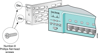
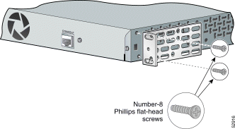

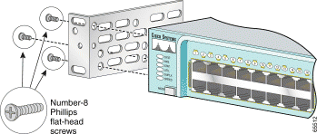

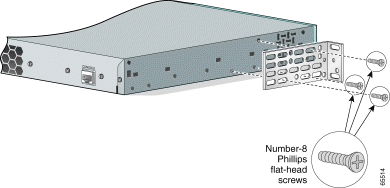

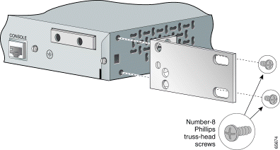
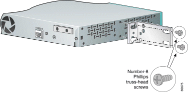
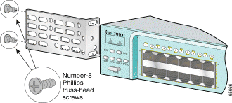
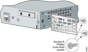
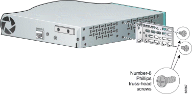
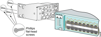
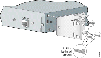

After attaching the brackets, use the four Phillips machine screws to securely attach the brackets to the rack, as shown in Figure 2-16.
To prevent the cables from obscuring the switch and other devices in the rack, you can also attach the cable guide to the rack. See the"Attaching the Optional Cable Guide" section for instructions.

After mounting the switch in the rack, start the terminal-emulation software, and provide power to the switch. See the "Powering On the Switch" section for instructions.
We recommend attaching the cable guide to prevent the cables from obscuring the front panels of the switch and other devices installed in the rack. Use the supplied black Phillips machine screw to attach the cable guide to the left or right bracket, as shown in Figure 2-17.

Before placing the switch on a table, shelf, or desk, locate the adhesive strip with rubber feet in the mounting-kit envelope, and attach four rubber feet to the recessed areas on the switch bottom. Place the switch on a table, shelf, or desk near an AC power source or DC-input power source.
Start the terminal-emulation software and provide power to the switch. See the "Powering On the Switch" section for instructions.
Figure 2-18, Figure 2-19, and Figure 2-20 show how to insert a GBIC module in a GBIC module slot on the switch. For instructions about how to install a CWDM GBIC module in a GBIC module slot, refer to the documentation that came with that GBIC module.
For detailed instructions on installing, removing, and cabling the GBIC module (the 1000BASE-X module, the 1000BASE-T module, the CWDM GBIC module, or the GigaStack module), refer to your GBIC documentation.
 |
Caution To prevent electrostatic-discharge (ESD) damage when installing GBIC modules, follow your normal board and component handling procedures. |


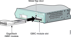
Before connecting the AC power cord, a DC-input power source, or the Redundant Power System (RPS) to the switch, make sure that you have started the terminal-emulation software (such as ProComm, HyperTerminal, tip, or minicom) from your management station.
If you are using the AC power cord, connect the AC power cord to the AC power connector and to an AC power outlet.
If you are using the DC-input power source, see the "Connecting to DC Power" section for installation instructions.
If you are using an RPS, refer to the documentation that came with your RPS for installation instructions.
 |
Warning Attach only the Cisco RPS 300 (model PWR300-AC-RPS-N1) to the RPS receptacle. |
For POST information, see the "Running POST" section.
To connect the Catalyst 2950G-24-EI-DC switch to a DC-input power source, follow these steps:
 |
Warning The equipment is to be installed in a restricted access area. |
 |
Warning Ethernet cables must be shielded when used in a central office environment. |
Locate the DC terminal block plug, the ground lug, and the two number-10-32 screws in the DC-switch kit.
Obtain these necessary tools and equipment:
 |
Warning This equipment is intended to be grounded. Ensure that the host is connected to earth ground during normal use. |
 |
Warning When installing the unit, always make the ground connection first and disconnect it last. |
 |
Caution To make sure that the equipment is reliably connected to earth ground, follow the grounding procedure instructions, and use a UL-listed lug suitable for number-6 AWG wire and two number-10-32 ground-lug screws. |
To ground the switch to earth ground, follow these steps. Make sure to follow any grounding requirements at your site.
Step 1 Locate the ground lug and the two number-10-32 screws from the switch rear panel. Use a standard Phillips screwdriver or a ratcheting torque screwdriver with a Phillips head. Set the screws and the ground lug aside.
Step 2 If your ground wire is insulated, use a wire stripping tool to strip the 6-gauge ground wire to 0.5 inch (12.7 millimeter [mm]) ± 0.02 inch (0.5 mm) as shown in Figure 2-21.

Step 3 Slide the open end of the ground lug over the exposed area of the 6-gauge wire.
Step 4 Using a Panduit crimping tool, crimp the ground lug to the 6-gauge wire.
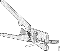
Step 5 Use the two number-10-32 screws to attach the ground lug and wire assembly to the switch rear panel.
Step 6 Using a ratcheting torque screwdriver, torque each ground-lug screw to 15 lbf-in. (240 ounce-force inches [ozf-in.]).

 |
Warning Only trained and qualified personnel should be allowed to install or replace this equipment. |
 |
Caution You must connect the Catalyst 2950G-24-EI-DC switch only to a DC-input power source that has an input supply voltage from -36 to -72 VDC. If the supply voltage is not in this range, the switch might not operate properly or might be damaged. |
 |
Caution The switch must be installed with 5A-branch-circuit protection. |
 |
Note This installation must comply with all applicable codes. |
To wire the switch to a DC-input power source, follow these steps:
Step 1 Locate the terminal block plug (see Figure 2-24).
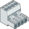
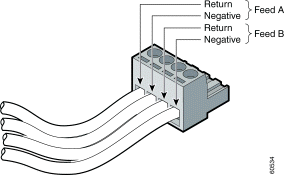
Step 2 Identify the positive and negative feed positions for the terminal block connection. The wiring sequence is positive to positive and negative to negative for both the A and the B feed wires. The switch rear panel identifies the positive and negative positions for both the A and B feed wires.
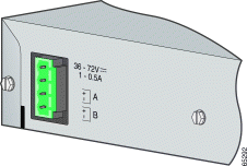
Step 3 Using an 18-gauge wire-stripping tool, strip each of the four wires coming from the DC-input power source to 0.27 inch (6.6 mm) ± 0.02 inch (0.5 mm). Do not strip more than 0.29 inch (7.4 mm) of insulation from the wire. Stripping more than the recommended amount of wire can leave exposed wire from the terminal block plug after installation.

Step 4 Insert the exposed wire of one of the four DC-input power source wires into the terminal block plug, as shown in Figure 2-27. Make sure that you cannot see any wire lead. Only wire with insulation should extend from the terminal block.
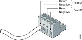
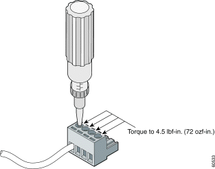
Step 5 Use a ratcheting torque screwdriver to torque the terminal block captive screw (above the installed wire lead) to 4.5 lbf-in. (72 ozf-in.). (See Figure 2-28.)
 |
Caution Do not overtorque the terminal-block captive screws. The recommended maximum torque is 4.5 lbf-in. |
Step 6 Repeat Steps 4 and 5 for the remaining three DC-input power source wires. Figure 2-29 shows the completed wiring of a terminal block plug.
Step 7 Insert the terminal block plug in the terminal block header on the switch rear panel (see Figure 2-30).
 |
Caution Secure the wires coming in from the terminal block so that they cannot be disturbed by casual contact. For example, use tie wraps to secure the wires to the rack. |

Step 8 Remove the tape from the circuit-breaker switch handle, and move the circuit-breaker handle to the on position.
After the power is connected, the switch automatically begins POST, a series of tests that verifies that the switch functions properly. When the switch begins POST, the system LED is off. If POST completes successfully, the LED turns green. If POST fails, the LED turns amber. See "Troubleshooting," to determine a corrective action.
 |
Note POST failures are usually fatal. Call Cisco Systems immediately if your switch does not pass POST. |
Connecting devices that do not autonegotiate or devices with manually set speed and duplex parameters can reduce performance or result in link failures between the devices. To maximize performance, choose one of these methods for configuring the ports:
When connecting the ports on the Catalyst 2950G-24-EI-DC switches to other devices, follow these guidelines:
 |
Caution To comply with the intrabuilding lightning surge requirements, intrabuilding wiring must be shielded, and the shield for the wiring must be grounded at both ends. |
 |
Caution The Catalyst 2950G-24-EI-DC switch is suitable only for intrabuilding or nonexposed wiring connections. |
Follow these steps to connect the switch to 10BASE-T, 100BASE-TX, or 1000BASE-T devices:
 |
Caution To prevent electrostatic-discharge (ESD) damage, follow your normal board and component handling procedures. |
Step 1 When connecting to servers, workstations, and routers, insert a twisted-pair straight-through cable in a front-panel RJ-45 connector, as shown in Figure 2-31, Figure 2-32, and Figure 2-33. When connecting to switches or repeaters, insert a twisted-pair crossover cable. (See the "Cable and Adapter Specifications" section for cable-pinout descriptions.)
 |
Note When connecting to 1000BASE-T devices, be sure to use a four twisted-pair, Category 5 cable. |
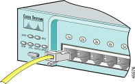

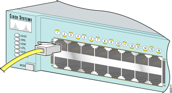
Step 2 Insert the other cable end in an RJ-45 connector on the target device.
Step 3 Observe the port status LED.
The LED turns green when the switch and the target device have an established link.
The LED turns amber while Spanning Tree Protocol (STP) discovers the network topology and searches for loops. This process takes about 30 seconds, and then the LED turns green.
If the LED is off, the target device might not be turned on, there might be a cable problem, or there might be a problem with the adapter installed in the target device. See "Troubleshooting," for solutions to cabling problems.
Step 4 Reconfigure and restart the target device if necessary.
Step 5 Repeat Steps 1 through 4 to connect each port.
The 100BASE-FX and 1000BASE-SX ports operate only in full-duplex mode.
You can connect a 100BASE-FX or 1000BASE-SX port to an SC or ST port on another device by using one of the MT-RJ fiber-optic patch cables listed in Table 2-1. Use the Cisco part numbers in Table 2-1 to order the patch cables that you need.
Follow these steps to connect the switch to a 100BASE-FX or 1000BASE-SX device:
 |
Caution Do not remove the dust plugs from the fiber-optic ports or the rubber caps from the fiber-optic cable until you are ready to connect the cable. The plugs and caps protect the fiber-optic ports and cables from contamination and ambient light. |
Step 1 Remove the dust plugs from the 100BASE-FX or 1000BASE-SX port and the rubber caps from the MT-RJ patch cable. Store them for future use.
Step 2 Insert the cable in a 100BASE-FX or 1000BASE-SX port. (See Figure 2-34.)

Step 3 Insert the other cable end in an SC or ST port on the target device.
Step 4 Observe the port status LED.
The LED turns green when the switch and the target device have an established link.
The LED turns amber while STP discovers the network topology and searches for loops. This process takes about 30 seconds, and then the port LED turns green.
If the LED is off, the target device might not be turned on, there might be a cable problem, or there might be a problem with the adapter installed in the target device. See "Troubleshooting," for solutions to cabling problems.
Step 5 Reconfigure and restart the target device if necessary.
Step 6 Repeat Steps 1 through 5 to connect each port.
These sections describe how to connect to a GBIC module port.
For instructions about how to connect to the CWDM GBIC module ports, refer to the documentation that came with that GBIC module.
When connecting the ports on the Catalyst 2950G-24-EI-DC switches to other devices, follow these guidelines:
 |
Caution To comply with the intrabuilding lightning surge requirements, intrabuilding wiring must be shielded, and the shield for the wiring must be grounded at both ends. |
 |
Caution The Catalyst 2950G-24-EI-DC switch is suitable only for intrabuilding or nonexposed wiring connections. |
 |
Caution Do not remove the rubber plugs from the GBIC module port or the rubber caps from the fiber-optic cable until you are ready to connect the cable. The plugs and caps protect the GBIC module ports and cables from contamination and ambient light. |
After installing the 1000BASE-X GBIC in the GBIC module slot, follow these steps:
Step 1 Remove the rubber plugs from the GBIC module port, and store them for future use.
Step 2 Insert the SC connector in the fiber-optic receptacle (see Figure 2-35).
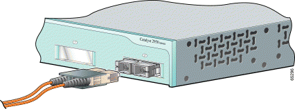
Step 3 Insert the other cable end in a fiber-optic receptacle on a target device.
Step 4 Observe the port status LED.
The LED turns green when the switch and the target device have an established link.
The LED turns amber while STP discovers the network topology and searches for loops. This process takes about 30 seconds, and then the port LED turns green.
If the LED is off, the target device might not be turned on, there might be a cable problem, or there might be problem with the adapter installed in the target device. See Chapter 3, "Troubleshooting," for solutions to cabling problems.
Step 5 Reconfigure and restart the switch or target device if necessary.
After installing the 1000BASE-T GBIC in the GBIC module slot, follow these steps:
 |
Caution To prevent ESD damage, follow your normal board and component handling procedures. |
Step 1 When connecting to servers, workstations, and routers, insert a four twisted-pair, straight-through cable in the RJ-45 connector. When connecting to switches or repeaters, insert a four twisted-pair, crossover cable (see Figure 2-36).
 |
Note When connecting to a 1000BASE-T device, be sure to use a four twisted-pair, Category 5 cable. |
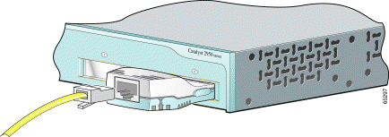
Step 2 Insert the other cable end in an RJ-45 connector on a target device.
Step 3 Observe the port status LED.
The LED turns green when the switch and the target device have an established link.
The LED turns amber while STP discovers the network topology and searches for loops. This process takes about 30 seconds, and then the LED turns green.
If the LED is off, the target device might not be turned on, there might be a cable problem, or there might be a problem with the adapter installed in the target device. See Chapter 3, "Troubleshooting," for solutions to cabling problems.
Step 4 Reconfigure and restart the switch or target device, if necessary.
After installing the GigaStack GBIC in the GBIC module slot, follow these steps:
Step 1 Insert the GigaStack cable connector in the GBIC (see Figure 2-37).

Step 2 Insert the other cable end in a port on a target device.
Step 3 Observe the port status LED.
The LED turns green when the switch and the target device have an established link.
The LED turns amber while STP discovers the network topology and searches for loops. This process takes about 30 seconds, and then the port LED turns green.
If the LED is off, the target device might not be turned on, there might be a cable problem, or there might be a problem with the adapter installed in the target device. See "Troubleshooting," for solutions to cabling problems.
Step 4 Reconfigure and restart the switch or target device, if necessary.
If you want to connect a PC to the console port, use the supplied RJ-45-to-DB-9 adapter cable. If you want to connect a terminal to the console port, you need to provide an RJ-45-to-DB-25 female DTE adapter. You can order a kit (part number ACS-DSBUASYN=) with that adapter from Cisco. For console-port and adapter-pinout information, see the"Cable and Adapter Specifications" section.
The PC or terminal must support VT100 terminal emulation. The terminal-emulation software—frequently a PC application such as HyperTerminal or Procomm Plus—makes communication between the switch and your PC or terminal possible during the setup program.
Follow these steps to connect your PC or terminal to the console port:
Step 1 Make sure that your terminal-emulation software is configured to communicate with the switch through hardware flow control.
Step 2 Configure the baud rate and character format of the PC or terminal to match these console-port default characteristics:
After gaining access to the switch, you can change the port baud rate. Refer to the switch software configuration guide for instructions.
Step 3 Insert the adapter cable in the console port, as shown in Figure 2-38, Figure 2-39, and Figure 2-40. (See the "Cable and Adapter Pinouts" section for pinout descriptions.)
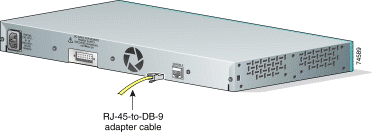
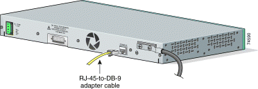
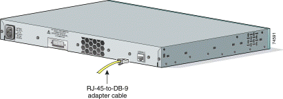
Step 4 Attach the appropriate adapter to the terminal, if needed.
Step 5 Insert the other adapter cable end in the PC or terminal adapter.
Step 6 Start the terminal-emulation software.
For information about starting up the switch, refer to the Release Notes for the Catalyst 2950 Switch.
For information about configuring the switch, refer to the switch software configuration guide.
![]()
![]()
![]()
![]()
![]()
![]()
![]()
![]()
Posted: Tue Sep 10 22:24:12 PDT 2002
All contents are Copyright © 1992--2002 Cisco Systems, Inc. All rights reserved.
Important Notices and Privacy Statement.