cc/td/doc/product/lan/cat2948
hometocprevnextglossaryfeedbacksearchhelp
PDF

Table Of Contents

Configuring the Gigabit Ethernet Ports

Installing, Removing, and Maintaining GBICs

GBIC Features

Port Cabling Specifications

GBIC Optical Power Characteristics

GBIC Cabling Restrictions

Installing GBICs

Removing GBICs

GBIC Maintenance Guidelines

Patch Cord

Connecting To an SFP Module


Configuring the Gigabit Ethernet Ports


Warning Before you install, operate, or service the system, read the Site Preparation and Safety Guide. This guide contains important safety information you should know before working with the system. Statement 200


Warning Only trained and qualified personnel should be allowed to install, replace, or service this equipment. Statement 1030


This chapter describes how to configure the Gigabit Ethernet ports on the Catalyst 2948G and 2980G switches and how to configure the small form-factor-pluggable (SFP) module slot on the Catalyst 2948G-GE-TX switches. The chapter contains these sections:

Installing, Removing, and Maintaining GBICs

Connecting To an SFP Module

The Gigabit Ethernet ports can be configured with any combination of GBICs. The Gigabit Ethernet ports on these modules are used primarily for backbone interconnection of other high-performance switches and routers.

Installing, Removing, and Maintaining GBICs

The following sections describe Gigabit Interface Converters (GBICs) and how to install, remove, and maintain them:

GBIC Features

Port Cabling Specifications

GBIC Optical Power Characteristics

GBIC Cabling Restrictions

Installing GBICs

Removing GBICs

GBIC Maintenance Guidelines

Patch Cord

GBIC Features


Warning Because invisible laser radiation may be emitted from the aperture of the port when no cable is connected, avoid exposure to laser radiation and do not stare into open apertures. Statement 70


GBICs (see Figure 4-1) are hot-swappable input/output devices that plug into a Gigabit Ethernet switching module, linking the module with a fiber-optic network. The GBICs use SC-type connectors and plug into connectors on the module. You can install any combination of GBICs in the Gigabit Ethernet switching module.

Figure 4-1 GBIC Module

Table 4-1 lists the GBIC modules that are supported by the Catalyst 2948G and 2980G switches.

Table 4-1 Supported GBIC modules

GBIC Type
Model Number

Fiber-optic 1000BASE-SX

WS-G5484=

Fiber-optic 1000BASE-LX/LH

WS-G5486=

Fiber-optic 1000BASE-ZX

WS-G5487=

Copper 1000BASE-TX GBIC

WS-G5483=

Coarse Wave Division Multiplexing (CWDM) fiber-optic 1000BASE-X GBIC

CWDM-GBIC-1470= CWDM-GBIC-1490= CWDM-GBIC-1510= CWDM-GBIC-1530= CWDM-GBIC-1550= CWDM-GBIC-1570= CWDM-GBIC-1590= CWDM-GBIC-1610=


Note Cisco 1000BASE-LX/LH interfaces fully comply with the IEEE 802.3z 1000BASE-LX standard. However, their higher optical quality allows them to reach 10 kilometers over single-mode fiber (SMF) versus the 5 kilometers specified in the standard.


Other GBIC media types may be supported as additional technology becomes available.


Note Because of interoperability issues, Cisco does not support GBICs purchased from third-party vendors.


Port Cabling Specifications

Table 4-2 provides cabling specifications for the GBICs. The minimum cable distance for all GBICs listed (MMF [multimode fiber] and SMF) is 6.5 feet (2 meters).


Note For information about the Coarse Wave Division Multiplexing (CWDM), refer to the Cisco CWDM GBIC and CWDM SFP Installation Note.


Table 4-2 GBIC Port Cabling Specifications 

GBIC
Wavelength1 (nm)
Fiber Type
Core Size (microns)
Modal Bandwidth
(MHz/km)
Maximum Cable Distance

SX2

850

MMF

62.5

160

722 ft (220 m)


62.5

200

902 ft (275 m)


50.0

400

1640 ft (500 m)


50.0

500

1804 ft (550 m)

LX/LH

1300

MMF3

62.5

500

1804 ft (550 m)


50.0

400

1804 ft (550 m)


50.0

500

1804 ft (550 m)


SMF

9/10

-

6.2 mi (10 km)

ZX

1550

SMF

9/10

-

43.5 mi (70 km)


SMF4

-

-

62.1 mi (100 km)

1 Nominal fiber specification wavelength.

2 MMF only.

3 Patch cord required (refer to the "Patch Cord" section for details).

4 Dispersion-shifted single-mode fiber-optic.


GBIC Optical Power Characteristics

Table 4-3 provides the GBIC optical power characteristics.


Note For information about the Coarse Wave Division Multiplexing (CWDM), refer to the Cisco CWDM GBIC and CWDM SFP Installation Note.


Table 4-3 GBIC Optical Power Characteristics 

Parameter
1000BASE-SX
(WS-G5484)
1000BASE-LX/LH
(WS-G5486)
1000BASE-ZX
(WS-G5487)

Transmitter output power (min/max)

0/-9.5 dBm

-3/-9.5 dBm

0/4.77 dBm

Receiver maximum input power

0 dBm

-3 dBm

-3 dBm

Receiver sensitivity

-17 dBm

-19 dBm

-23 dBm

Channel insertion loss


50/125 micron1 MMF

3.4 dBm

4.4 dBm

-

62.5/125 micron MMF

3.2 dBm

6 dBm

-

9/10 micron SMF

-

6.5 dBm

21.5 dBm

1 1 micron (m) equals 1 micrometer or 10-6 meters


GBIC Cabling Restrictions

You must observe the following fiber-optic cabling restrictions when using GBICs:

The minimum cabling distance for 1000BASE-SX and 1000BASE-LX/LH GBICs is 6.5 feet (2 meters).

The maximum cabling distance for each GBIC type is listed in Table 4-2.

When using the 1000BASE-LX/LH GBIC with 62.5-micron diameter MMF, you must install a mode-conditioning patch cord between the MMF fiber-optic network and the GBIC. The mode-conditioning patch cord (CAB-GELX-625 or equivalent) is required to comply with IEEE standards. See the "Patch Cord" section for more information.

You must insert a 10-dB inline optical attenuator between the single-mode fiber-optic network and the receiving port on the 1000BASE-ZX GBIC at each end of the link if the link length is less than 15.5 miles (25 km).

You must insert a 5-dB inline optical attenuator between the single-mode fiber-optic network and the receiving port on the 1000BASE-ZX GBIC at each end of the link if the link is greater than 15.5 miles (25 km), but less than 31 miles (50 km).

Installing GBICs

This section describes how to install GBICs.


Caution Unnecessary removal and insertion of a GBIC could lead to premature failure of the GBIC. A GBIC has a lifetime of 100 to 500 removals and insertions.

A switch can be shipped with or without GBICs installed.


Caution When removing or inserting a GBIC, always wear an ESD wrist strap connected to the ESD wrist strap connector. For more information about ESD, refer to the Site Preparation and Safety Guide.


Note GBICs are online swappable.


To install a GBIC, perform these steps:


Step 1 Remove the GBIC from its protective packaging.

Step 2 Verify that the GBIC is the correct type for your network by checking the part number.

The part number indicates whether it is 1000BASE-SX, 1000BASE-LX/LH, or 1000BASE-ZX.

Step 3 Grip the sides of the GBIC with your thumb and forefinger; insert the GBIC into the slot on the front of the module.

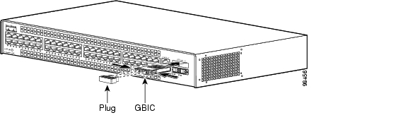
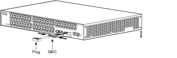
See Figure 4-2 for GBIC installation on a Catalyst 2948G switch. See Figure 4-3 for GBIC installation on a Catalyst 2980G switch.


Note GBICs are keyed to prevent incorrect slot insertion. See Figure 4-4.


Figure 4-2 Installing a GBIC on a Catalyst 2948G Switch

Figure 4-3 Installing a GBIC on a Catalyst 2980G Switch

Step 4 Slide the GBIC into the slot until you hear a click. The click indicates that the GBIC is locked into the slot.

Step 5 When you are ready to attach the fiber-optic cable, remove the plug from the GBIC and save it for future use.


Caution Do not remove the plug from the GBIC optical bores or the fiber-optic cable until you are ready to connect the cable. The plug protects the GBIC optical bores and cable from contamination.

Step 6 Remove the protective plug from the SC-type connector on the fiber-optic cable if necessary. Insert the connector into the GBIC.

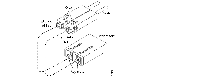
When you plug the SC-type connector into the GBIC, make sure that both the Tx and Rx fiber-optic cables are already fully inserted into the SC-type connector.

Figure 4-4 Connecting the SC-Type Connector


Note If you are using the LX/LH GBIC with MMF, you need to install a patch cord between the GBIC and the MMF cable. See the "Patch Cord" section for details.


Removing GBICs


Note If you are removing the GBIC from an online switch, enter the show port command to verify the type of GBIC that is installed.


To remove a GBIC, perform these steps:


Step 1 Disconnect the fiber-optic cable from the GBIC SC-type connector.

Step 2 Release the GBIC from the slot by simultaneously squeezing the plastic tabs (one on each side of the GBIC).

Step 3 Slide the GBIC out of the slot.

Step 4 Install the plug into the GBIC optical bores and place the GBIC in its protective packaging.


GBIC Maintenance Guidelines

Follow these GBIC maintenance guidelines:

GBICs are static sensitive. To prevent ESD damage, follow your normal board and component handling procedures.

GBICs are dust sensitive. When the GBIC is stored or when a fiber-optic cable is not plugged in, always keep plugs in the GBIC optical bores.

The most common source of contaminants in the optical bores is debris picked up on the ferrules of the optical connectors. Use an alcohol swab or Kim-Wipe to clean the ferrules of the optical connector.

Patch Cord

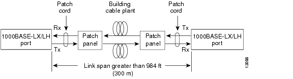
When using the LX/LH GBIC with a 62.5-micron diameter core size MMF, you must install a mode-conditioning patch cord (Cisco product number CAB-GELX-625 or equivalent) between the GBIC and the MMF cable on both the transmit and receive ends of the link. The patch cord is required for link distances greater than 984 feet (300 meters).


Note We do not recommend using the LX/LH GBIC with MMF without a patch cord for very short link distances (tens of meters). The result could be an elevated bit error rate (BER).


Note The patch cord is required to comply with IEEE standards. The IEEE found that link distances could not be achieved with certain types of fiber-optic cable due to a problem in the center of some fiber-optic cable cores. The solution is to launch light from the laser at a precise offset from the center by using the patch cord. At the output of the patch cord, the LX/LH GBIC is compliant with the IEEE 802.3z standard for 1000BASE-LX. For a detailed description of this problem, refer to Appendix C, "Differential Mode Delay."


Note Cisco Gigabit Ethernet products have been tested and evaluated to comply with the standards listed in Appendix A, "Specifications." Equivalent cables should also meet these standards.


Patch Cord Configuration Example

Figure 4-5 shows a typical configuration using patch cords.

Figure 4-5 Patch Cord Configuration

Patch Cord Installation

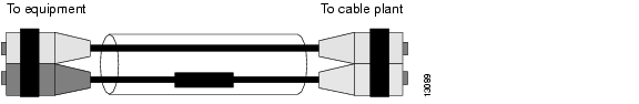
Plug the end of the patch cord labeled "To equipment" into the GBIC (see Figure 4-6). Plug the end labeled "To cable plant" into the patch panel. The patch cord is 9.84 feet (3 meters) long and has duplex SC-type male connectors at each end.

Figure 4-6 Patch Cord Installation

Connecting To an SFP Module

This section describes how to connect to an SFP module. For instructions about how to install or remove an SFP module, refer to the Cisco Small Form-Factor Pluggable Modules Installation Notes (not orderable but is available on Cisco.com) and to the documentation that came with your SFP module.

Table 4-4 lists the SFP modules supported by the Catalyst 2948G-GE-TX switch.

Table 4-4 Supported SFP Modules 

SFP Type
Model Number

Fiber-optic 1000BASE-LX

GLC-LS-SM=

Fiber-optic 1000BASE-SX

GLC-SX-MM=

Fiber-optic 1000BASE-ZX

GLC-ZX-SM=

Copper 1000BASE-T

GLC-T=

Coarse Wave Division Multiplexing (CWDM) fiber-optic SFP modules

CWDM-SFP-1470= CWDM-SFP-1490= CWDM-SFP-1510= CWDM-SFP-1530= CWDM-SFP-1550= CWDM-SFP-1570= CWDM-SFP-1590= CWDM-SFP-1610=


The restrictions are that each port must match the wave-length specifications on the other end of the cable, and the cable must not exceed the recommended cable length for reliable communications. Table 4-5 lists these recommendations.

Table 4-5 Fiber-Optic SFP Module Port Cabling Specifications

SFP Module
Wavelength (nanometers)
Fiber Type
Core Size (micron)
Modal Bandwidth (MHz/km)
Cable Distance

1000BASE-SX

850

MMF

62.5
62.5
50.0
50.0

160
200
400
500

722 ft (220 m)
902 ft (275 m)
1640 ft (500 m)
1804 ft (550 m)

1000BASE-LX/LH

1300

MMF1

SMF

62.5
50.0
50.0
9/10

500
400
500

1804 ft (550 m)
1804 ft (550 m)
1804 ft (550 m)
6.2 mi (10 km)

1000BASE-ZX

1550

SMF

9/10

43.4 to 62 mi (70 to 100 km)2

1 A mode-conditioning patch cord is required. Using an ordinary patch cord with MMF, 1000BASE-LX/LH SFP modules, and a short link distance can cause transceiver saturation, resulting in an elevated bit error rate (BER). When using the LX/LH SFP module with 62.5-micron diameter MMF, you must also install a mode-conditioning patch cord between the SFP module and the MMF cable on both the sending and receiving ends of the link. The mode-conditioning patch cord is required for link distances greater than 984 feet (300 m).

2 1000BASE-ZX SFP modules can reach up to 100 km by using dispersion-shifted SMF or low-attenuation SMF; the distance depends on the fiber quality, the number of splices, and the connectors.


Note For information about the Coarse Wave Division Multiplexing (CWDM), refer to the Cisco CWDM GBIC and CWDM SFP Installation Note.


The 1000BASE-T (copper) SFP module is used to establish a Gigabit Ethernet connection through a Category 5 Category 5 cable.

Use only Cisco SFP modules on the Catalyst 2948G-GE-TX switch. Each SFP module has an internal serial EEPROM that is encoded with security information. This encoding provides a way for Cisco to identify and validate that the SFP module meets the requirements for the switch.

For more information about these SFP modules, refer to your SFP module documentation and to the Cisco Small Form-Factor Pluggable Modules Installation Notes (not orderable but is available on Cisco.com.)

For the latest information about SFP modules supported by the switch, refer to the release notes.


Caution Do not remove the rubber plugs from the ports on fiber-optic SFP modules or the rubber caps from the the fiber-optic cable until you are ready to connect the cable. The plugs and caps protect the SFP module ports and cables from contamination and ambient light.

Before connecting to an SFP module, be sure that you understand the port and cabling stipulations in
Table 4-5. See Appendix A, "Specifications," for information about the LC on the SFP modules for fiber-optic connections.

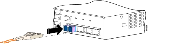
Follow these steps to connect a fiber-optic cable to an SFP module:


Warning Invisible laser radiation may be emitted from disconnected fibers or connectors. Do not stare into beams or view directly with optical instruments. Statement 272


Step 1 Remove the rubber plugs from the module port and fiber-optic cable, and store them for future use.

Step 2 Insert one end of the fiber-optic cable into the SFP module port, as shown in Figure 4-7.

Figure 4-7 Connecting to an SFP Module Port

Step 3 Insert the other cable end in a fiber-optic receptacle on a target device.

Step 4 Observe the port LED.

The LED turns green when the switch and the target device have an established link.

The LED turns amber while the STP discovers the network topology and searches for loops. This process takes about 30 seconds, and then the port LED turns green.

If the LED is off, the target device might not be turned on, there might be a cable problem, or there might be problem with the adapter installed in the target device. See Chapter 5, "Troubleshooting the Installation," for solutions to cabling problems.

Step 5 If necessary, reconfigure and restart the switch or target device.

The Gigabit Ethernet ports on these modules are used primarily for backbone interconnection of other high-performance switches and routers.


After you have connected all the interfaces, check all connections, and then perform the steps described in the "Verifying Switch Operation" section on page 3-20 to verify that the switch is operational.


hometocprevnextglossaryfeedbacksearchhelp

Posted: Thu Jan 27 15:38:23 PST 2005
All contents are Copyright © 1992--2005 Cisco Systems, Inc. All rights reserved.
Important Notices and Privacy Statement.