|
|

This chapter describes the equipment and site requirements for installing the Catalyst 2900. It includes the power and cabling requirements that must be in place at the installation site and describes additional equipment you will need to complete the installation and the environmental conditions your site must meet to maintain normal operation. Instructions for unpacking the system and additional equipment are provided in the document Unpacking Instructions, which is attached to the outside of the shipping container.
This chapter includes information about the following preinstallation requirements:
 | Warning Only trained and qualified personnel should be allowed to install or replace the Catalyst 2900. To see translated versions of this warning, refer to the appendix "Translated Safety Warnings." |
 | Warning Read the installation instructions before you connect the system to its power source. To see translated versions of this warning, refer to the appendix "Translated Safety Warnings." |
The following guidelines will help to ensure your safety and protect the equipment. This list is not inclusive of all potentially hazardous situations that you may be exposed to as you install the switch, so be alert.
 | Warning Metal objects heat up when connected to power and ground, and can cause serious burns. To see translated versions of this warning, refer to the appendix "Translated Safety Warnings." |
The switch chassis weighs 41pounds. The chassis is not intended to be moved frequently. Before you install the switch, ensure that your site is properly prepared so you can avoid having to move the chassis later to accommodate power sources and network connections.
Two people are required to lift the chassis. Whenever you lift the chassis or any heavy object, follow these guidelines:
 | Warning Two people are required to lift the chassis. Grasp the chassis underneath the lower edge and lift with both hands. To prevent injury, keep your back straight and lift with your legs, not your back. To prevent damage to the chassis and components, never attempt to lift the chassis with the handles on the power supplies or on the interface processors, or by the plastic panels on the front of the chassis. These handles were not designed to support the weight of the chassis. To see translated versions of this warning, refer to the appendix "Translated Safety Warnings." |

Follow these basic guidelines when working with any electrical equipment:
In addition, use the guidelines that follow when working with any equipment that is disconnected from a power source but still connected to telephone wiring or other network cabling.
 | Warning Do not work on the system or connect or disconnect cables during periods of lightning activity. To see translated versions of this warning, refer to the appendix "Translated Safety Warnings." |
This section discusses the site environment requirements for the switch chassis.
The environmental monitor in the switch protects the system and components from potential damage from overvoltage and overtemperature conditions. To assure normal operation and avoid unnecessary maintenance, plan your site configuration and prepare your site before installation. After installation, make sure the site maintains an ambient temperature of 32 to 104°F (0 to 40°C), and keep the area around the chassis as free from dust as is practical.
The Catalyst 2900 should be installed in an enclosed, secure area such as a wiring closet. The wiring closet provides security, ensuring that only qualified personnel have access to the switch and control of the environment.
 | Warning To prevent the switch from overheating, do not operate it in an area that exceeds the maximum recommended ambient temperature of 104°F (40°C). To prevent airflow restriction, allow at least 3 inches (7.6 cm) of clearance around the ventilation openings. To see translated versions of this warning, refer to the appendix "Translated Safety Warnings." |
The 175W, AC-input power supply uses a power factor corrector (PFC) that allows it to operate on input voltage and current within the ranges of 100 to 240 VAC and 47 to 63 Hz.
 | Warning Do not touch the power supply when the power cord is connected. For systems with a power switch, line voltages are present within the power supply even when the power switch is off and the power cord is connected. For systems without a power switch, line voltages are present within the power supply when the power cord is connected. To see translated versions of this warning, refer to the appendix "Translated Safety Warnings." |
 | Warning Unplug the power cord before you work on a system that does not have an on/off switch. To see translated versions of this warning, refer to the appendix "Translated Safety Warnings." |
 | Warning This product relies on the building's installation for short-circuit (overcurrent) protection. Ensure that a fuse or circuit breaker no larger than 120 VAC, 15A U.S. (240 VAC, 10A international) is used on the phase conductors (all current-carrying conductors). Special note for Germany only: The electrical rating for the main circuit breaker or fuse should be 240 VAC, 16A. To see translated versions of this warning, refer to the appendix "Translated Safety Warnings." |
 | Warning A voltage mismatch can cause equipment damage and may pose a fire hazard. If the voltage indicated on the label is different from the power outlet voltage, do not connect the chassis to that receptacle. To see translated versions of this warning, refer to the appendix "Translated Safety Warnings." |
 | Warning Care must be given to connecting units to the supply circuit so that wiring is not overloaded. To see translated versions of this warning, refer to the appendix "Translated Safety Warnings." |
Note the power consumption rating in Table A-1 in the appendix "System Specifications" for each unit before it is connected.
 | Caution The power outlet must be installed near the equipment and must be easily accessible. |
 | Warning This equipment is intended to be grounded. Ensure that the host is connected to earth ground during normal use.To see translated versions of this warning, refer to the appendix "Translated Safety Warnings." |
The following are guidelines for setting up the plant wiring and cabling at your site. When planning the location of the new system, consider the distance limitations for signaling, electromagnetic interference (EMI), and connector compatibility.
When wires are run for any significant distance in an electromagnetic field, interference can occur between the field and the signals on the wires. This fact has two implications for the construction of plant wiring:
If wires exceed recommended distances, or if wires pass between buildings, give special consideration to the effect of a lightning strike in your vicinity. The electromagnetic pulse (EMP) caused by lightning or other high-energy phenomena can easily couple enough energy into unshielded conductors to destroy electronic devices. If you have had problems of this type in the past, you may want to consult experts in electrical surge suppression and shielding.
Most data centers cannot resolve the infrequent but potentially catastrophic problems just described without pulse meters and other special equipment. These problems can take a great deal of time to identify and resolve, so take precautions by providing a properly grounded and shielded environment, and pay special attention to issues of electrical surge suppression.
The length of your networks and the distances between connections depend on the type of signal, the signal speed, and the transmission media (the type of cabling used to transmit the signals). For example, fiber-optic cable has a greater channel capacity than twisted-pair cabling. The distance and rate limits in this chapter are the IEEE recommended maximum speeds and distances for signaling. If you understand the electrical problems that may arise and can compensate for them, you should get good results with rates and distances greater than those described here; however, do so at your own risk. The following distance limits are provided as guidelines for planning your network connections before installation.
The maximum distances for Ethernet network segments and connections depend on the type of transmission cable used; for example, unshielded twisted-pair (10BaseT). The IEEE recommends a maximum distance of 328 feet (100 meters) between station (connection) and switch for 10BaseT connections using category 5 UTP. See Table 2-1 for maximum cable distances.
| Transceiver Speed | Cable Type | Duplex Mode | Maximum Distance Between Stations |
|---|---|---|---|
| 100 Mbps | Category 5 UTP | Full and half | 328 feet (100 meters) |
| 100 Mbps | Multimode fiber | Full | 1.2 miles (2 km) |
| 100 Mbps | Multimode fiber | Half | 1,312 feet (400 meters) |
The following is an example of multimode power budget calculations based on the following variables:
Estimate the power budget as follows:
The value of 2.5 dB indicates that this link would have sufficient power for transmission.
Statistical models more accurately determine the power budget than the worst-case method. Determining the link loss with statistical methods requires accurate knowledge of variations in the data link components. Statistical power budget analysis is beyond the scope of this document. For further information, refer to User-Network Interface (UNI) Forum specifications, International Telecommunications Union Telecommunications Standardization Sector (ITU-T) standards, and your equipment specifications.
The following publications contain information on determining attenuation and power budget:
As with all signaling systems, serial signals can travel a limited distance at any given bit rate; generally, the slower the baud rate, the greater the distance. Table 2-2 shows the standard relationship between baud rate and distance for EIA/TIA-232 signals.
| Rate (bps) | Distance (Feet) | Distance (Meters) |
|---|---|---|
| 2400 | 200 | 60 |
| 4800 | 100 | 30 |
| 9600 | 50 | 15 |
| 19200 | 25 | 7.6 |
| 38400 | 12 | 3.7 |
| 56000 | 8.6 | 2.6 |
A standard rack-mount kit is provided for mounting the switch in a standard 19-inch equipment rack. The rack-mount kit is not suitable for use with telco-type equipment racks or those with obstructions (such as a power strip) that could impair access to the switching modules and power supplies. Figure 2-2 show the chassis footprint and outer dimensions.
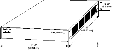
To use the standard rack-mount kit, your equipment rack must meet the following requirements:
When planning your rack installation, consider the following guidelines:
 | Warning To prevent overheating the switch, do not operate it in an area that exceeds the maximum recommended ambient temperature of 104°F (40°C). To prevent airflow restriction, allow at least 3 inches (7.6 cm) of clearance around the ventilation openings. To see translated versions of this warning, refer to the appendix "Translated Safety Warnings." |
 | Caution Never install the switch in an enclosed rack that is not properly ventilated or air-conditioned. |
 | Warning To prevent bodily injury when mounting or servicing the unit in a rack, you must take special precautions to ensure that the system remains stable. The following guidelines are provided to ensure your safety. To see translated versions of this warning, refer to the appendix "Translated Safety Warnings." |
In addition to the preceding guidelines, review the precautions for avoiding overtemperature conditions in the section "Equipment-Rack Ventilation" later in this chapter.
The switch operates as a standalone system mounted in a rack in a secure wiring closet. It requires a dry, clean, well-ventilated, and air-conditioned environment. An internal fan assembly pulls cooling air through the chassis from the right side (intake) to the left side (exhaust) when facing the front of the system. The flow of ambient air must be maintained to ensure normal operation. If the airflow is blocked or restricted, or if the intake air is too warm, an overtemperature condition can occur. Under extreme conditions, the environmental monitor will shut down the system to protect the system components.
To ensure normal operation and avoid unnecessary maintenance, plan your site configuration and prepare your site before installation. After installation, make sure the site maintains an ambient temperature of 0 to 40°C (32 to 104°F), and keep the area around the chassis as free from dust as is practical. For a description of the environmental monitor and status levels, refer to the section "Environmental Monitoring and Reporting Functions" in the chapter ""
If the temperature of the room air drawn into the chassis is higher than desirable, the air temperature inside the chassis may also be too high. This condition can occur when the wiring closet or rack in which the chassis is mounted is not ventilated properly, when the exhaust of one device is placed so it enters the air intake vent of the chassis, or when the chassis is the top unit in an unventilated rack. Any of these conditions can inhibit airflow and create an overtemperature condition.
Multiple switches can be rack-mounted with little or no clearance above and below the chassis. However, when mounting a switch in a rack with other equipment or when placing it on the floor with other equipment located close by, ensure that the exhaust from other equipment does not blow into the intake vent of the chassis.
Table 2-3 lists the operating and nonoperating environmental site requirements. To maintain normal operation and ensure high system availability, maintain an ambient temperature and clean power at your site. The following ranges are those within which the switch will continue to operate; however, a measurement that is approaching the minimum or maximum of a range indicates a potential problem. You can maintain normal operation by anticipating and correcting environmental anomalies before they exceed the maximum operating range.
| Minimum | Maximum | |
|---|---|---|
| Temperature, ambient operating | 32°F (0°C) | 104°F (40°C) |
| Temperature, ambient nonoperating and storage | -4°F (-20°C) | 149°F (65°C) |
| Humidity (RH), ambient (noncondensing) operating | 10% | 90% |
| Humidity (RH), ambient (noncondensing) nonoperating and storage | 5% | 95% |
| Altitude, operating and nonoperating | Sea level | 10,000' (3050 m) |
| Vibration, operating | 5-200 Hz, 0.5 g (1 octave/min.) | |
| Vibration, nonoperating | 5-200 Hz, 1 g (1 octave./min.) 200-500 Hz, 2 g (1 octave/min.) |
Planning a proper location for the switch and the layout of your equipment rack or wiring closet is essential for successful system operation. Equipment placed too close together or inadequately ventilated can cause system overtemperature conditions. In addition, chassis panels made inaccessible by poor equipment placement can make system maintenance difficult. Following are precautions that can help avoid problems during installation and ongoing operation.
Follow these general precautions when planning your equipment locations and connections:
If you plan to install the switch in an equipment rack, follow these precautions to avoid overtemperature conditions. See also the guidelines that are provided in the section "Equipment Racks" earlier in this chapter:
For a functional description of the environmental monitor and the status levels, refer to the section "Environmental Monitoring and Reporting Functions," in the chapter "What Is the Catalyst 2900?"
Take the following precautions when planning power connections to the switch:
 | Warning The device is designed to work with TN power systems. To see translated versions of this warning, refer to the appendix "Translated Safety Warnings." |
When preparing your site for network connections to the switch, you must consider numerous factors related to each type of interface:
The network cabling components shown in Figure 2-3 consist of the following:
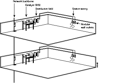
You may need some of the following data communications equipment to complete your installation:
You will need an Ethernet transceiver and transceiver cable between each Ethernet port and the Ethernet network. You can use three different Ethernet connectors:


For multimode fiber-optic cabling (100BaseFX at 100 Mbps), Fast Ethernet transceivers are available from a variety of sources. Figure 2-6 shows examples of transceivers and connection equipment. You can connect either Ethernet Version 1 or Version 2/IEEE 802.3 interfaces; the switch automatically supports both types.
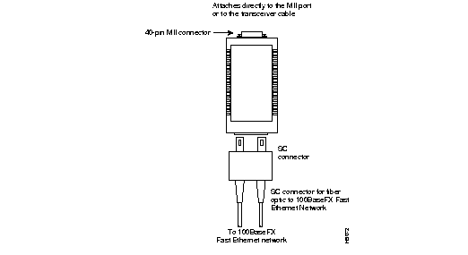
When planning your connections, consider the types and locations of connectors on adjacent switching modules to avoid having the transceiver overlap and impair access to other connections.
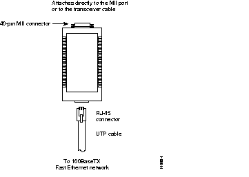
For UTP and fiber optic cabling, Fast Ethernet transceivers are available from a variety of sources. Figure 2-7 shows examples of transceivers and connection equipment. You can connect either Ethernet Version 1 or Version 2/IEEE 802.3 interfaces; the switch automatically supports both types.
The supervisor engine module contains an EIA/TIA-232 asynchronous console port (DB-25 receptacle). Synchronous transmission uses precise timing to synchronize transmissions between the transmitter and receiver, and maintains separate clock and data signals. Asynchronous transmission uses control bits instead of a precise clock signal to indicate the beginning and end of characters.
When connecting a serial device, consider the cable as an extension of the switch for an external connection; therefore, use null-modem cable to connect the switch to a remote DCE device such as a modem or data service unit (DSU), and use a straight-through cable to connect the switch to a DTE device such as a terminal or PC.
You will need a terminal to configure the interfaces and bring up the system. You will also need an EIA/TIA-232 DCE console cable to connect the terminal to the console port on the supervisor engine module. After you establish normal operation, you can disconnect the terminal. Both ends of the console cable should be EIA/TIA-232 plugs to enable you to connect to the supervisor engine module DCE console port DB-25 receptacle and to the DB-25 receptacles used on the DTE ports on most terminals.
Before you connect a terminal to the console port, configure the terminal to match the switch console port, as follows:
Unpacking instructions are provided in the document Unpacking Instructions, which is attached to the outside of the shipping container; you should have already read that document and followed the procedures to unpack your Catalyst 2900. Proceed to the next section "Checking the Contents," to verify that you have received everything.
Take the following steps to check the contents of your Catalyst 2900 package:
Step 1 Check the contents of the accessories box and the packing slip and verify that you received all listed equipment.
Step 2 Check the switching modules in each slot. Ensure that the configuration matches the packing list and that all the interfaces are included.
Step 3 Proceed to the chapter "Rack-Mounting Instructions" to begin installation.
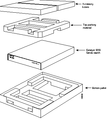
In the event you need to return or move the Catalyst 2900, the following instructions describe repacking the switch using the original packaging material:
Step 1 Set the Catalyst 2900 in the bottom pallet. (See Figure 2-8.)
Step 2 Place the top packing material over the top of the Catalyst 2900.
Step 3 Place both accessory boxes on the top packing material.
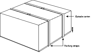
Step 4 Place the outside carton over the entire package.
Step 5 Fold the outside carton down over the top of the accessory boxes and seal with packing tape.
Step 6 Wrap two packaging straps tightly around the top and bottom of the package to hold the outside carton and the bottom pallet together. (See Figure 2-9.)
|
|