|
|

This chapter explains process you should follow to install the Catalyst 2600 Token Ring Switch.
The basic installation steps are:
Step 1 Unpacking the Catalyst 2600.
Step 2 Gathering Other Materials You Will Need.
Step 3 Installing a Universal Feature Card.
Step 4 Setting Up the Catalyst 2600.
Step 5 Cabling the Catalyst 2600.
Step 6 Powering On the Catalyst 2600.
To unpack the Catalyst 2600, follow these steps:
Step 1 Open the carton.
Step 2 Remove the power cord and bag containing the MIB diskette, cable management bracket, and other assorted items.
Step 3 Remove the Catalyst 2600 from its protective packaging.
Step 4 Visually inspect the Catalyst 2600 to ensure that it was not damaged during shipment. Along with this manual, the package should contain:
If any item is missing or damaged, contact your Cisco Systems representative.
To install the Catalyst 2600, you need the following items:
Follow these steps to install a Universal Feature Card (UFC).
Step 1 Power off the Catalyst 2600.
Step 2 Remove the UFC from its box.
Step 3 Remove the Universal Feature Card slot faceplate by unscrewing the thumb screws. Retain the plate and thumbscrews for use in the event you ever remove a UFC.
Step 4 Slide the UFC into the slot, being careful to align the sides of the UFC with the guide rails. Continue sliding the UFC into the slot until it is seated into the connector at the back of the slot.
Step 5 Secure the card with the thumbscrews attached to it.
Use the Catalyst 2600 Cabling Chart in the "Cable and Pin Information" appendix to determine whether the switch will be mounted in a rack or as a standalone, such as on a tabletop.
Follow these steps to mount the Catalyst 2600 in a rack:
Step 1 Look at the rack inventory chart provided by your network administrator to determine where in the rack the Catalyst 2600 should be mounted.
Step 2 Obtain two screws that fit the mounting holes in the rack and put them and the cable management bracket within reach of the front of the rack.
Step 3 Place the Catalyst 2600 in the rack, lining up the holes on the rack with those on the mounting brackets. Only two holes are needed for mounting. The Catalyst 2600 takes up 2 units in a standard EIA rack. When the top of the Catalyst 2600 is even with an EIA unit boundary, the bracket holes align with holes in the rack.
Step 4 While supporting the Catalyst 2600, secure only the left side of the unit with one screw.
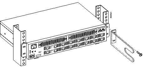
Step 5 Align the hole in the cable management bracket with the hole on the right-hand mounting bracket and the rack. Secure the cable management bracket and the right side of the unit to the rack, as shown in Figure 3-1, with one screw.

Step 6 Secure the Catalyst 2600 using the remaining two screws.
Step 7 Continue with the instructions under "Cabling the Catalyst 2600."
Follow these steps to mount the Catalyst 2600 as a standalone unit:
Step 1 Loosen the four screws that attach the two mounting brackets to the sides of the chassis.
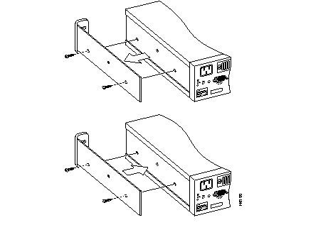
Step 2 Rotate the brackets and reattach them to the Catalyst 2600 as shown in Figure 3-2.

Step 3 Place the Catalyst 2600 on the surface where it is to be used.
Step 4 Continue with the instructions in "Cabling the Catalyst 2600."
This section provides instructions for connecting devices (such as hubs, servers, personal computers, and workstations) to a Catalyst 2600. Remember these tips when connecting cables:
Use this procedure if you will not use in-the-wall cables to connect devices to Token Ring ports on the Catalyst 2600.
If you will use in-the-wall cables (building wiring), go to "Connecting Devices to the Token Ring Ports Using Building Wiring."
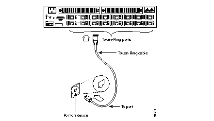
Step 1 Using the Catalyst 2600 Cabling Chart provided by your network administrator as a guide, connect the cables between the Catalyst 2600 and other devices.
The example in Figure 3-3 depicts an RJ-45 connector on each end. Depending on the cable type you use, the device end of the cable may also have a 9-pin D-shell or 150-ohm Data Connector.

Step 2 If the Catalyst 2600 is rack-mounted, run the Catalyst 2600 end of the cables to the right, through the cable management bracket.
Step 3 Label each end of the cables so that it will be easy to find the device if you have to troubleshoot a network problem.
The label should indicate: the room location of the device at the other end, a unique cable identification number, the MAC address of the connected device, and the number of the port to which the cable is attached.
Step 4 Continue with the instructions in "Powering On the Catalyst 2600."
Use this procedure if you will use in-the-wall cables to connect devices to the Catalyst 2600.
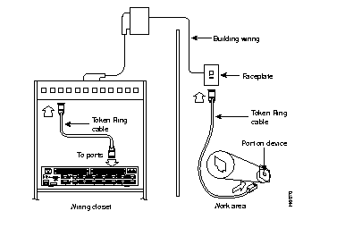
Step 1 Using the Catalyst 2600 Cabling Chart provided by your administrator as a guide, connect the cables between the devices and the faceplates, as illustrated in Figure 3-4.

Step 2 Label the faceplate, so that it will be easier to find the device if you have to troubleshoot a network problem.
Step 3 In the wiring closet, connect a cable to the Token Ring connector on the patch panel or other equipment where the building wiring terminates.
Step 4 Connect the other end of the cable to a Token Ring port on the Catalyst 2600.
Step 5 Label this cable.
Step 6 If the Catalyst 2600 is rack-mounted, run the Catalyst 2600 end of the cables to the right, through the cable management bracket.
Step 7 Continue with the instructions in "Powering On the Catalyst 2600."
To power on the Catalyst 2600 and to verify that it is operating correctly, perform the following steps:
Step 1 Connect the power cord to the Catalyst 2600 and then to an electrical outlet. The Catalyst 2600 is powered on when you plug in the power cord. There is no power switch.
Step 2 Verify that the Power LED on the left side of the front panel is on. If it is not, make sure that the outlet is working correctly. If the outlet is working but the Power LED is off, contact your Cisco Systems representative.
Step 3 Verify that diagnostics have been completed successfully.
The Catalyst 2600 automatically performs a self-test when connected to a power supply. During the test, the OK and Fault LEDs should behave as follows:
Note that the Tx/Rx LEDs next to each port blink during self-test even when a device is not attached to the port.
If the self-test is successful (the OK LED is on and the Fault LED is off), physical installation of the Catalyst 2600 is complete.To customize the configuration of the Catalyst 2600, refer to
If the LEDs are not in the normal state, refer to "Hardware Troubleshooting".
|
|