|
|

This chapter is a detailed procedure for installing Catalyst 2100 on a table, shelf or rack, and connecting it to other devices. The first thing to do is to ensure that you have all the components. When unpacking the unit, turn to the section "Packing List" in the "Fast Install Guide" for the list of included items.
The nature of rack-mounted equipment requires that the following guidelines be observed:
To install the unit in the rack:
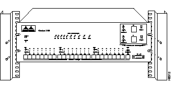
Step 1 Position the unit on the rack by lining up the integrated mounting ears with the holes in the rack, as shown in Figure 4-1.

Step 2 Attach the Catalyst 2100 unit to the rack with the four provided screws.
Step 3 Connect the power cord to Catalyst 2100 and to the power outlet.
Step 4 Turn the unit on using the power switch on the rear panel.
The power LED will come on and Catalyst 2100 will automatically start a self-test. This test is described in the section "Power-On Self-Test (POST)" in this chapter.
Use these instructions to install Catalyst 2100 on a table or shelf.
Step 1 Attach the four rubber feet included in the Catalyst 2100 cushioning kit to the bottom of the unit.
Step 2 Place the Catalyst 2100 unit on the table or shelf near a power source.
Step 3 Connect the power cord to Catalyst 2100 and to the power outlet.
Step 4 Turn Catalyst 2100 on using the power switch on the rear panel.
The power LED will come on and Catalyst 2100 will automatically start the series of tests described in the section "Power-On Self-Test (POST)."
When Catalyst 2100 is first turned on it lights all LEDs and executes a Power-On Self-Test (POST). There are 15 tests run in reverse order starting with number 15. As a test is running, the column of port LEDs with that test number are turned off. When the test passes, the LEDs are turned back on and the next test performed. A complete description of the 15 POST tests in included in the section "POST Failure" in the "Troubleshooting" chapter.
Tests 9 and 10 each take about 30 seconds; the other tests last a few seconds each. If a test fails, the associated LED column remains off during the remainder of the tests. When all the tests have completed, the LEDs for each passed test remain on, and the LEDs for each failed test remain off. When all tests pass, all LEDs are turned off.
For more details about the POST, see the section "POST Failure" in the "Troubleshooting" chapter.
Catalyst 2100 is configured with the default settings shown in Table 4-1.
| Catalyst 2100 Feature | Default Setting | Management Console Menu and Page |
|---|---|---|
| Switching mode | FastForward | "System Configuration" in the "Out-of-Band Management" chapter |
| Spanning-Tree Protocol | Enabled | "Spanning-Tree Configuration" in the "Out-of-Band Management" chapter |
| Addressing security | Disabled | "Port Addressing" in the "Out-of-Band Management" chapter |
| VLAN configuration | All ports belong to VLAN1 | "VLAN Configuration" in the "Out-of-Band Management" chapter |
| Port monitoring | Disabled | "Monitoring Configuration" in the "Out-of-Band Management" chapter |
| Flooding unknown unicast packets | Enabled | "Port Addressing" in the "Out-of-Band Management" chapter |
| Flooding unregistered multicast packets | Enabled | "Port Addressing" in the "Out-of-Band Management" chapter |
| Full duplex | Disabled | "Port Configuration" in the "Out-of-Band Management" chapter |
| Assign IP address to Catalyst 2100 | 0.0.0.0 | "IP Configuration" in the "Out-of-Band Management" chapter |
| Define trap manager | 0.0.0.0 | "Network Management (SNMP) Configuration" in the "Out-of-Band Management" chapter |
| Action on address violation | Suspend | "System Configuration" in the "Out-of-Band Management" chapter |
If you find some of these terms unfamiliar, they are described in detail in the "Concepts" chapter. See the section "Configuration Menus" in the "Out-of-Band Management" chapter for instructions on changing the default settings. If you're using SNMP you can set these parameters according to the list of supported MIB objects found in the section "Standard MIBs and MIB Extensions" in the "In-Band Management" chapter.
Once Catalyst 2100 is installed you can begin connecting devices to its ports. Note that all UTP connections, whether 10Base-T or 100Base-TX, must be within 100 meters of Catalyst 2100.
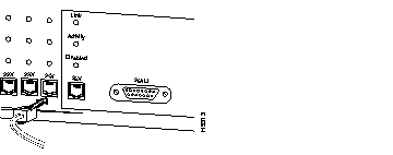
Step 1 Insert the cable into one RJ-45 connector as shown in Figure 4-2.

Step 2 Insert the other end of the cable into the RJ-45 connector of the target device. The link LED will light when both Catalyst 2100 and the connected device are turned on. If the link LED does not light, the device at the other end may not be turned on, there may be a cable problem or a problem with the adapter installed in the attached device. See the "Troubleshooting" chapter for more information.
Step 3 Reboot the connected device as needed.
Repeat steps 1 through 3 for each device that needs to be connected.
Use this procedure to connect the 100Base-TX ports to servers, hubs, routers or other Catalyst 2100s.
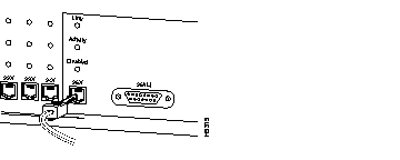
Step 1 Insert the cable into the RJ-45 connector as shown in Figure 4-3.
Step 2 Insert the other end of the cable into the RJ-45 connector of the target device. The link LED will light when both Catalyst 2100 and the connected device are turned on. If the link LED does not light, the device at the other end may not be turned on, there may be a cable problem or a problem with the adapter in the attached device. See the section "Diagnosing Problems" in the "Troubleshooting" chapter for more information.
Step 3 Reboot the connected device as needed.
Step 4 Repeat steps 1 through 4 for each device to be connected.

Port 25 is described separately because it can be connected via an RJ-45 or AUI connector. Only one connector for the port can be used at a time. Catalyst 2100 can self-sense the connector being used and no configuration is necessary. You can also define which connector is to be used through the Catalyst 2100 management console or an SNMP MIB object.

If you are using the RJ-45 connector, use the procedure in the section "Connecting to 10BaseT Ports 1 Through 5" in this chapter to connect to another device.
Use the AUI connector on the front panel to connect to an external transceiver for attachment to a thick coaxial, thin coaxial, or fiber-optic cable.
Step 1 Install the appropriate external transceiver on the network. Refer to the transceiver manual for installation instructions.
Step 2 Insert the AUI cable into the AUI connector on Catalyst 2100, as shown in Figure 4-5.
Step 3 Slide the latch into the closed position.
Step 4 Attach the other end of the cable to the transceiver.

Use the RS-232 cable shipped with Catalyst 2100 to connect a terminal to the RS-232 port on the Catalyst 2100's back panel.

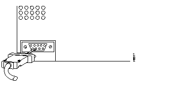
Step 1 Using the cable supplied with the Catalyst 2100, insert the connector into the receptacle as shown in Figure 4-6.
Step 2 Insert the other end of the cable into the terminal.
Step 3 Boot the terminal emulation program on your terminal.
Step 4 The Catalyst 2100 logon panel appears.
Catalyst 2100 is configured to expect the following parameters:
|
|