|
|

This appendix describes the physical characteristics and connector pinouts of the
Catalyst 2100.
This section describes the following connectors used by Catalyst 2100:
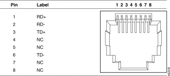
Ports 1 through 25 use standard RJ-45 connectors and 10Base-T pin-outs with internal cross-over, as indicated by an X. These 10Base-T ports have their transmit (TD) and receive (RD) signals internally crossed, for attachment of an adapter using a straight-through cable.

The pinout for the 100Base-TX ports is shown in Table A-3.

The AUI connector is a 15-pin female receptacle shown in Figure A-1; the pinouts are shown in Table A-4.

1 | GND | Ground |
| 2 | CI+ | Positive AUI differential collision-data input |
| 3 | TX+ | Positive AUI differential transmit-data input |
| 4 | GND | Ground |
| 5 | RX+ | Positive AUI differential receive-data output |
| 6 | GND | Ground |
| 7 | NC | |
| 8 | GND | Ground |
| 9 | CI- | Negative AUI differential collision data |
| 10 | TX- | Negative AUI differential transmit-data input |
| 11 | GND | Ground |
| 12 | RX- | Negative AUI differential receive data output |
| 13 | +12V | 12 Volt supply for external MAU |
| 14 | GND | Ground |
| 15 | NC |
The serial connector is a male 9-pin D subminiature connector as shown in Figure A-2.

The pinouts are shown in Table A-5.
1 | DCD |
| 2 | RD |
| 3 | TD |
| 4 | DTR |
| 5 | GND |
| 6 | DSR |
| 7 | RTS |
| 8 | CTS |
| 9 | RI |
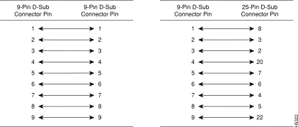
The shell is connected to the chassis ground. Use a standard modem cable to connect to a modem. Use a null-modem cable to connect to a terminal.
Either piece of equipment may come with either 25-pin or 9-pin connectors.


|
|